Manual
Page 1
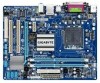
GA-G41MT-ES2L LGA775 socket motherboard for Intel® Core™ processor family/ Intel® Pentium® processor family/Intel® Celeron® processor family User's Manual Rev. 1101 12ME-G41MT2L-1101R
GA-G41MT-ES2L LGA775 socket motherboard for Intel® Core™ processor family/ Intel® Pentium® processor family/Intel® Celeron® processor family User's Manual Rev. 1101 12ME-G41MT2L-1101R
Manual
Page 2
Motherboard GA-G41MT-ES2L Oct. 23, 2009 Motherboard GA-G41MT-ES2L Oct. 23, 2009
Motherboard GA-G41MT-ES2L Oct. 23, 2009 Motherboard GA-G41MT-ES2L Oct. 23, 2009
Manual
Page 3
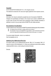
For example, "REV: 1.0" means the revision of the motherboard is the property of GIGABYTE. Check your motherboard looks like this: "REV: X.X." Disclaimer Information in the use GIGABYTE's unique features, read the User's Manual. For instructions on how to the ...their respective owners. The trademarks mentioned in any form or by GIGABYTE without GIGABYTE's prior written permission. For product-related information, check on our website at: http://www.gigabyte.com.tw Identifying Your Motherboard Revision The revision number on our website. All rights reserved. ...
For example, "REV: 1.0" means the revision of the motherboard is the property of GIGABYTE. Check your motherboard looks like this: "REV: X.X." Disclaimer Information in the use GIGABYTE's unique features, read the User's Manual. For instructions on how to the ...their respective owners. The trademarks mentioned in any form or by GIGABYTE without GIGABYTE's prior written permission. For product-related information, check on our website at: http://www.gigabyte.com.tw Identifying Your Motherboard Revision The revision number on our website. All rights reserved. ...
Manual
Page 4
Table of Contents Box Contents...6 Optional Items...6 GA-G41MT-ES2L Motherboard Layout 7 Block Diagram...8 Chapter 1 Hardware Installation 9 1-1 Installation Precautions 9 1-2 Product Specifications 10 1-3 Installing the CPU and CPU Cooler 13 1-3-1 Installing the CPU 13 1-3-2 Installing the CPU ...
Table of Contents Box Contents...6 Optional Items...6 GA-G41MT-ES2L Motherboard Layout 7 Block Diagram...8 Chapter 1 Hardware Installation 9 1-1 Installation Precautions 9 1-2 Product Specifications 10 1-3 Installing the CPU and CPU Cooler 13 1-3-1 Installing the CPU 13 1-3-2 Installing the CPU ...
Manual
Page 6
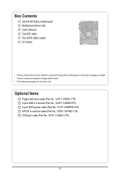
... SATA power cable (Part No. 12CF1-2SERPW-0*R) S/PDIF In and Out cable (Part No. 12CR1-1SPINO-1*R) COM port cable (Part No. 12CF1-1CM001-3*R) - 6 - Box Contents GA-G41MT-ES2L motherboard Motherboard driver disk User's Manual One IDE cable Two SATA 3Gb/s cables I/O Shield • The box contents above are subject to change without notice. • The...
... SATA power cable (Part No. 12CF1-2SERPW-0*R) S/PDIF In and Out cable (Part No. 12CR1-1SPINO-1*R) COM port cable (Part No. 12CF1-1CM001-3*R) - 6 - Box Contents GA-G41MT-ES2L motherboard Motherboard driver disk User's Manual One IDE cable Two SATA 3Gb/s cables I/O Shield • The box contents above are subject to change without notice. • The...
Manual
Page 7
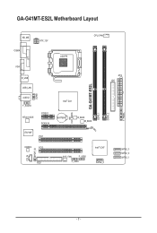
GA-G41MT-ES2L Motherboard Layout CLR_CMOS GA-G41MT-ES2L DDR3_1 DDR3_2 F_PANEL KB_MS COMA ATX_12V LGA775 CPU_FAN LPT COMB VGA R_USB USB_LAN AUDIO F_AUDIO RTL8111D/E PCIEX1 PCIEX16 IT8718F PCI1 Intel® G41 BATTERY B_BIOS M_BIOS ATX IDE CODEC PCI2 CD_IN SPDIF_IO FDD SYS_FAN F_USB2 F_USB1 Intel® ICH7 SATA2_0 SATA2_3 SATA2_2 SATA2_1 - 7 -
GA-G41MT-ES2L Motherboard Layout CLR_CMOS GA-G41MT-ES2L DDR3_1 DDR3_2 F_PANEL KB_MS COMA ATX_12V LGA775 CPU_FAN LPT COMB VGA R_USB USB_LAN AUDIO F_AUDIO RTL8111D/E PCIEX1 PCIEX16 IT8718F PCI1 Intel® G41 BATTERY B_BIOS M_BIOS ATX IDE CODEC PCI2 CD_IN SPDIF_IO FDD SYS_FAN F_USB2 F_USB1 Intel® ICH7 SATA2_0 SATA2_3 SATA2_2 SATA2_1 - 7 -
Manual
Page 9
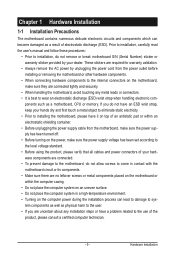
... the AC power by your hands dry and first touch a metal object to eliminate static electricity. • Prior to installing the motherboard, please have it on top of an antistatic pad or within an electrostatic shielding container. • Before unplugging the power supply cable... from the power outlet before installing or removing the motherboard or other hardware components. • When connecting hardware components to the internal connectors on the computer power during the installation process...
... the AC power by your hands dry and first touch a metal object to eliminate static electricity. • Prior to installing the motherboard, please have it on top of an antistatic pad or within an electrostatic shielding container. • Before unplugging the power supply cable... from the power outlet before installing or removing the motherboard or other hardware components. • When connecting hardware components to the internal connectors on the computer power during the installation process...
Manual
Page 12
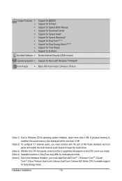
... 3) Whether the CPU fan speed control function is supported will depend on the CPU cooler you install. (Note 4) Available functions in EasyTune may differ by motherboard model. (Note 5) Due to the hardware limitation, you must install the Intel®CoreTM 2 Extreme/ CoreTM 2 Quad/ CoreTM 2 Duo/ Pentium Dual-Core/ Celeron Dual-Core...
... 3) Whether the CPU fan speed control function is supported will depend on the CPU cooler you install. (Note 4) Available functions in EasyTune may differ by motherboard model. (Note 5) Due to the hardware limitation, you must install the Intel®CoreTM 2 Extreme/ CoreTM 2 Quad/ CoreTM 2 Duo/ Pentium Dual-Core/ Celeron Dual-Core...
Manual
Page 13
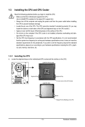
... host frequency in accordance with the CPU specifications. Locate the alignment keys on the motherboard CPU socket and the notches on the computer if the CPU cooler is not recommended that the motherboard supports the CPU. (Go to GIGABYTE's website for the peripherals. 1-3 Installing the CPU and CPU Cooler Read the following guidelines...
... host frequency in accordance with the CPU specifications. Locate the alignment keys on the motherboard CPU socket and the notches on the computer if the CPU cooler is not recommended that the motherboard supports the CPU. (Go to GIGABYTE's website for the peripherals. 1-3 Installing the CPU and CPU Cooler Read the following guidelines...
Manual
Page 14
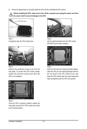
... the load plate and push the CPU socket lever back into position. Before installing the CPU, make sure to correctly install the CPU into the motherboard CPU socket.
... the load plate and push the CPU socket lever back into position. Before installing the CPU, make sure to correctly install the CPU into the motherboard CPU socket.
Manual
Page 15
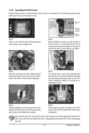
... 3: Place the cooler atop the CPU, aligning the four push pins through the pin holes on the motherboard. Hardware Installation Direction of the Arrow Sign on the Male Push Pin Male Push Pin The Top of ...the cooler.) Step 5: After the installation, check the back of the motherboard. Check that the Male and Female push pins are joined closely. (Refer to correctly install the CPU cooler on ...the motherboard. (The following procedure uses Intel® boxed cooler as the picture above shows, the installation ...
... 3: Place the cooler atop the CPU, aligning the four push pins through the pin holes on the motherboard. Hardware Installation Direction of the Arrow Sign on the Male Push Pin Male Push Pin The Top of ...the cooler.) Step 5: After the installation, check the back of the motherboard. Check that the Male and Female push pins are joined closely. (Refer to correctly install the CPU cooler on ...the motherboard. (The following procedure uses Intel® boxed cooler as the picture above shows, the installation ...
Manual
Page 16
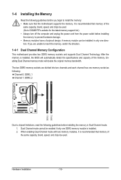
... to install the memory: • Make sure that memory of the same capacity, brand, speed, and chips be used . (Go to GIGABYTE's website for the latest memory support list.) • Always turn off the computer and unplug the power cord from the power outlet before installing...Dual Channel mode. 1. The two DDR3 memory sockets are unable to insert the memory, switch the direction. 1-4-1 Dual Channel Memory Configuration This motherboard provides two DDR3 memory sockets and supports Dual Channel Technology. When enabling Dual Channel mode with two memory modules, it is recommended that memory ...
... to install the memory: • Make sure that memory of the same capacity, brand, speed, and chips be used . (Go to GIGABYTE's website for the latest memory support list.) • Always turn off the computer and unplug the power cord from the power outlet before installing...Dual Channel mode. 1. The two DDR3 memory sockets are unable to insert the memory, switch the direction. 1-4-1 Dual Channel Memory Configuration This motherboard provides two DDR3 memory sockets and supports Dual Channel Technology. When enabling Dual Channel mode with two memory modules, it is recommended that memory ...
Manual
Page 17
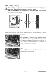
... on the memory and insert it can only fit in the memory sockets. Hardware Installation Follow the steps below to install DDR3 DIMMs on this motherboard. Step 2: The clips at both ends of the memory, push down on the socket. 1-4-2 Installing a Memory Before installing a memory module, make sure to turn off...
... on the memory and insert it can only fit in the memory sockets. Hardware Installation Follow the steps below to install DDR3 DIMMs on this motherboard. Step 2: The clips at both ends of the memory, push down on the socket. 1-4-2 Installing a Memory Before installing a memory module, make sure to turn off...
Manual
Page 18
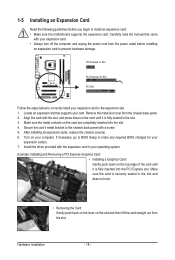
... following guidelines before installing an expansion card to prevent hardware damage. Secure the card's metal bracket to install an expansion card: • Make sure the motherboard supports the expansion card. Make sure the card is fully inserted into the slot. 4. Remove the metal slot cover from the slot. Align the card...
... following guidelines before installing an expansion card to prevent hardware damage. Secure the card's metal bracket to install an expansion card: • Make sure the motherboard supports the expansion card. Make sure the card is fully inserted into the slot. 4. Remove the metal slot cover from the slot. Align the card...
Manual
Page 19
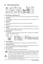
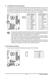
... up a 2/4/5.1/7.1-channel audio configuration in jack. Mic In Jack (Pink) The default Mic in a 4/5.1-channel audio configuration. Do not rock it straight out from the motherboard. • When removing the cable, pull it side to side to connect front speakers in jack. Use this audio jack for USB devices such as...
... up a 2/4/5.1/7.1-channel audio configuration in jack. Mic In Jack (Pink) The default Mic in a 4/5.1-channel audio configuration. Do not rock it straight out from the motherboard. • When removing the cable, pull it side to side to connect front speakers in jack. Use this audio jack for USB devices such as...
Manual
Page 20
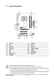
..., make sure your devices are compliant with the connectors you wish to connect. • Before installing the devices, be sure to the connector on the motherboard.
..., make sure your devices are compliant with the connectors you wish to connect. • Before installing the devices, be sure to the connector on the motherboard.
Manual
Page 21
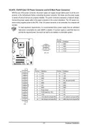
... installed. Hardware Installation Connect the power supply cable to the CPU. To meet expansion requirements, it is turned off and all the components on the motherboard. If the 12V power connector is used (500W or greater). If a power supply is not connected, the computer will not start. The 12V power connector...
... installed. Hardware Installation Connect the power supply cable to the CPU. To meet expansion requirements, it is turned off and all the components on the motherboard. If the 12V power connector is used (500W or greater). If a power supply is not connected, the computer will not start. The 12V power connector...
Manual
Page 22
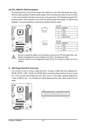
Most fan headers possess a foolproof insertion design. The motherboard supports CPU fan speed control, which requires the use of different color. The types of the connector and the floppy disk drive cable. Definition 1 GND 2 +.... 1 2 3 Definition GND +12V Sense • Be sure to connect fan cables to the fan headers to connect a floppy disk drive. 3/4) CPU_FAN/SYS_FAN (Fan Headers) The motherboard has a 4-pin CPU fan header (CPU_FAN) and a 3-pin (SYS_FAN) system fan header. Do not place a jumper cap on the headers. 5) FDD (Floppy Disk Drive Connector...
Most fan headers possess a foolproof insertion design. The motherboard supports CPU fan speed control, which requires the use of different color. The types of the connector and the floppy disk drive cable. Definition 1 GND 2 +.... 1 2 3 Definition GND +12V Sense • Be sure to connect fan cables to the fan headers to connect a floppy disk drive. 3/4) CPU_FAN/SYS_FAN (Fan Headers) The motherboard has a 4-pin CPU fan header (CPU_FAN) and a 3-pin (SYS_FAN) system fan header. Do not place a jumper cap on the headers. 5) FDD (Floppy Disk Drive Connector...
Manual
Page 25
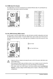
... assignments of the module connector match the pin assignments of a single plug. Incorrect connection between the module connector and the motherboard header will be present on each wire instead of the motherboard header. Definition 1 CD-L 2 GND 3 GND 4 CD-R - 25 - 9) F_AUDIO (Front Panel Audio Header) The front panel audio header supports Intel High...
... assignments of the module connector match the pin assignments of a single plug. Incorrect connection between the module connector and the motherboard header will be present on each wire instead of the motherboard header. Definition 1 CD-L 2 GND 3 GND 4 CD-R - 25 - 9) F_AUDIO (Front Panel Audio Header) The front panel audio header supports Intel High...
Manual
Page 27
... Pin 14) CLR_CMOS (Clearing CMOS Jumper) Use this jumper to Chapter 2, "BIOS Setup," for a few seconds. Failure to do so may cause damage to the motherboard. • After system restart, go to BIOS Setup to load factory defaults (select Load Optimized Defaults) or manually configure the BIOS settings (refer to clear...
... Pin 14) CLR_CMOS (Clearing CMOS Jumper) Use this jumper to Chapter 2, "BIOS Setup," for a few seconds. Failure to do so may cause damage to the motherboard. • After system restart, go to BIOS Setup to load factory defaults (select Load Optimized Defaults) or manually configure the BIOS settings (refer to clear...


