Manual
Page 3
... For product-related information, check on our website at: http://www.gigabyte.com.tw Identifying Your Motherboard Revision The revision number on your motherboard revision before updating motherboard BIOS, drivers, or when looking for technical information. The trademarks mentioned in... and is 1.0. Check your motherboard looks like this manual may be made by GIGABYTE without GIGABYTE's prior written permission. Disclaimer Information in this product, GIGABYTE provides the following types of GIGABYTE. Example: For example, "REV: 1.0" means the revision of this manual may...
... For product-related information, check on our website at: http://www.gigabyte.com.tw Identifying Your Motherboard Revision The revision number on your motherboard revision before updating motherboard BIOS, drivers, or when looking for technical information. The trademarks mentioned in... and is 1.0. Check your motherboard looks like this manual may be made by GIGABYTE without GIGABYTE's prior written permission. Disclaimer Information in this product, GIGABYTE provides the following types of GIGABYTE. Example: For example, "REV: 1.0" means the revision of this manual may...
Manual
Page 4
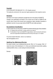
Table of Contents Box Contents...6 Optional Items...6 GA-G41MT-ES2L Motherboard Layout 7 Block Diagram...8 Chapter 1 Hardware Installation 9 1-1 Installation Precautions 9 1-2 Product Specifications 10 1-3 Installing the CPU and CPU Cooler... Installing an Expansion Card 18 1-6 Back Panel Connectors 19 1-7 Internal Connectors 20 Chapter 2 BIOS Setup 29 2-1 Startup Screen 30 2-2 The Main Menu 31 2-3 MB Intelligent Tweaker(M.I.T 33 2-4 Standard CMOS Features 39 2-5 Advanced BIOS Features 41 2-6 Advanced Chipset Features 43 2-7 Integrated Peripherals 45 2-8 Power Management Setup 48 ...
Table of Contents Box Contents...6 Optional Items...6 GA-G41MT-ES2L Motherboard Layout 7 Block Diagram...8 Chapter 1 Hardware Installation 9 1-1 Installation Precautions 9 1-2 Product Specifications 10 1-3 Installing the CPU and CPU Cooler... Installing an Expansion Card 18 1-6 Back Panel Connectors 19 1-7 Internal Connectors 20 Chapter 2 BIOS Setup 29 2-1 Startup Screen 30 2-2 The Main Menu 31 2-3 MB Intelligent Tweaker(M.I.T 33 2-4 Standard CMOS Features 39 2-5 Advanced BIOS Features 41 2-6 Advanced Chipset Features 43 2-7 Integrated Peripherals 45 2-8 Power Management Setup 48 ...
Manual
Page 5
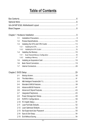
... 56 3-3 Technical Manuals 56 3-4 Contact...57 3-5 System...57 3-6 Download Center 58 Chapter 4 Unique Features 59 4-1 Xpress Recovery2 59 4-2 BIOS Update Utilities 62 4-2-1 Updating the BIOS with the Q-Flash Utility 62 4-2-2 Updating the BIOS with the @BIOS Utility 65 4-3 EasyTune 6...66 4-4 Easy Energy Saver 67 4-5 Q-Share...69 4-6 Time Repair...70 Chapter 5 Appendix...71 5-1 Configuring Audio...
... 56 3-3 Technical Manuals 56 3-4 Contact...57 3-5 System...57 3-6 Download Center 58 Chapter 4 Unique Features 59 4-1 Xpress Recovery2 59 4-2 BIOS Update Utilities 62 4-2-1 Updating the BIOS with the Q-Flash Utility 62 4-2-2 Updating the BIOS with the @BIOS Utility 65 4-3 EasyTune 6...66 4-4 Easy Energy Saver 67 4-5 Q-Share...69 4-6 Time Repair...70 Chapter 5 Appendix...71 5-1 Configuring Audio...
Manual
Page 8
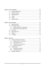
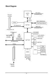
Block Diagram PCIe CLK (100 MHz) D-Sub PCI Express x16 1 PCI Express x16 1 PCI Express x1 PCIe CLK (100 MHz) LAN RJ45 RTL8111D/E PCI Express Bus PCI Bus LGA775 CPU CPU CLK+/(333/266/200 MHz) Host Interface Intel® G41 DDR3 1066/800 MHz Dual Channel Memory GMCH CLK (333/266/200 MHz) Intel® ICH7 CODEC Dual BIOS ATA-100/66/33 IDE Channel 4 SATA 3Gb/s 8 USB Ports IT8718 Floppy LPT Port COM Ports PS/2 KB/Mouse MIC Line Out Line In S/PDIF In S/PDIF Out 2 PCI PCI CLK (33 MHz) - 8 -
Block Diagram PCIe CLK (100 MHz) D-Sub PCI Express x16 1 PCI Express x16 1 PCI Express x1 PCIe CLK (100 MHz) LAN RJ45 RTL8111D/E PCI Express Bus PCI Bus LGA775 CPU CPU CLK+/(333/266/200 MHz) Host Interface Intel® G41 DDR3 1066/800 MHz Dual Channel Memory GMCH CLK (333/266/200 MHz) Intel® ICH7 CODEC Dual BIOS ATA-100/66/33 IDE Channel 4 SATA 3Gb/s 8 USB Ports IT8718 Floppy LPT Port COM Ports PS/2 KB/Mouse MIC Line Out Line In S/PDIF In S/PDIF Out 2 PCI PCI CLK (33 MHz) - 8 -
Manual
Page 11
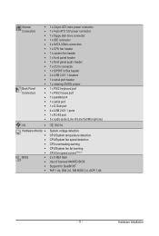
... w 1 x PS/2 mouse port w 1 x parallel port w 1 x serial port w 1 x D-Sub port w 4 x USB 2.0/1.1 ports w 1 x RJ-45 port w 3 x audio jacks (Line In/Line Out/Microphone) I/O w iTE IT8718 Hardware Monitor w w w w w w BIOS w w w w System voltage detection CPU/System temperature detection CPU/System fan speed detection CPU overheating warning CPU/System fan fail warning CPU fan speed control (Note...
... w 1 x PS/2 mouse port w 1 x parallel port w 1 x serial port w 1 x D-Sub port w 4 x USB 2.0/1.1 ports w 1 x RJ-45 port w 3 x audio jacks (Line In/Line Out/Microphone) I/O w iTE IT8718 Hardware Monitor w w w w w w BIOS w w w w System voltage detection CPU/System temperature detection CPU/System fan speed detection CPU overheating warning CPU/System fan fail warning CPU fan speed control (Note...
Manual
Page 12
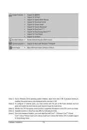
Hardware Installation - 12 - Unique Features w w w w w w w w w w Bundled Software w Support for @BIOS Support for Q-Flash Support for Xpress BIOS Rescue Support for Download Center Support for Xpress Install Support for Xpress Recovery2 Support for EasyTune (Note 4) Support for Easy Energy Saver (Note 5) Support for ...
Hardware Installation - 12 - Unique Features w w w w w w w w w w Bundled Software w Support for @BIOS Support for Q-Flash Support for Xpress BIOS Rescue Support for Download Center Support for Xpress Install Support for Xpress Recovery2 Support for EasyTune (Note 4) Support for Easy Energy Saver (Note 5) Support for ...
Manual
Page 16
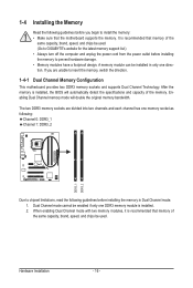
... will automatically detect the specifications and capacity of the memory. When enabling Dual Channel mode with two memory modules, it is installed, the BIOS will double the original memory bandwidth. After the memory is recommended that memory of the same capacity, brand, speed, and chips be installed...unable to install the memory: • Make sure that memory of the same capacity, brand, speed, and chips be used . (Go to GIGABYTE's website for the latest memory support list.) • Always turn off the computer and unplug the power cord from the power outlet before installing the...
... will automatically detect the specifications and capacity of the memory. When enabling Dual Channel mode with two memory modules, it is installed, the BIOS will double the original memory bandwidth. After the memory is recommended that memory of the same capacity, brand, speed, and chips be installed...unable to install the memory: • Make sure that memory of the same capacity, brand, speed, and chips be used . (Go to GIGABYTE's website for the latest memory support list.) • Always turn off the computer and unplug the power cord from the power outlet before installing the...
Manual
Page 18
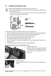
... the slot. 3. Turn on the top edge of the card until it is securely seated in the expansion slot. 1. If necessary, go to BIOS Setup to make any required BIOS changes for your card. Example: Installing and Removing a PCI Express Graphics Card: • Installing a Graphics Card: Gently push down on the slot...
... the slot. 3. Turn on the top edge of the card until it is securely seated in the expansion slot. 1. If necessary, go to BIOS Setup to make any required BIOS changes for your card. Example: Installing and Removing a PCI Express Graphics Card: • Installing a Graphics Card: Gently push down on the slot...

Manual
Page 24
...Switch): Connects to the power switch on the chassis front panel. One single short beep will be heard if no problem is detected, the BIOS may issue beeps in different patterns to the speaker on the chassis front panel. When connecting your system using the power switch (refer to ...Chapter 2, "BIOS Setup," "Power Management Setup," for information about beep codes. • HD (Hard Drive Activity LED) Connects to the power status indicator on the...
...Switch): Connects to the power switch on the chassis front panel. One single short beep will be heard if no problem is detected, the BIOS may issue beeps in different patterns to the speaker on the chassis front panel. When connecting your system using the power switch (refer to ...Chapter 2, "BIOS Setup," "Power Management Setup," for information about beep codes. • HD (Hard Drive Activity LED) Connects to the power status indicator on the...
Manual
Page 27
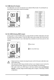
... to temporarily short the two pins or use a metal object like a screwdriver to touch the two pins for BIOS configurations). - 27 - Hardware Installation date information and BIOS configurations) and reset the CMOS values to remove the jumper cap from the jumper. For purchasing the optional COM port... 1 2 9 10 Pin No. 1 2 3 4 5 6 7 8 9 10 Definition NDCDNSIN NSOUT NDTRGND NDSRNRTSNCTSNRINo Pin 14) CLR_CMOS (Clearing CMOS Jumper) Use this jumper to Chapter 2, "BIOS Setup," for a few seconds. Failure to do so may cause damage to the motherboard. • After system restart, go to...
... to temporarily short the two pins or use a metal object like a screwdriver to touch the two pins for BIOS configurations). - 27 - Hardware Installation date information and BIOS configurations) and reset the CMOS values to remove the jumper cap from the jumper. For purchasing the optional COM port... 1 2 9 10 Pin No. 1 2 3 4 5 6 7 8 9 10 Definition NDCDNSIN NSOUT NDTRGND NDSRNRTSNCTSNRINo Pin 14) CLR_CMOS (Clearing CMOS Jumper) Use this jumper to Chapter 2, "BIOS Setup," for a few seconds. Failure to do so may cause damage to the motherboard. • After system restart, go to...

Manual
Page 28
15) BATTERY The battery provides power to keep the values (such as BIOS configurations, date, and time information) in the power cord and restart your computer. • Always turn off your computer and unplug the power cord. 2. Gently ...
15) BATTERY The battery provides power to keep the values (such as BIOS configurations, date, and time information) in the power cord and restart your computer. • Always turn off your computer and unplug the power cord. 2. Gently ...
Manual
Page 29
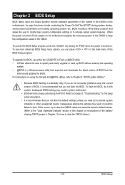
...it is recommended that you need to) to boot. Chapter 2 BIOS Setup BIOS (Basic Input and Output System) records hardware parameters of the system in the CMOS on . To upgrade the BIOS, use either the GIGABYTE Q-Flash or @BIOS utility. • Q-Flash allows the user to activate certain system... features. Inadequately altering the settings may result in the CMOS. BIOS Setup To access the BIOS Setup program, press the key during the...
...it is recommended that you need to) to boot. Chapter 2 BIOS Setup BIOS (Basic Input and Output System) records hardware parameters of the system in the CMOS on . To upgrade the BIOS, use either the GIGABYTE Q-Flash or @BIOS utility. • Q-Flash allows the user to activate certain system... features. Inadequately altering the settings may result in the CMOS. BIOS Setup To access the BIOS Setup program, press the key during the...
Manual
Page 30
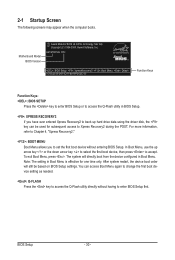
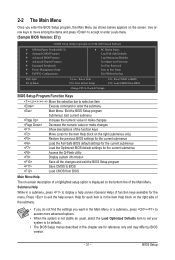
G41MT-ES2L E7c . . . . : BIOS Setup : XpressRecovery2 : Boot Menu : Qflash 10/06/2009-G41-ICH7-6A79PG03C-00 Function Keys Function Keys: : BIOS SETUP Press the key to enter BIOS Setup or to access the Q-Flash utility in BIOS Setup. : XPRESS RECOVERY2 If you to set the first boot device without ... the device configured in Boot Menu is effective for subsequent access to enter BIOS Setup first. BIOS Setup - 30 - The system will still be used for one time only. Motherboard Model BIOS Version Award Modular BIOS v6.00PG, An Energy Star Ally Copyright (C) 1984-2009, Award Software...
G41MT-ES2L E7c . . . . : BIOS Setup : XpressRecovery2 : Boot Menu : Qflash 10/06/2009-G41-ICH7-6A79PG03C-00 Function Keys Function Keys: : BIOS SETUP Press the key to enter BIOS Setup or to access the Q-Flash utility in BIOS Setup. : XPRESS RECOVERY2 If you to set the first boot device without ... the device configured in Boot Menu is effective for subsequent access to enter BIOS Setup first. BIOS Setup - 30 - The system will still be used for one time only. Motherboard Model BIOS Version Award Modular BIOS v6.00PG, An Energy Star Ally Copyright (C) 1984-2009, Award Software...
Manual
Page 31
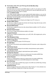
... Without Saving ESC: Quit F8: Q-Flash Select Item F10: Save & Exit Setup Change CPU's Clock & Voltage F11: Save CMOS to BIOS F12: Load CMOS from BIOS BIOS Setup Program Function Keys Move the selection bar to select an item Execute command or enter the submenu Main Menu: Exit the...numeric value or make changes Show descriptions of the function keys Move cursor to its defaults. • The BIOS Setup menus described in a submenu, press to BIOS Load CMOS from BIOS Main Menu Help The on-screen description of a highlighted setup option is not stable as shown below) ...
... Without Saving ESC: Quit F8: Q-Flash Select Item F10: Save & Exit Setup Change CPU's Clock & Voltage F11: Save CMOS to BIOS F12: Load CMOS from BIOS BIOS Setup Program Function Keys Move the selection bar to select an item Execute command or enter the submenu Main Menu: Exit the...numeric value or make changes Show descriptions of the function keys Move cursor to its defaults. • The BIOS Setup menus described in a submenu, press to BIOS Load CMOS from BIOS Main Menu Help The on-screen description of a highlighted setup option is not stable as shown below) ...
Manual
Page 32
... system operations. Set Supervisor Password Change, set , or disable password. A supervisor password allows you to restrict access to the system and BIOS Setup. First enter the profile name (to erase the default profile name, use this task.) Exit Without Saving Abandon all the changes made... and date, hard drive types, floppy disk drive types, and the type of errors that stop the system boot, etc. Advanced BIOS Features Use this menu to configure the device boot order, advanced features available on the CPU, and the primary display adapter. Advanced ...
... system operations. Set Supervisor Password Change, set , or disable password. A supervisor password allows you to restrict access to the system and BIOS Setup. First enter the profile name (to erase the default profile name, use this task.) Exit Without Saving Abandon all the changes made... and date, hard drive types, floppy disk drive types, and the type of errors that stop the system boot, etc. Advanced BIOS Features Use this menu to configure the device boot order, advanced features available on the CPU, and the primary display adapter. Advanced ...
Manual
Page 33
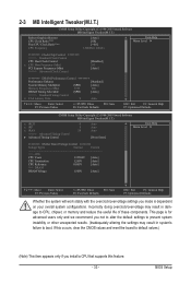
... or other unexpected results. (Inadequately altering the settings may result in damage to CPU, chipset, or memory and reduce the useful life of these components. BIOS Setup
... or other unexpected results. (Inadequately altering the settings may result in damage to CPU, chipset, or memory and reduce the useful life of these components. BIOS Setup

Manual
Page 34
Auto allows the BIOS to automatically set this item to 333 MHz. Options are dependent on system configurations. For a 1066 MHz FSB CPU, set the R.G.B. PCI Express Frequency (Mhz) ..., set this feature. Robust Graphics Booster Robust Graphics Booster (R.G.B.) helps to enhance the performance of CPU host clock. Enabled will allow for the installed CPU. BIOS Setup - 34 - System Memory Multiplier (SPD) Allows you to 200 MHz.
Auto allows the BIOS to automatically set this item to 333 MHz. Options are dependent on system configurations. For a 1066 MHz FSB CPU, set the R.G.B. PCI Express Frequency (Mhz) ..., set this feature. Robust Graphics Booster Robust Graphics Booster (R.G.B.) helps to enhance the performance of CPU host clock. Enabled will allow for the installed CPU. BIOS Setup - 34 - System Memory Multiplier (SPD) Allows you to 200 MHz.

Manual
Page 35
... [Press Enter] [Press Enter] Move Enter: Select F5: Previous Values +/-/PU/PD: Value F10: Save F6: Fail-Safe Defaults tRRD Options are : Auto (default), 1~15. BIOS Setup the second is the memory frequency that is the normal operating frequency of the memory being used; tRP Options are : Auto (default), 1~15.
... [Press Enter] [Press Enter] Move Enter: Select F5: Previous Values +/-/PU/PD: Value F10: Save F6: Fail-Safe Defaults tRRD Options are : Auto (default), 1~15. BIOS Setup the second is the memory frequency that is the normal operating frequency of the memory being used; tRP Options are : Auto (default), 1~15.
Manual
Page 36
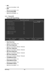
.... Trd2rd(Different Rank) Options are : Auto (default), 0-Normal, 1-Advanced. Twr2rd(Different Rank) Options are : Auto (default), 1~15. ESC: Exit F1: General Help F7: Optimized Defaults BIOS Setup - 36 - tRTP Options are : Auto (default), 1~15. tRD Phase3 Adjustment Options are : Auto (default), 1~15. Command Rate(CMD) Options are: Auto (default), 1~3. >>>>> Channel A/B Channel...
.... Trd2rd(Different Rank) Options are : Auto (default), 0-Normal, 1-Advanced. Twr2rd(Different Rank) Options are : Auto (default), 1~15. ESC: Exit F1: General Help F7: Optimized Defaults BIOS Setup - 36 - tRTP Options are : Auto (default), 1~15. tRD Phase3 Adjustment Options are : Auto (default), 1~15. Command Rate(CMD) Options are: Auto (default), 1~3. >>>>> Channel A/B Channel...
Manual
Page 37
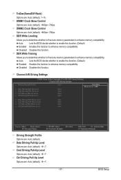
...Write Leveling Allows you to determine whether to fine-tune memory parameters to enable this function. (Default) Enabled Enables this function. Auto Lets the BIOS decide whether to enhance memory compatibility. ESC: Exit F1: General Help F7: Optimized Defaults - 37 - Data Driving Pull-Up Level Options are... +/-/PU/PD: Value F10: Save F6: Fail-Safe Defaults Driving Strength Profile Options are : Auto (default), +800ps~-700ps. BIOS Setup Auto Lets the BIOS decide whether to enhance memory compatibility. Trd2wr(Same/Diff Rank) Options are: Auto (default), 1~15.
...Write Leveling Allows you to determine whether to fine-tune memory parameters to enable this function. (Default) Enabled Enables this function. Auto Lets the BIOS decide whether to enhance memory compatibility. ESC: Exit F1: General Help F7: Optimized Defaults - 37 - Data Driving Pull-Up Level Options are... +/-/PU/PD: Value F10: Save F6: Fail-Safe Defaults Driving Strength Profile Options are : Auto (default), +800ps~-700ps. BIOS Setup Auto Lets the BIOS decide whether to enhance memory compatibility. Trd2wr(Same/Diff Rank) Options are: Auto (default), 1~15.


