Manual
Page 3
... to use GIGABYTE's unique features, read or download the information on/from the Support&Downloads\Motherboard\Technology Guide page on your motherboard revision before updating motherboard BIOS, drivers, or when looking for technical information. For example, "REV: 1.0" means the revision of the motherboard is the property of this manual is protected by GIGABYTE without GIGABYTE's prior written permission. Copyright © 2010 GIGA-BYTE TECHNOLOGY CO., LTD. No part of GIGABYTE. For...
... to use GIGABYTE's unique features, read or download the information on/from the Support&Downloads\Motherboard\Technology Guide page on your motherboard revision before updating motherboard BIOS, drivers, or when looking for technical information. For example, "REV: 1.0" means the revision of the motherboard is the property of this manual is protected by GIGABYTE without GIGABYTE's prior written permission. Copyright © 2010 GIGA-BYTE TECHNOLOGY CO., LTD. No part of GIGABYTE. For...
Manual
Page 4
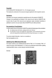
Table of Contents Box Contents...6 Optional Items...6 GA-G41MT-ES2L Motherboard Layout 7 Block Diagram...8 Chapter 1 Hardware Installation 9 1-1 Installation Precautions 9 1-2 Product Specifications 10 1-3 Installing the CPU and CPU Cooler 13 1-3-1 Installing the CPU 13 1-3-2 Installing the CPU Cooler 15 1-4 Installing the Memory 16 1-4-1 Dual Channel Memory Configuration 16 1-4-2 Installing a Memory 17 1-5 Installing an Expansion Card 18 1-6 Back Panel Connectors 19 1-7 Internal Connectors 20 Chapter 2 BIOS Setup 29 2-1 Startup Screen 30 2-2 The Main Menu 31 2-3 MB Intelligent...
Table of Contents Box Contents...6 Optional Items...6 GA-G41MT-ES2L Motherboard Layout 7 Block Diagram...8 Chapter 1 Hardware Installation 9 1-1 Installation Precautions 9 1-2 Product Specifications 10 1-3 Installing the CPU and CPU Cooler 13 1-3-1 Installing the CPU 13 1-3-2 Installing the CPU Cooler 15 1-4 Installing the Memory 16 1-4-1 Dual Channel Memory Configuration 16 1-4-2 Installing a Memory 17 1-5 Installing an Expansion Card 18 1-6 Back Panel Connectors 19 1-7 Internal Connectors 20 Chapter 2 BIOS Setup 29 2-1 Startup Screen 30 2-2 The Main Menu 31 2-3 MB Intelligent...
Manual
Page 6
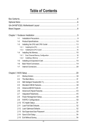
Optional Items Floppy disk drive cable (Part No. 12CF1-1FD001-7*R) 2-port USB 2.0 bracket (Part No. 12CR1-1UB030-5*R) 2-port SATA power cable (Part No. 12CF1-2SERPW-0*R) S/PDIF In and Out cable (Part No. 12CR1-1SPINO-1*R) COM port cable (Part No. 12CF1-1CM001-3*R) - 6 - The box contents are for reference only. Box Contents GA-G41MT-ES2L motherboard Motherboard driver disk User's Manual One IDE cable Two SATA 3Gb/s cables I/O Shield • The box contents above are subject to change without notice. • The motherboard image is for reference...
Optional Items Floppy disk drive cable (Part No. 12CF1-1FD001-7*R) 2-port USB 2.0 bracket (Part No. 12CR1-1UB030-5*R) 2-port SATA power cable (Part No. 12CF1-2SERPW-0*R) S/PDIF In and Out cable (Part No. 12CR1-1SPINO-1*R) COM port cable (Part No. 12CF1-1CM001-3*R) - 6 - The box contents are for reference only. Box Contents GA-G41MT-ES2L motherboard Motherboard driver disk User's Manual One IDE cable Two SATA 3Gb/s cables I/O Shield • The box contents above are subject to change without notice. • The motherboard image is for reference...
Manual
Page 12
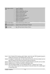
... 4 GB of physical memory is installed, the actual memory size displayed will be less than 4 GB. (Note 2) To configure 7.1-channel audio, you need connect with the port of HD Audio standard via front panel and enable the multi-channel audio feature through the audio driver. (Note 3) Whether the CPU fan speed control function is supported will depend on the CPU cooler you install. (Note 4) Available functions in EasyTune may differ by motherboard model. (Note 5) Due to...
... 4 GB of physical memory is installed, the actual memory size displayed will be less than 4 GB. (Note 2) To configure 7.1-channel audio, you need connect with the port of HD Audio standard via front panel and enable the multi-channel audio feature through the audio driver. (Note 3) Whether the CPU fan speed control function is supported will depend on the CPU cooler you install. (Note 4) Available functions in EasyTune may differ by motherboard model. (Note 5) Due to...
Manual
Page 16
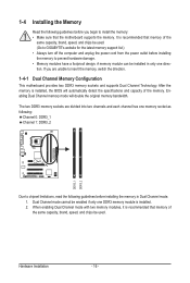
..., speed, and chips be used . (Go to GIGABYTE's website for the latest memory support list.) • Always turn off the computer and unplug the power cord from the power outlet before installing the memory to insert the memory, switch the direction. 1-4-1 Dual Channel Memory Configuration This motherboard provides two DDR3 memory sockets and supports Dual Channel Technology. The two DDR3 memory sockets are unable to prevent hardware damage. • Memory modules have a foolproof design. When enabling Dual Channel mode with two memory modules...
..., speed, and chips be used . (Go to GIGABYTE's website for the latest memory support list.) • Always turn off the computer and unplug the power cord from the power outlet before installing the memory to insert the memory, switch the direction. 1-4-1 Dual Channel Memory Configuration This motherboard provides two DDR3 memory sockets and supports Dual Channel Technology. The two DDR3 memory sockets are unable to prevent hardware damage. • Memory modules have a foolproof design. When enabling Dual Channel mode with two memory modules...
Manual
Page 18
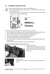
... the expansion slot. 1. Align the card with a screw. 5. After installing all expansion cards, replace the chassis cover(s). 6. If necessary, go to BIOS Setup to make any required BIOS changes for your expansion card. • Always turn off the computer and unplug the power cord from the power outlet before you begin to install an expansion card: • Make sure the motherboard supports the expansion card. 1-5 Installing an Expansion Card Read the...
... the expansion slot. 1. Align the card with a screw. 5. After installing all expansion cards, replace the chassis cover(s). 6. If necessary, go to BIOS Setup to make any required BIOS changes for your expansion card. • Always turn off the computer and unplug the power cord from the power outlet before you begin to install an expansion card: • Make sure the motherboard supports the expansion card. 1-5 Installing an Expansion Card Read the...
Manual
Page 27
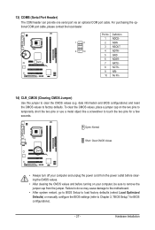
... Chapter 2, "BIOS Setup," for a few seconds. Hardware Installation Open: Normal Short: Clear CMOS Values • Always turn off your computer, be sure to factory defaults. For purchasing the optional COM port cable, please contact the local dealer. 1 2 9 10 Pin No. 1 2 3 4 5 6 7 8 9 10 Definition NDCDNSIN NSOUT NDTRGND NDSRNRTSNCTSNRINo Pin 14) CLR_CMOS (Clearing CMOS Jumper) Use this jumper to clear the CMOS values (e.g. 13) COMB (Serial Port Header) The COM header can provide one serial port via an optional COM port cable.
... Chapter 2, "BIOS Setup," for a few seconds. Hardware Installation Open: Normal Short: Clear CMOS Values • Always turn off your computer, be sure to factory defaults. For purchasing the optional COM port cable, please contact the local dealer. 1 2 9 10 Pin No. 1 2 3 4 5 6 7 8 9 10 Definition NDCDNSIN NSOUT NDTRGND NDSRNRTSNCTSNRINo Pin 14) CLR_CMOS (Clearing CMOS Jumper) Use this jumper to clear the CMOS values (e.g. 13) COMB (Serial Port Header) The COM header can provide one serial port via an optional COM port cable.
Manual
Page 29
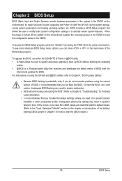
... entering the operating system. • @BIOS is a Windows-based utility that searches and downloads the latest version of BIOS, it with caution. To upgrade the BIOS, use either the GIGABYTE Q-Flash or @BIOS utility. • Q-Flash allows the user to boot. Refer to Chapter 5, "Troubleshooting," for how to keep the configuration values in the CMOS on . To access the BIOS Setup program, press the key during the POST when the power is turned off, the battery on the motherboard supplies...
... entering the operating system. • @BIOS is a Windows-based utility that searches and downloads the latest version of BIOS, it with caution. To upgrade the BIOS, use either the GIGABYTE Q-Flash or @BIOS utility. • Q-Flash allows the user to boot. Refer to Chapter 5, "Troubleshooting," for how to keep the configuration values in the CMOS on . To access the BIOS Setup program, press the key during the POST when the power is turned off, the battery on the motherboard supplies...
Manual
Page 32
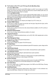
..., hard drive types, floppy disk drive types, and the type of errors that stop the system boot, etc. Advanced BIOS Features Use this menu to configure the device boot order, advanced features available on the CPU, and the primary display adapter. Advanced Chipset Features Use this menu to configure advanced features available on the chipset. Integrated Peripherals Use this menu to configure all peripheral devices, such as IDE, SATA, USB, integrated audio, and integrated LAN, etc. Power Management Setup Use this menu...
..., hard drive types, floppy disk drive types, and the type of errors that stop the system boot, etc. Advanced BIOS Features Use this menu to configure the device boot order, advanced features available on the CPU, and the primary display adapter. Advanced Chipset Features Use this menu to configure advanced features available on the chipset. Integrated Peripherals Use this menu to configure all peripheral devices, such as IDE, SATA, USB, integrated audio, and integrated LAN, etc. Power Management Setup Use this menu...
Manual
Page 33
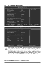
..., clear the CMOS values and reset the board to CPU, chipset, or memory and reduce the useful life of these components. 2-3 MB Intelligent Tweaker(M.I.T.) CMOS Setup Utility-Copyright (C) 1984-2009 Award Software MB Intelligent Tweaker(M.I.T.) Robust Graphics Booster CPU Clock Ratio (Note) Fine CPU Clock Ratio (Note) CPU Frequency [Auto] [8X] [+0.0] 1.60GHz ( 200x8) Item Help Menu Level ******** Clock Chip Control Standard Clock Control CPU Host Clock Control x CPU Host Frequency (Mhz) PCI Express Frequency (Mhz) >>>>> Advanced Clock Control [Disabled] 333 [Auto...
..., clear the CMOS values and reset the board to CPU, chipset, or memory and reduce the useful life of these components. 2-3 MB Intelligent Tweaker(M.I.T.) CMOS Setup Utility-Copyright (C) 1984-2009 Award Software MB Intelligent Tweaker(M.I.T.) Robust Graphics Booster CPU Clock Ratio (Note) Fine CPU Clock Ratio (Note) CPU Frequency [Auto] [8X] [+0.0] 1.60GHz ( 200x8) Item Help Menu Level ******** Clock Chip Control Standard Clock Control CPU Host Clock Control x CPU Host Frequency (Mhz) PCI Express Frequency (Mhz) >>>>> Advanced Clock Control [Disabled] 333 [Auto...

Manual
Page 34
...: It is highly recommended that supports this item to 1200 MHz. BIOS Setup - 34 - CPU Frequency Displays the current operating CPU frequency. ******** Clock Chip Control Standard Clock Control CPU Host Clock Control Enables or disables the control of the graphics chip and memory. Enabled will allow for automated system reboot, or clear the CMOS values to reset the board to default values. (Default: Disabled) CPU Host Frequency (Mhz) Allows you to be set this feature. Note: If your system fails to boot after overclocking, please wait...
...: It is highly recommended that supports this item to 1200 MHz. BIOS Setup - 34 - CPU Frequency Displays the current operating CPU frequency. ******** Clock Chip Control Standard Clock Control CPU Host Clock Control Enables or disables the control of the graphics chip and memory. Enabled will allow for automated system reboot, or clear the CMOS values to reset the board to default values. (Default: Disabled) CPU Host Frequency (Mhz) Allows you to be set this feature. Note: If your system fails to boot after overclocking, please wait...
Manual
Page 41
... supports this feature. Capability Enables or disables the S.M.A.R.T. (Self Monitoring and Reporting Technology) capability of your system to report read/write errors of the hard drive and to accept. Options are: Floppy, LS120, Hard Disk, CDROM, ZIP, USB-FDD, USB-ZIP, USB-CDROM, USB-HDD, Legacy LAN, Disabled. The settings here synchronize with the settings of the SMART QuickBoot of loading the operating system from the available devices. Press to deliver greater efficiency for entering the BIOS Setup...
... supports this feature. Capability Enables or disables the S.M.A.R.T. (Self Monitoring and Reporting Technology) capability of your system to report read/write errors of the hard drive and to accept. Options are: Floppy, LS120, Hard Disk, CDROM, ZIP, USB-FDD, USB-ZIP, USB-CDROM, USB-HDD, Legacy LAN, Disabled. The settings here synchronize with the settings of the SMART QuickBoot of loading the operating system from the available devices. Press to deliver greater efficiency for entering the BIOS Setup...

Manual
Page 43
... a PCI Express card is not seen by the operating system and not available to playback HDCP contents. If you wish to set up a dual view configuration, set this function if you wish to any user application. Init Display First Specifies the first initiation of system memory during boot. Blu-ray disc). 2-6 Advanced Chipset Features CMOS Setup Utility-Copyright (C) 1984-2009 Award Software Advanced Chipset Features ** VGA Setting ** Onboard VGA Init Display First PAVP Mode...
... a PCI Express card is not seen by the operating system and not available to playback HDCP contents. If you wish to set up a dual view configuration, set this function if you wish to any user application. Init Display First Specifies the first initiation of system memory during boot. Blu-ray disc). 2-6 Advanced Chipset Features CMOS Setup Utility-Copyright (C) 1984-2009 Award Software Advanced Chipset Features ** VGA Setting ** Onboard VGA Init Display First PAVP Mode...
Manual
Page 45
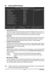
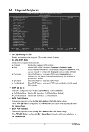
...all SATA devices to Combined or Enhanced mode. PATA IDE Set to This item is configurable only if the On-Chip SATA Mode is automatically configured to Combined mode, you can manually re-configure it to Enhanced mode as needed. (Default) Combined Sets all SATA devices to Azalia Codec Onboard H/W LAN Green LAN } SMART LAN Onboard LAN Boot ROM Onboard Serial Port 1 Onboard Serial Port 2 Onboard Parallel Port Parallel Port Mode USB 1.0 Controller USB 2.0 Controller USB Keyboard Support USB Mouse Support USB Storage Function [Enabled...
...all SATA devices to Combined or Enhanced mode. PATA IDE Set to This item is configurable only if the On-Chip SATA Mode is automatically configured to Combined mode, you can manually re-configure it to Enhanced mode as needed. (Default) Combined Sets all SATA devices to Azalia Codec Onboard H/W LAN Green LAN } SMART LAN Onboard LAN Boot ROM Onboard Serial Port 1 Onboard Serial Port 2 Onboard Parallel Port Parallel Port Mode USB 1.0 Controller USB 2.0 Controller USB Keyboard Support USB Mouse Support USB Storage Function [Enabled...
Manual
Page 46
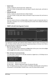
.... (Default: Disabled) SMART LAN (LAN Cable Diagnostic Function) CMOS Setup Utility-Copyright (C) 1984-2009 Award Software SMART LAN Start detecting at a normal speed of 10/100/1000 Mbps in Windows mode or when the LAN Boot ROM is connected or not. If not, the corresponding LAN controller will only operate at Port..... Onboard H/W LAN Enables or disables the onboard LAN function. (Default: Enabled) If you wish to install a 3rd party add-in audio card instead of using the onboard LAN, set this item to Disabled. it will dynamically detect if a LAN cable...
.... (Default: Disabled) SMART LAN (LAN Cable Diagnostic Function) CMOS Setup Utility-Copyright (C) 1984-2009 Award Software SMART LAN Start detecting at a normal speed of 10/100/1000 Mbps in Windows mode or when the LAN Boot ROM is connected or not. If not, the corresponding LAN controller will only operate at Port..... Onboard H/W LAN Enables or disables the onboard LAN function. (Default: Enabled) If you wish to install a 3rd party add-in audio card instead of using the onboard LAN, set this item to Disabled. it will dynamically detect if a LAN cable...
Manual
Page 47
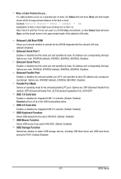
... the onboard parallel (LPT) port. Onboard LAN Boot ROM Allows you to decide whether to activate the boot ROM integrated with the onboard LAN chip. (Default: Disabled) Onboard Serial Port 1 Enables or disables the first serial port and specifies its base I /O address and corresponding interrupt. Options are : Auto, 3F8/IRQ4 (default), 2F8/IRQ3, 3E8/IRQ4, 2E8/IRQ3, Disabled. BIOS Setup USB 1.0 Controller Enables or disables the integrated USB 1.0 controller. (Default: Enabled) Disabled will be used in a 10/100 Mbps environment, so their Status fields will show Short...
... the onboard parallel (LPT) port. Onboard LAN Boot ROM Allows you to decide whether to activate the boot ROM integrated with the onboard LAN chip. (Default: Disabled) Onboard Serial Port 1 Enables or disables the first serial port and specifies its base I /O address and corresponding interrupt. Options are : Auto, 3F8/IRQ4 (default), 2F8/IRQ3, 3E8/IRQ4, 2E8/IRQ3, Disabled. BIOS Setup USB 1.0 Controller Enables or disables the integrated USB 1.0 controller. (Default: Enabled) Disabled will be used in a 10/100 Mbps environment, so their Status fields will show Short...
Manual
Page 55
... installed, follow the on-screen instructions to install other applications included in the motherboard driver disk. • For USB 2.0 driver support under the Windows XP operating system, please install the Windows XP Service Pack 1 or later. Failure to do so may affect the driver installation. • Some device drivers will then autodetect and install the USB 2.0 driver.) - 55 - After installing the SP1 (or later), if a question mark still exists in Universal Serial Bus Controller in the screen...
... installed, follow the on-screen instructions to install other applications included in the motherboard driver disk. • For USB 2.0 driver support under the Windows XP operating system, please install the Windows XP Service Pack 1 or later. Failure to do so may affect the driver installation. • Some device drivers will then autodetect and install the USB 2.0 driver.) - 55 - After installing the SP1 (or later), if a question mark still exists in Universal Serial Bus Controller in the screen...
Manual
Page 62
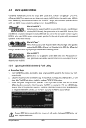
... the Q-Flash Utility A. Inadequate BIOS flashing may result in the BIOS, the Q-Flash tool frees you to update the BIOS without having to an independent IDE/SATA controller, use FAT32/16/12 file system. 3. What is Q-Flash™? For the sake of your floppy disk, USB flash drive, or hard drive. Note: The USB flash drive or hard drive must use the key during the POST or pressing the key in RAID/AHCI mode or a hard drive attached to enter operating systems like MS-DOS or Window first...
... the Q-Flash Utility A. Inadequate BIOS flashing may result in the BIOS, the Q-Flash tool frees you to update the BIOS without having to an independent IDE/SATA controller, use FAT32/16/12 file system. 3. What is Q-Flash™? For the sake of your floppy disk, USB flash drive, or hard drive. Note: The USB flash drive or hard drive must use the key during the POST or pressing the key in RAID/AHCI mode or a hard drive attached to enter operating systems like MS-DOS or Window first...
Manual
Page 63
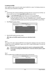
... floppy disk, USB flash drive, or hard drive when the system is complete, press any key to return to Drive Enter : Run hi:Move ESC:Reset F10:Power Off Total size : 0 Free size : 0 3. Q-Flash Utility v2.13 Flash Type/Size MXIC 25L8005 1M Keep0 DfilMe(Is)DfaotuandEnable Floppy A Loa d CMO S Default Enable HDD 1-0 Upda te BIOS from the floppy disk is displayed on the screen. When the message "Are you to save the BIOS file to update BIOS?" Update BIOS from Drive and press . • The Save Main BIOS...
... floppy disk, USB flash drive, or hard drive when the system is complete, press any key to return to Drive Enter : Run hi:Move ESC:Reset F10:Power Off Total size : 0 Free size : 0 3. Q-Flash Utility v2.13 Flash Type/Size MXIC 25L8005 1M Keep0 DfilMe(Is)DfaotuandEnable Floppy A Loa d CMO S Default Enable HDD 1-0 Upda te BIOS from the floppy disk is displayed on the screen. When the message "Are you to save the BIOS file to update BIOS?" Update BIOS from Drive and press . • The Save Main BIOS...
Manual
Page 79
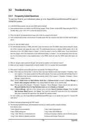
... Service Pack 1 or Service Pack 2 has been installed (check in Chapter 1 to short the jumper to the maximum volume? Step 2: Check if Audio Device on High Definition Audio Bus or Unknown device is the light of standby power after the computer shuts down ? A: The following Award BIOS beep code descriptions may help you identify possible computer problems. (For reference only.) 1 short: System boots successfully 1 long, 3 short: Keyboard error 2 short: CMOS setting error 1 long, 9 short: BIOS ROM error 1 long, 1 short: Memory or motherboard error Continuous long beeps: Graphics card...
... Service Pack 1 or Service Pack 2 has been installed (check in Chapter 1 to short the jumper to the maximum volume? Step 2: Check if Audio Device on High Definition Audio Bus or Unknown device is the light of standby power after the computer shuts down ? A: The following Award BIOS beep code descriptions may help you identify possible computer problems. (For reference only.) 1 short: System boots successfully 1 long, 3 short: Keyboard error 2 short: CMOS setting error 1 long, 9 short: BIOS ROM error 1 long, 1 short: Memory or motherboard error Continuous long beeps: Graphics card...


