Manual
Page 1
GA-G41MT-ES2L LGA775 socket motherboard for Intel® Core™ processor family/ Intel® Pentium® processor family/Intel® Celeron® processor family User's Manual Rev. 1101 12ME-G41MT2L-1101R
GA-G41MT-ES2L LGA775 socket motherboard for Intel® Core™ processor family/ Intel® Pentium® processor family/Intel® Celeron® processor family User's Manual Rev. 1101 12ME-G41MT2L-1101R
Manual
Page 2
Motherboard GA-G41MT-ES2L Oct. 23, 2009 Motherboard GA-G41MT-ES2L Oct. 23, 2009
Motherboard GA-G41MT-ES2L Oct. 23, 2009 Motherboard GA-G41MT-ES2L Oct. 23, 2009
Manual
Page 3
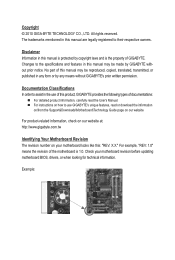
....tw Identifying Your Motherboard Revision The revision number on our website. Example: Disclaimer Information in the use of this product, GIGABYTE provides the following types of documentations: For detailed product information, carefully read the User's Manual. For ...to assist in this manual is protected by any form or by copyright laws and is 1.0. No part of GIGABYTE. Documentation Classifications In order to use GIGABYTE's unique features, read or download the information on/from the Support&Downloads\Motherboard\Technology Guide page on your motherboard...
....tw Identifying Your Motherboard Revision The revision number on our website. Example: Disclaimer Information in the use of this product, GIGABYTE provides the following types of documentations: For detailed product information, carefully read the User's Manual. For ...to assist in this manual is protected by any form or by copyright laws and is 1.0. No part of GIGABYTE. Documentation Classifications In order to use GIGABYTE's unique features, read or download the information on/from the Support&Downloads\Motherboard\Technology Guide page on your motherboard...
Manual
Page 4
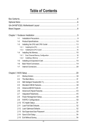
Table of Contents Box Contents...6 Optional Items...6 GA-G41MT-ES2L Motherboard Layout 7 Block Diagram...8 Chapter 1 Hardware Installation 9 1-1 Installation Precautions 9 1-2 Product Specifications 10 1-3 Installing the CPU and CPU Cooler 13 1-3-1 Installing the CPU 13 1-3-2 Installing the ...
Table of Contents Box Contents...6 Optional Items...6 GA-G41MT-ES2L Motherboard Layout 7 Block Diagram...8 Chapter 1 Hardware Installation 9 1-1 Installation Precautions 9 1-2 Product Specifications 10 1-3 Installing the CPU and CPU Cooler 13 1-3-1 Installing the CPU 13 1-3-2 Installing the ...
Manual
Page 5
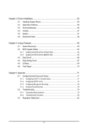
Chapter 3 Drivers Installation 55 3-1 Installing Chipset Drivers 55 3-2 Application Software 56 3-3 Technical Manuals 56 3-4 Contact...57 3-5 System...57 3-6 Download Center 58 Chapter 4 Unique Features 59 4-1 Xpress Recovery2 59 4-2 BIOS Update Utilities 62 4-2-1 Updating the BIOS with the Q-Flash Utility 62 4-2-2 Updating the BIOS with the @BIOS Utility 65 4-3 EasyTune 6...66 4-4 Easy Energy Saver 67 4-5 Q-Share...69 4-6 Time Repair...70 Chapter 5 Appendix...71 5-1 Configuring Audio Input and Output 71 5-1-1 Configuring 2/4/5.1/7.1-Channel Audio 71 5-1-2 Configuring S/PDIF In/...
Chapter 3 Drivers Installation 55 3-1 Installing Chipset Drivers 55 3-2 Application Software 56 3-3 Technical Manuals 56 3-4 Contact...57 3-5 System...57 3-6 Download Center 58 Chapter 4 Unique Features 59 4-1 Xpress Recovery2 59 4-2 BIOS Update Utilities 62 4-2-1 Updating the BIOS with the Q-Flash Utility 62 4-2-2 Updating the BIOS with the @BIOS Utility 65 4-3 EasyTune 6...66 4-4 Easy Energy Saver 67 4-5 Q-Share...69 4-6 Time Repair...70 Chapter 5 Appendix...71 5-1 Configuring Audio Input and Output 71 5-1-1 Configuring 2/4/5.1/7.1-Channel Audio 71 5-1-2 Configuring S/PDIF In/...
Manual
Page 6
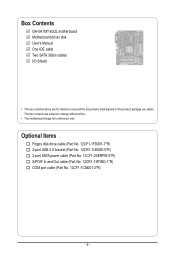
The box contents are for reference only. Box Contents GA-G41MT-ES2L motherboard Motherboard driver disk User's Manual One IDE cable Two SATA 3Gb/s cables I/O Shield • The box contents above are subject to change without notice. &#...
The box contents are for reference only. Box Contents GA-G41MT-ES2L motherboard Motherboard driver disk User's Manual One IDE cable Two SATA 3Gb/s cables I/O Shield • The box contents above are subject to change without notice. &#...
Manual
Page 7
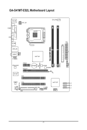
GA-G41MT-ES2L Motherboard Layout CLR_CMOS GA-G41MT-ES2L DDR3_1 DDR3_2 F_PANEL KB_MS COMA ATX_12V LGA775 CPU_FAN LPT COMB VGA R_USB USB_LAN AUDIO F_AUDIO RTL8111D/E PCIEX1 PCIEX16 IT8718F PCI1 Intel® G41 BATTERY B_BIOS M_BIOS ATX IDE CODEC PCI2 CD_IN SPDIF_IO FDD SYS_FAN F_USB2 F_USB1 Intel® ICH7 SATA2_0 SATA2_3 SATA2_2 SATA2_1 - 7 -
GA-G41MT-ES2L Motherboard Layout CLR_CMOS GA-G41MT-ES2L DDR3_1 DDR3_2 F_PANEL KB_MS COMA ATX_12V LGA775 CPU_FAN LPT COMB VGA R_USB USB_LAN AUDIO F_AUDIO RTL8111D/E PCIEX1 PCIEX16 IT8718F PCI1 Intel® G41 BATTERY B_BIOS M_BIOS ATX IDE CODEC PCI2 CD_IN SPDIF_IO FDD SYS_FAN F_USB2 F_USB1 Intel® ICH7 SATA2_0 SATA2_3 SATA2_2 SATA2_1 - 7 -
Manual
Page 8
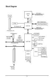
Block Diagram PCIe CLK (100 MHz) D-Sub PCI Express x16 1 PCI Express x16 1 PCI Express x1 PCIe CLK (100 MHz) LAN RJ45 RTL8111D/E PCI Express Bus PCI Bus LGA775 CPU CPU CLK+/(333/266/200 MHz) Host Interface Intel® G41 DDR3 1066/800 MHz Dual Channel Memory GMCH CLK (333/266/200 MHz) Intel® ICH7 CODEC Dual BIOS ATA-100/66/33 IDE Channel 4 SATA 3Gb/s 8 USB Ports IT8718 Floppy LPT Port COM Ports PS/2 KB/Mouse MIC Line Out Line In S/PDIF In S/PDIF Out 2 PCI PCI CLK (33 MHz) - 8 -
Block Diagram PCIe CLK (100 MHz) D-Sub PCI Express x16 1 PCI Express x16 1 PCI Express x1 PCIe CLK (100 MHz) LAN RJ45 RTL8111D/E PCI Express Bus PCI Bus LGA775 CPU CPU CLK+/(333/266/200 MHz) Host Interface Intel® G41 DDR3 1066/800 MHz Dual Channel Memory GMCH CLK (333/266/200 MHz) Intel® ICH7 CODEC Dual BIOS ATA-100/66/33 IDE Channel 4 SATA 3Gb/s 8 USB Ports IT8718 Floppy LPT Port COM Ports PS/2 KB/Mouse MIC Line Out Line In S/PDIF In S/PDIF Out 2 PCI PCI CLK (33 MHz) - 8 -
Manual
Page 9
ponents such as a motherboard, CPU or memory. These stickers are required for warranty validation. • Always remove the AC power by unplugging the power cord from the motherboard, make sure the power supply has been turned off. • Before turning on the power, make sure they are connected tightly and securely. • When handling the motherboard, avoid touching any installation steps or have it on top of an antistatic pad or within the computer casing. • Do not place the computer system on an uneven surface. • Do not place the computer system in a high-...
ponents such as a motherboard, CPU or memory. These stickers are required for warranty validation. • Always remove the AC power by unplugging the power cord from the motherboard, make sure the power supply has been turned off. • Before turning on the power, make sure they are connected tightly and securely. • When handling the motherboard, avoid touching any installation steps or have it on top of an antistatic pad or within the computer casing. • Do not place the computer system on an uneven surface. • Do not place the computer system in a high-...

Manual
Page 10
.../Intel® Core™ 2 Duo processor/ Intel® Pentium® processor/Intel® Celeron® processor in the LGA775 package (Go to GIGABYTE's website for the latest CPU support list.) L2 cache varies with CPU Front Side Bus w 1333/1066/800 MHz FSB Chipset w w Memory ...sockets supporting up to 4 GB of system memory (Note 1) Dual channel memory architecture Support for DDR3 1066/800 MHz memory modules (Go to GIGABYTE's website for the latest memory support list.) Integrated in the North Bridge: - 1 x D-Sub port Realtek ALC888B codec High Definition Audio 2/4/5.1/7.1-...
.../Intel® Core™ 2 Duo processor/ Intel® Pentium® processor/Intel® Celeron® processor in the LGA775 package (Go to GIGABYTE's website for the latest CPU support list.) L2 cache varies with CPU Front Side Bus w 1333/1066/800 MHz FSB Chipset w w Memory ...sockets supporting up to 4 GB of system memory (Note 1) Dual channel memory architecture Support for DDR3 1066/800 MHz memory modules (Go to GIGABYTE's website for the latest memory support list.) Integrated in the North Bridge: - 1 x D-Sub port Realtek ALC888B codec High Definition Audio 2/4/5.1/7.1-...
Manual
Page 11
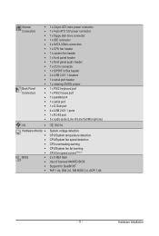
Internal Connectors Back Panel Connectors w 1 x 24-pin ATX main power connector w 1 x 4-pin ATX 12V power connector w 1 x floppy disk drive connector w 1 x IDE connector w 4 x SATA 3Gb/s connectors w 1 x CPU fan header w 1 x system fan header w 1 x front panel header w 1 x front panel audio header w 1 x CD In connector w 1 x S/PDIF In/Out header w 2 x USB 2.0/1.1 headers w 1 x serial port header w 1 x clearing CMOS jumper w 1 x PS/2 keyboard port w 1 x PS/2 mouse port w 1 x parallel port w 1 x serial port w 1 x D-Sub port w 4 x USB 2.0/1.1 ports w 1 x RJ-45 port w 3 x audio ...
Internal Connectors Back Panel Connectors w 1 x 24-pin ATX main power connector w 1 x 4-pin ATX 12V power connector w 1 x floppy disk drive connector w 1 x IDE connector w 4 x SATA 3Gb/s connectors w 1 x CPU fan header w 1 x system fan header w 1 x front panel header w 1 x front panel audio header w 1 x CD In connector w 1 x S/PDIF In/Out header w 2 x USB 2.0/1.1 headers w 1 x serial port header w 1 x clearing CMOS jumper w 1 x PS/2 keyboard port w 1 x PS/2 mouse port w 1 x parallel port w 1 x serial port w 1 x D-Sub port w 4 x USB 2.0/1.1 ports w 1 x RJ-45 port w 3 x audio ...
Manual
Page 12
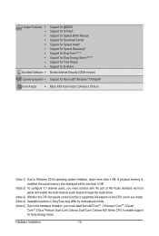
Hardware Installation - 12 - Unique Features w w w w w w w w w w Bundled Software w Support for @BIOS Support for Q-Flash Support for Xpress BIOS Rescue Support for Download Center Support for Xpress Install Support for Xpress Recovery2 Support for EasyTune (Note 4) Support for Easy Energy Saver (Note 5) Support for Time Repair Support for Q-Share Norton Internet Security (OEM version) Operating System w Support for Microsoft® Windows® 7/Vista/XP Form Factor w Micro ATX Form Factor; 24.4cm x 19.4cm (Note 1) Due to ...
Hardware Installation - 12 - Unique Features w w w w w w w w w w Bundled Software w Support for @BIOS Support for Q-Flash Support for Xpress BIOS Rescue Support for Download Center Support for Xpress Install Support for Xpress Recovery2 Support for EasyTune (Note 4) Support for Easy Energy Saver (Note 5) Support for Time Repair Support for Q-Share Norton Internet Security (OEM version) Operating System w Support for Microsoft® Windows® 7/Vista/XP Form Factor w Micro ATX Form Factor; 24.4cm x 19.4cm (Note 1) Due to ...
Manual
Page 13
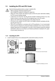
... of the CPU. • Do not turn on the computer if the CPU cooler is not recommended that the motherboard supports the CPU. (Go to GIGABYTE's website for the peripherals. If you may occur. • Set the CPU host frequency in accordance with the CPU specifications. Hardware Installation It is not...
... of the CPU. • Do not turn on the computer if the CPU cooler is not recommended that the motherboard supports the CPU. (Go to GIGABYTE's website for the peripherals. If you may occur. • Set the CPU host frequency in accordance with the CPU specifications. Hardware Installation It is not...
Manual
Page 14
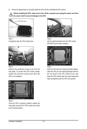
Follow the steps below to turn off the computer and unplug the power cord from the load plate. (To protect the CPU socket, always replace the protective socket cover when the CPU is properly inserted, replace the load plate and push the CPU socket lever back into its locked position. CPU Socket Lever Step 1: Completely raise the CPU socket lever. Step 5: Once the CPU is not installed.) Step 4: Hold the CPU with the socket alignment keys) and gently insert the CPU into the motherboard CPU socket. Step 2: Lift the metal load plate from the CPU socket. (DO NOT touch socket contacts.)...
Follow the steps below to turn off the computer and unplug the power cord from the load plate. (To protect the CPU socket, always replace the protective socket cover when the CPU is properly inserted, replace the load plate and push the CPU socket lever back into its locked position. CPU Socket Lever Step 1: Completely raise the CPU socket lever. Step 5: Once the CPU is not installed.) Step 4: Hold the CPU with the socket alignment keys) and gently insert the CPU into the motherboard CPU socket. Step 2: Lift the metal load plate from the CPU socket. (DO NOT touch socket contacts.)...
Manual
Page 15
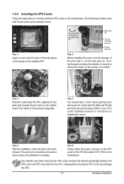
Direction of the Arrow Sign on the Male Push Pin Male Push Pin The Top of Female Push Pin Female Push Pin Step 2: Before installing the cooler, note the direction of the arrow sign on the male push pin. (Turning the push pin along the direction of arrow is to remove the cooler, on the contrary, is to install.) Step 3: Place the cooler atop the CPU, aligning the four push pins through the pin holes on the push pins diagonally. Push down each push pin. Check that the Male and Female push pins are joined closely. (Refer to your CPU cooler installation manual for instructions on the ...
Direction of the Arrow Sign on the Male Push Pin Male Push Pin The Top of Female Push Pin Female Push Pin Step 2: Before installing the cooler, note the direction of the arrow sign on the male push pin. (Turning the push pin along the direction of arrow is to remove the cooler, on the contrary, is to install.) Step 3: Place the cooler atop the CPU, aligning the four push pins through the pin holes on the push pins diagonally. Push down each push pin. Check that the Male and Female push pins are joined closely. (Refer to your CPU cooler installation manual for instructions on the ...
Manual
Page 16
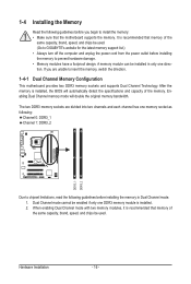
... Dual Channel mode with two memory modules, it is recommended that memory of the memory. Hardware Installation - 16 - A memory module can be used . (Go to GIGABYTE's website for the latest memory support list.) • Always turn off the computer and unplug the power cord from the power outlet before installing the...
... Dual Channel mode with two memory modules, it is recommended that memory of the memory. Hardware Installation - 16 - A memory module can be used . (Go to GIGABYTE's website for the latest memory support list.) • Always turn off the computer and unplug the power cord from the power outlet before installing the...
Manual
Page 17
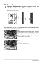
Step 2: The clips at both ends of the memory socket. Hardware Installation 1-4-2 Installing a Memory Before installing a memory module, make sure to turn off the computer and unplug the power cord from the power outlet to prevent damage to install DDR3 DIMMs on the memory and insert it can only fit in the memory sockets. Follow the steps below to correctly install your fingers on the top edge of the memory module. Spread the retaining clips at both ends of the socket will snap into the memory socket. As indicated in the picture on the left, place your memory modules in one...
Step 2: The clips at both ends of the memory socket. Hardware Installation 1-4-2 Installing a Memory Before installing a memory module, make sure to turn off the computer and unplug the power cord from the power outlet to prevent damage to install DDR3 DIMMs on the memory and insert it can only fit in the memory sockets. Follow the steps below to correctly install your fingers on the top edge of the memory module. Spread the retaining clips at both ends of the socket will snap into the memory socket. As indicated in the picture on the left, place your memory modules in one...
Manual
Page 18
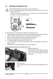
Locate an expansion slot that came with the slot, and press down on the card until it is fully inserted into the slot. 4. Install the driver provided with a screw. 5. PCI Express x1 Slot PCI Express x16 Slot PCI Slot Follow the steps below to make any required BIOS changes for your card. Carefully read the manual that supports your expansion card(s). 7. After installing all expansion cards, replace the chassis cover(s). 6. Remove the metal slot cover from the slot. Make sure the card is securely seated in your computer. Make sure the metal contacts on the card...
Locate an expansion slot that came with the slot, and press down on the card until it is fully inserted into the slot. 4. Install the driver provided with a screw. 5. PCI Express x1 Slot PCI Express x16 Slot PCI Slot Follow the steps below to make any required BIOS changes for your card. Carefully read the manual that supports your expansion card(s). 7. After installing all expansion cards, replace the chassis cover(s). 6. Remove the metal slot cover from the slot. Make sure the card is securely seated in your computer. Make sure the metal contacts on the card...
Manual
Page 19
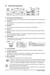
D-Sub Port The D-Sub port supports a 15-pin D-Sub connector. Use this audio jack for a headphone or 2-channel speaker. This jack can be connected to connect a PS/2 keyboard. RJ-45 LAN Port The Gigabit Ethernet LAN port provides Internet connection at up a 2/4/5.1/7.1-channel audio configuration in Chapter 5, "Configuring 2/4/5.1/7.1-Channel Audio." • When removing the cable connected to a back panel connector, first remove the cable from your device and then remove it from the motherboard. • When removing the cable, pull it side to side to connect front ...
D-Sub Port The D-Sub port supports a 15-pin D-Sub connector. Use this audio jack for a headphone or 2-channel speaker. This jack can be connected to connect a PS/2 keyboard. RJ-45 LAN Port The Gigabit Ethernet LAN port provides Internet connection at up a 2/4/5.1/7.1-channel audio configuration in Chapter 5, "Configuring 2/4/5.1/7.1-Channel Audio." • When removing the cable connected to a back panel connector, first remove the cable from your device and then remove it from the motherboard. • When removing the cable, pull it side to side to connect front ...
Manual
Page 20
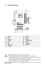
Unplug the power cord from the power outlet to prevent damage to the devices. • After installing the device and before connecting external devices: • First make sure the device cable has been securely attached to turn off the devices and your devices are compliant with the connectors you wish to connect. • Before installing the devices, be sure to the connector on the motherboard. 1-7 Internal Connectors 1 3 6 2 13 9 15 8 14 1011 5 4 12 7 1) ATX_12V 2) ATX 3) CPU_FAN 4) SYS_FAN 5) FDD 6) IDE 7) SATA2_0/1/2/3 8) F_PANEL 9) 10) 11) 12) 13) 14) 15) ...
Unplug the power cord from the power outlet to prevent damage to the devices. • After installing the device and before connecting external devices: • First make sure the device cable has been securely attached to turn off the devices and your devices are compliant with the connectors you wish to connect. • Before installing the devices, be sure to the connector on the motherboard. 1-7 Internal Connectors 1 3 6 2 13 9 15 8 14 1011 5 4 12 7 1) ATX_12V 2) ATX 3) CPU_FAN 4) SYS_FAN 5) FDD 6) IDE 7) SATA2_0/1/2/3 8) F_PANEL 9) 10) 11) 12) 13) 14) 15) ...