Manual
Page 4
Table of Contents Box Contents ...6 OptionalItems ...6 GA-EP45-DS5 Motherboard Layout 7 Block Diagram ...8 Chapter 1 Hardware Installation 9 1-1 Installation Precautions 9 1-2 Product Specifications 10 1-3 Installing the CPU and CPU Cooler 13 1-3-1...Channel Memory Configuration 16 1-4-2 Installing a Memory 17 1-5 Installing an Expansion Card 18 1-6 Installing the SATA Bracket 19 1-7 Back Panel Connectors 20 1-8 Onboard LEDs and Switches 22 1-9 Internal Connectors 23 Chapter 2 BIOS Setup 35 2-1 Startup Screen 36 2-2 The Main Menu 37 2-3 MB Intelligent Tweaker(M.I.T 39 2-4 Standard...
Table of Contents Box Contents ...6 OptionalItems ...6 GA-EP45-DS5 Motherboard Layout 7 Block Diagram ...8 Chapter 1 Hardware Installation 9 1-1 Installation Precautions 9 1-2 Product Specifications 10 1-3 Installing the CPU and CPU Cooler 13 1-3-1...Channel Memory Configuration 16 1-4-2 Installing a Memory 17 1-5 Installing an Expansion Card 18 1-6 Installing the SATA Bracket 19 1-7 Back Panel Connectors 20 1-8 Onboard LEDs and Switches 22 1-9 Internal Connectors 23 Chapter 2 BIOS Setup 35 2-1 Startup Screen 36 2-2 The Main Menu 37 2-3 MB Intelligent Tweaker(M.I.T 39 2-4 Standard...
Manual
Page 7
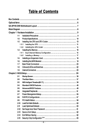
...LED ACPI_LED (S0/1/3/4/5_LED) PWR_FAN GA-EP45-DS5 Motherboard Layout KB_MS CPU_LED R_SPDIF USB_1394_1 ATX_12V_2X LGA775 CPU_FAN USB_1394_2 DIMM_LED USB_LAN2 ATX USB_LAN1 RTL8111C F_AUDIO AUDIO BAT PCIEX1_1 PE1_LED GD1 GD2 RTL8111C PCIEX1_2 PCIEX16 Intel® P45 PE_LED DDR2_1 DDR2_2 DDR2_3 DDR2_4 MD2 MD1 FDD CODEC PCIEX1_3 SPDIF_I CD_IN CI SPDIF_O PCI1 IT8720 PCI2 COMA GA-EP45-DS5... PCIEX8 TSB43AB23 PCI_LED Intel® ICH10R SA_LED SYS_FAN1 M_BIOS B_BIOS GIGABYTE SATA2 IDE SiI5723 SiI5723 SATA2_1 SATA2_0...
...LED ACPI_LED (S0/1/3/4/5_LED) PWR_FAN GA-EP45-DS5 Motherboard Layout KB_MS CPU_LED R_SPDIF USB_1394_1 ATX_12V_2X LGA775 CPU_FAN USB_1394_2 DIMM_LED USB_LAN2 ATX USB_LAN1 RTL8111C F_AUDIO AUDIO BAT PCIEX1_1 PE1_LED GD1 GD2 RTL8111C PCIEX1_2 PCIEX16 Intel® P45 PE_LED DDR2_1 DDR2_2 DDR2_3 DDR2_4 MD2 MD1 FDD CODEC PCIEX1_3 SPDIF_I CD_IN CI SPDIF_O PCI1 IT8720 PCI2 COMA GA-EP45-DS5... PCIEX8 TSB43AB23 PCI_LED Intel® ICH10R SA_LED SYS_FAN1 M_BIOS B_BIOS GIGABYTE SATA2 IDE SiI5723 SiI5723 SATA2_1 SATA2_0...

Manual
Page 11
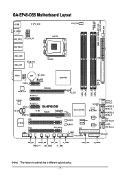
... Š 1 x S/PDIF In header Š 1 x S/PDIF Out header Š 2 x USB 2.0/1.1 headers Š 1 x IEEE 1394a header Š 1 x serial port header Š 1 x chassis intrusion header Š 1 x power LED header Š 1 x power switch Š 1 x reset switch Š 1 x clearing CMOS switch Back Panel Š 1 x PS/2 keyboard port Connectors Š 1 x PS/2 mouse port Š 1 x optical S/PDIF...
... Š 1 x S/PDIF In header Š 1 x S/PDIF Out header Š 2 x USB 2.0/1.1 headers Š 1 x IEEE 1394a header Š 1 x serial port header Š 1 x chassis intrusion header Š 1 x power LED header Š 1 x power switch Š 1 x reset switch Š 1 x clearing CMOS switch Back Panel Š 1 x PS/2 keyboard port Connectors Š 1 x PS/2 mouse port Š 1 x optical S/PDIF...
Manual
Page 20
... The USB port supports the USB 2.0/1.1 specification. Connection/ Speed LED Activity LED LAN Port Connection/Speed LED: State Description Orange 1 Gbps data rate Green 100 Mbps data rate Off 10 Mbps data rate Activity LED: State Description Blinking Data transmission or receiving is occurring Off No..., USB flash drive and etc. RJ-45 LAN Port The Gigabit Ethernet LAN port provides Internet connection at up to connect a PS/2 keyboard. GA-EP45-DS5 Motherboard - 20 - 1-7 Back Panel Connectors PS/2 Keyboard and PS/2 Mouse Port Use the upper port (green) to connect a PS/2 mouse...
... The USB port supports the USB 2.0/1.1 specification. Connection/ Speed LED Activity LED LAN Port Connection/Speed LED: State Description Orange 1 Gbps data rate Green 100 Mbps data rate Off 10 Mbps data rate Activity LED: State Description Blinking Data transmission or receiving is occurring Off No..., USB flash drive and etc. RJ-45 LAN Port The Gigabit Ethernet LAN port provides Internet connection at up to connect a PS/2 keyboard. GA-EP45-DS5 Motherboard - 20 - 1-7 Back Panel Connectors PS/2 Keyboard and PS/2 Mouse Port Use the upper port (green) to connect a PS/2 mouse...

Manual
Page 22
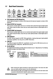
CPU Memory PCIe x8/x16 PCIe x1 PCI IDE SATA ACPI LEDs The 4 embedded ACPI LEDs indicate the system power status (S0, S1, S3, S4, S5) to prevent potential hardware damage due to quickly turn on/off or reset ... the components/devices have a problem. The 7 LEDs indicate if a component (including CPU and memory) or a device (including PCI and PCIe cards and IDE/SATA devices) works abnormally. Power Switch Reset Switch Clearing CMOS Switch GA-EP45-DS5 Motherboard - 22 - 1-8 Onboard LEDs and Switches Diagnostic LEDs This motherboard has 7 onboard LEDs controlled by the system BIOS.
CPU Memory PCIe x8/x16 PCIe x1 PCI IDE SATA ACPI LEDs The 4 embedded ACPI LEDs indicate the system power status (S0, S1, S3, S4, S5) to prevent potential hardware damage due to quickly turn on/off or reset ... the components/devices have a problem. The 7 LEDs indicate if a component (including CPU and memory) or a device (including PCI and PCIe cards and IDE/SATA devices) works abnormally. Power Switch Reset Switch Clearing CMOS Switch GA-EP45-DS5 Motherboard - 22 - 1-8 Onboard LEDs and Switches Diagnostic LEDs This motherboard has 7 onboard LEDs controlled by the system BIOS.
Manual
Page 23
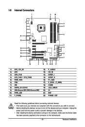
... 11) F_PANEL 12) F_AUDIO 13) CD_IN 14) SPDIF_I 15) SPDIF_O 16) F1_1394 17) F_USB1 / F_USB2 18) COMA 19) CLR_CMOS 20) CI 21) BAT 22) PHASE LED Read the following guidelines before turning on the computer, make sure your devices are compliant with the connectors you wish to connect. • Before installing...
... 11) F_PANEL 12) F_AUDIO 13) CD_IN 14) SPDIF_I 15) SPDIF_O 16) F1_1394 17) F_USB1 / F_USB2 18) COMA 19) CLR_CMOS 20) CI 21) BAT 22) PHASE LED Read the following guidelines before turning on the computer, make sure your devices are compliant with the connectors you wish to connect. • Before installing...
Manual
Page 27
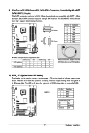
... conform to indicate system power status. Each SATA connector supports a single SATA device. The LED keeps blinking when the system is operating. System Status LED S0 On S1 Blinking S3/S4/S5 Off - 27 - Definition 1 1 MPD+ 2 MPD- 3 MPD- The GIGABYTE SATA2/SiI5723 controllers support Smart Backup Function. 7 7 1 GS3 1 GS1 GS0-Source 1 7 GS2-Source...
... conform to indicate system power status. Each SATA connector supports a single SATA device. The LED keeps blinking when the system is operating. System Status LED S0 On S1 Blinking S3/S4/S5 Off - 27 - Definition 1 1 MPD+ 2 MPD- 3 MPD- The GIGABYTE SATA2/SiI5723 controllers support Smart Backup Function. 7 7 1 GS3 1 GS1 GS0-Source 1 7 GS2-Source...
Manual
Page 28
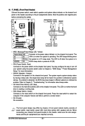
...) Connects to the reset switch on the chassis front panel. If a problem is in S1 sleep state. The LED is on when the hard drive is operating. GA-EP45-DS5 Motherboard - 28 - The LED keeps blinking when S1 Blinking the system is detected at system startup. Refer to Chapter 5, "Troubleshooting," for more information). • SPEAK...
...) Connects to the reset switch on the chassis front panel. If a problem is in S1 sleep state. The LED is on when the hard drive is operating. GA-EP45-DS5 Motherboard - 28 - The LED keeps blinking when S1 Blinking the system is detected at system startup. Refer to Chapter 5, "Troubleshooting," for more information). • SPEAK...
Manual
Page 34
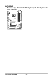
The higher the CPU loading, the more the number of lighted LEDs indicates the CPU loading. 22) PHASE LED The number of lighted LEDs. GA-EP45-DS5 Motherboard - 34 -
The higher the CPU loading, the more the number of lighted LEDs indicates the CPU loading. 22) PHASE LED The number of lighted LEDs. GA-EP45-DS5 Motherboard - 34 -
Manual
Page 55
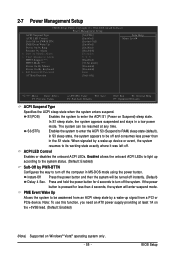
...state, the system appears to be off . 2-7 Power Management Setup CMOS Setup Utility-Copyright (C) 1984-2008 Award Software Power Management Setup ACPI Suspend Type ACPI LED Control Soft-Off by PWR-BTTN PME Event Wake Up Power On by Ring Resume by a wake-up device or event, the system resumes to... S3(STR) mode. BIOS Setup Note: To use this function, you need an ATX power supply providing at any time. Enabled allows the onboard ACPI LEDs to light up according to the system status. (Default: Enabled) Soft-Off by a wake-up signal from an ACPI sleep state by Alarm x Date (...
...state, the system appears to be off . 2-7 Power Management Setup CMOS Setup Utility-Copyright (C) 1984-2008 Award Software Power Management Setup ACPI Suspend Type ACPI LED Control Soft-Off by PWR-BTTN PME Event Wake Up Power On by Ring Resume by a wake-up device or event, the system resumes to... S3(STR) mode. BIOS Setup Note: To use this function, you need an ATX power supply providing at any time. Enabled allows the onboard ACPI LEDs to light up according to the system status. (Default: Enabled) Soft-Off by a wake-up signal from an ACPI sleep state by Alarm x Date (...

Manual
Page 79
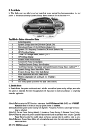
... model. • CPU Power and Power Scores are for reference only. Featuring an advanced proprietary hardware and software design, GIGABYTE Dynamic Energy Saver Advanced is a revolutionary technology that delivers unparalleled power savings with a click of time. Button Information Table... Button Description 1 Dynamic Energy Saver On/Off Switch (Default: Off) 2 Motherboard Phase LED On/Off Switch (Default: On) 3 Dynamic CPU Frequency Function On/Off Switch (Default: Off) (Note 2) 4 CPU Throttling Display 5 3-Level...
... model. • CPU Power and Power Scores are for reference only. Featuring an advanced proprietary hardware and software design, GIGABYTE Dynamic Energy Saver Advanced is a revolutionary technology that delivers unparalleled power savings with a click of time. Button Information Table... Button Description 1 Dynamic Energy Saver On/Off Switch (Default: Off) 2 Motherboard Phase LED On/Off Switch (Default: On) 3 Dynamic CPU Frequency Function On/Off Switch (Default: Off) (Note 2) 4 CPU Throttling Display 5 3-Level...
Manual
Page 80
... (Check for the first time (Note 4). Button Information Table Button Description 1 Dynamic Energy Saver On/Off Switch (Default: Off) 2 Motherboard Phase LED On/Off Switch (Default: On) 3 Dynamic CPU Frequency Function On/Off Switch (Default: Off) 4 CPU Throttling Display 5 3-Level CPU Voltage ... CPU Power Consumption 9 Time/Date Dynamic Energy Saver Enabled 10 Total Power Savings (Total power saving with Dynamic Frequency Function; GA-EP45-DS5 Motherboard - 80 - system performance may be recorded until re-activated when only the Dynamic Power Saver is under the enable ...
... (Check for the first time (Note 4). Button Information Table Button Description 1 Dynamic Energy Saver On/Off Switch (Default: Off) 2 Motherboard Phase LED On/Off Switch (Default: On) 3 Dynamic CPU Frequency Function On/Off Switch (Default: Off) 4 CPU Throttling Display 5 3-Level CPU Voltage ... CPU Power Consumption 9 Time/Date Dynamic Energy Saver Enabled 10 Total Power Savings (Total power saving with Dynamic Frequency Function; GA-EP45-DS5 Motherboard - 80 - system performance may be recorded until re-activated when only the Dynamic Power Saver is under the enable ...


