
Manual
Page 4
... the Infineon TPM driver. 2.2. Click the Install button on the "Xpress Install" main menu to install. Installing the Infineon TPM Driver Insert the GIGABYTE motherboard driver disk. Some motherboard driver disks include the Smart TPM utility in "Xpress Install." Installing the Infineon TPM Driver and the Smart TPM Utility Before you 'll be...
... the Infineon TPM driver. 2.2. Click the Install button on the "Xpress Install" main menu to install. Installing the Infineon TPM Driver Insert the GIGABYTE motherboard driver disk. Some motherboard driver disks include the Smart TPM utility in "Xpress Install." Installing the Infineon TPM Driver and the Smart TPM Utility Before you 'll be...

Manual
Page 7
.... Upon completing the steps above, click OK to use as the portable Smart TPM user key. Before creating a Bluetooth cell phone key, make sure your motherboard includes a Bluetooth receiver and turn on the search and Bluetooth functions on your cell phone for the Bluetooth enabled cell phone(s). Step 3: Create Your Smart...
.... Upon completing the steps above, click OK to use as the portable Smart TPM user key. Before creating a Bluetooth cell phone key, make sure your motherboard includes a Bluetooth receiver and turn on the search and Bluetooth functions on your cell phone for the Bluetooth enabled cell phone(s). Step 3: Create Your Smart...

Manual
Page 19
...'t display your Bluetooth-enabled cell phone, click Refresh to let Smart TPM re-detect the device.) Before creating a Bluetooth cell phone key, make sure your motherboard includes a Bluetooth receiver and turn off or reset your computer when a USB key is being created. • If you enter the TPM User Password incorrectly...
...'t display your Bluetooth-enabled cell phone, click Refresh to let Smart TPM re-detect the device.) Before creating a Bluetooth cell phone key, make sure your motherboard includes a Bluetooth receiver and turn off or reset your computer when a USB key is being created. • If you enter the TPM User Password incorrectly...
Manual
Page 3
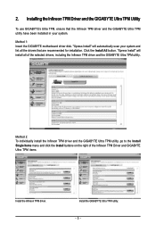
Method 1: Insert the GIGABYTE motherboard driver disk. "Xpress Install" will install all the drivers that the Infineon TPM driver and the GIGABYTE Ultra TPM utility have been installed in your system and list all of the Infineon TPM Driver and GIGABYTE Ultra TPM items. Install the Infineon TPM driver.... 2. Installing the Infineon TPM Driver and the GIGABYTE Ultra TPM Utility To use GIGABYTE's Ultra TPM, ensure that are recommended for installation. "Xpress Install"...
Method 1: Insert the GIGABYTE motherboard driver disk. "Xpress Install" will install all the drivers that the Infineon TPM driver and the GIGABYTE Ultra TPM utility have been installed in your system and list all of the Infineon TPM Driver and GIGABYTE Ultra TPM items. Install the Infineon TPM driver.... 2. Installing the Infineon TPM Driver and the GIGABYTE Ultra TPM Utility To use GIGABYTE's Ultra TPM, ensure that are recommended for installation. "Xpress Install"...
Manual
Page 1
GA-EP45-DS5 LGA775 socket motherboard for Intel® CoreTM processor family/ Intel® Pentium® processor family/Intel® Celeron® processor family User's Manual Rev. 1004 12ME-EP45DS5-1004R
GA-EP45-DS5 LGA775 socket motherboard for Intel® CoreTM processor family/ Intel® Pentium® processor family/Intel® Celeron® processor family User's Manual Rev. 1004 12ME-EP45DS5-1004R

Manual
Page 2
Motherboard GA-EP45-DS5 May 15, 2008 Motherboard GA-EP45-DS5 May 15, 2008
Motherboard GA-EP45-DS5 May 15, 2008 Motherboard GA-EP45-DS5 May 15, 2008
Manual
Page 3
...logo is 1.0. sive global distributor of this manual are legally registered to GIGABYTE UNITED INC. No part of GIGABYTE branded motherboards. Documentation Classifications In order to assist in the use GIGABYTE's unique features, read the User's Manual. „ For instructions on... the information on/from the Support\Motherboard\Technology Guide page on your motherboard revision before updating motherboard BIOS, drivers, or when looking for technical information. by GIGABYTE without GIGABYTE's prior written permission. Check your motherboard looks like this manual is protected by...
...logo is 1.0. sive global distributor of this manual are legally registered to GIGABYTE UNITED INC. No part of GIGABYTE branded motherboards. Documentation Classifications In order to assist in the use GIGABYTE's unique features, read the User's Manual. „ For instructions on... the information on/from the Support\Motherboard\Technology Guide page on your motherboard revision before updating motherboard BIOS, drivers, or when looking for technical information. by GIGABYTE without GIGABYTE's prior written permission. Check your motherboard looks like this manual is protected by...
Manual
Page 4
Table of Contents Box Contents ...6 OptionalItems ...6 GA-EP45-DS5 Motherboard Layout 7 Block Diagram ...8 Chapter 1 Hardware Installation 9 1-1 Installation Precautions 9 1-2 Product Specifications 10 1-3 Installing the CPU and CPU Cooler 13 1-3-1 Installing the CPU 13 1-3-2 Installing the CPU ...
Table of Contents Box Contents ...6 OptionalItems ...6 GA-EP45-DS5 Motherboard Layout 7 Block Diagram ...8 Chapter 1 Hardware Installation 9 1-1 Installation Precautions 9 1-2 Product Specifications 10 1-3 Installing the CPU and CPU Cooler 13 1-3-1 Installing the CPU 13 1-3-2 Installing the CPU ...
Manual
Page 6
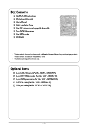
Box Contents GA-EP45-DS5 motherboard Motherboard driver disk User's Manual Quick Installation Guide One IDE cable and one floppy disk drive cable Four SATA 3Gb/s cables One SATA bracket I/O Shield • The box contents above are subject to change without notice. • The motherboard image is for reference only and the actual items shall depend on...
Box Contents GA-EP45-DS5 motherboard Motherboard driver disk User's Manual Quick Installation Guide One IDE cable and one floppy disk drive cable Four SATA 3Gb/s cables One SATA bracket I/O Shield • The box contents above are subject to change without notice. • The motherboard image is for reference only and the actual items shall depend on...
Manual
Page 7
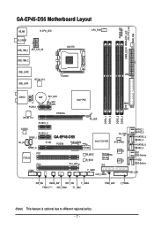
...GA-EP45-DS5 Motherboard Layout KB_MS CPU_LED R_SPDIF USB_1394_1 ATX_12V_2X LGA775 CPU_FAN USB_1394_2 DIMM_LED USB_LAN2 ATX USB_LAN1 RTL8111C F_AUDIO AUDIO BAT PCIEX1_1 PE1_LED GD1 GD2 RTL8111C PCIEX1_2 PCIEX16 Intel® P45 PE_LED DDR2_1 DDR2_2 DDR2_3 DDR2_4 MD2 MD1 FDD CODEC PCIEX1_3 SPDIF_I CD_IN CI SPDIF_O PCI1 IT8720 PCI2 COMA GA-EP45-DS5... PCIEX8 TSB43AB23 PCI_LED Intel® ICH10R SA_LED SYS_FAN1 M_BIOS B_BIOS GIGABYTE SATA2 IDE SiI5723 SiI5723 SATA2_1 SATA2_0 SATA2_3 SATA2_2 ...
...GA-EP45-DS5 Motherboard Layout KB_MS CPU_LED R_SPDIF USB_1394_1 ATX_12V_2X LGA775 CPU_FAN USB_1394_2 DIMM_LED USB_LAN2 ATX USB_LAN1 RTL8111C F_AUDIO AUDIO BAT PCIEX1_1 PE1_LED GD1 GD2 RTL8111C PCIEX1_2 PCIEX16 Intel® P45 PE_LED DDR2_1 DDR2_2 DDR2_3 DDR2_4 MD2 MD1 FDD CODEC PCIEX1_3 SPDIF_I CD_IN CI SPDIF_O PCI1 IT8720 PCI2 COMA GA-EP45-DS5... PCIEX8 TSB43AB23 PCI_LED Intel® ICH10R SA_LED SYS_FAN1 M_BIOS B_BIOS GIGABYTE SATA2 IDE SiI5723 SiI5723 SATA2_1 SATA2_0 SATA2_3 SATA2_2 ...
Manual
Page 9
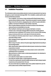
... the computer system in a high-temperature environment. • Turning on the computer power during the installation process can become damaged as a motherboard, CPU or memory. Hardware Installation These stickers are uncertain about any metal leads or connectors. • It is best to installation, do... the product, please verify that all cables and power connectors of your hardware components are connected. • To prevent damage to the motherboard, do not have an ESD wrist strap, keep your dealer. Prior to installation, carefully read the user's manual and follow these procedures...
... the computer system in a high-temperature environment. • Turning on the computer power during the installation process can become damaged as a motherboard, CPU or memory. Hardware Installation These stickers are uncertain about any metal leads or connectors. • It is best to installation, do... the product, please verify that all cables and power connectors of your hardware components are connected. • To prevent damage to the motherboard, do not have an ESD wrist strap, keep your dealer. Prior to installation, carefully read the user's manual and follow these procedures...
Manual
Page 10
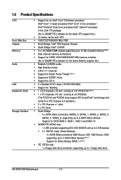
... connector supporting up to 4 SATA 3Gb/s devices (Note 4) - Support for SATA RAID 0, RAID 1, RAID 5 and RAID 10 Š GIGABYTE SATA2 chip: - 1 x IDE connector supporting ATA-133/100/66/33 and up to 2 IDE devices Š 2 x SiI5723 chips (...Dual channel memory architecture Š Support for DDR2 1200/1066/800/667 MHz memory modules (Go to GIGABYTE's website for the latest memory support list.) Š Realtek ALC889A codec Š High Definition Audio &#...connectors (SATA2_0, SATA2_1, SATA2_2, SATA2_3, SATA2_4, SATA2_5) supporting up to 1 floppy disk drive GA-EP45-DS5 Motherboard - 10 -
... connector supporting up to 4 SATA 3Gb/s devices (Note 4) - Support for SATA RAID 0, RAID 1, RAID 5 and RAID 10 Š GIGABYTE SATA2 chip: - 1 x IDE connector supporting ATA-133/100/66/33 and up to 2 IDE devices Š 2 x SiI5723 chips (...Dual channel memory architecture Š Support for DDR2 1200/1066/800/667 MHz memory modules (Go to GIGABYTE's website for the latest memory support list.) Š Realtek ALC889A codec Š High Definition Audio &#...connectors (SATA2_0, SATA2_1, SATA2_2, SATA2_3, SATA2_4, SATA2_5) supporting up to 1 floppy disk drive GA-EP45-DS5 Motherboard - 10 -

Manual
Page 12
... BIOS Setup to enable the Smart Backup function. The second hard drive must have equal or larger capacity than the first hard drive, i.e. GA-EP45-DS5 Motherboard - 12 - When two graphics cards are installed, the PCIEX16 slot will operate at up the data on the CPU/ system cooler you ...4 GB of physical memory is to be installed, please connect it to the GS0-Source or GS2-Source connector, or the system may differ by motherboard model. (Note 8) This feature is optional due to Chapter 2, "BIOS Setup," "Integrated Peripherals," for optimum performance. hard drive connected to two ...
... BIOS Setup to enable the Smart Backup function. The second hard drive must have equal or larger capacity than the first hard drive, i.e. GA-EP45-DS5 Motherboard - 12 - When two graphics cards are installed, the PCIEX16 slot will operate at up the data on the CPU/ system cooler you ...4 GB of physical memory is to be installed, please connect it to the GS0-Source or GS2-Source connector, or the system may differ by motherboard model. (Note 8) This feature is optional due to Chapter 2, "BIOS Setup," "Integrated Peripherals," for optimum performance. hard drive connected to two ...

Manual
Page 13
Locate the alignment keys on the motherboard CPU socket and the notches on the CPU - 13 - Hardware Installation 1-3 Installing the CPU and CPU Cooler Read the following guidelines before you begin to ... power outlet before installing the CPU to your hardware specifications including the CPU, graphics card, memory, hard drive, etc. 1-3-1 Installing the CPU A. mended that the motherboard supports the CPU. (Go to GIGABYTE's website for the peripherals.
Locate the alignment keys on the motherboard CPU socket and the notches on the CPU - 13 - Hardware Installation 1-3 Installing the CPU and CPU Cooler Read the following guidelines before you begin to ... power outlet before installing the CPU to your hardware specifications including the CPU, graphics card, memory, hard drive, etc. 1-3-1 Installing the CPU A. mended that the motherboard supports the CPU. (Go to GIGABYTE's website for the peripherals.
Manual
Page 14
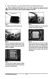
... the protective socket cover when the CPU is properly inserted, replace the load plate and push the CPU socket lever back into its locked position. GA-EP45-DS5 Motherboard - 14 - Step 2: Lift the metal load plate from the CPU socket. (DO NOT touch socket contacts.) Step 3: Remove the protective socket cover from the power... the CPU. B. Step 5: Once the CPU is not installed.) Step 4: Hold the CPU with the socket alignment keys) and gently insert the CPU into the motherboard CPU socket.
... the protective socket cover when the CPU is properly inserted, replace the load plate and push the CPU socket lever back into its locked position. GA-EP45-DS5 Motherboard - 14 - Step 2: Lift the metal load plate from the CPU socket. (DO NOT touch socket contacts.) Step 3: Remove the protective socket cover from the power... the CPU. B. Step 5: Once the CPU is not installed.) Step 4: Hold the CPU with the socket alignment keys) and gently insert the CPU into the motherboard CPU socket.
Manual
Page 15
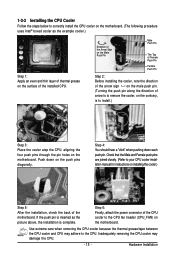
...pin holes on the contrary, is complete. Hardware Installation 1-3-2 Installing the CPU Cooler Follow the steps below to correctly install the CPU cooler on the motherboard. (The following procedure uses Intel® boxed cooler as the picture above, the installation is to the CPU. Step 4: You should hear a ..."click" when pushing down on the motherboard. Push down each push pin. Direction of the Arrow Sign on the Male Push Pin Male Push Pin The Top of Female Push Pin Female...
...pin holes on the contrary, is complete. Hardware Installation 1-3-2 Installing the CPU Cooler Follow the steps below to correctly install the CPU cooler on the motherboard. (The following procedure uses Intel® boxed cooler as the picture above, the installation is to the CPU. Step 4: You should hear a ..."click" when pushing down on the motherboard. Push down each push pin. Direction of the Arrow Sign on the Male Push Pin Male Push Pin The Top of Female Push Pin Female...
Manual
Page 16
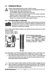
... be used . (Go to GIGABYTE's website for optimum performance. When memory modules of the same capacity, brand, speed, and chips be populated and remain in Dual Channel mode. 1. It is recommended that memory of the memory. DS/SS - - - - Dual Channel mode cannot be enabled if only one direction. GA-EP45-DS5 Motherboard - 16 - 1-4 Installing the...
... be used . (Go to GIGABYTE's website for optimum performance. When memory modules of the same capacity, brand, speed, and chips be populated and remain in Dual Channel mode. 1. It is recommended that memory of the memory. DS/SS - - - - Dual Channel mode cannot be enabled if only one direction. GA-EP45-DS5 Motherboard - 16 - 1-4 Installing the...

Manual
Page 17
... , make sure to turn off the computer and unplug the power cord from the power outlet to prevent damage to install DDR2 DIMMs on this motherboard. DDR2 DIMMs are not compatible to DDR DIMMs. Be sure to the memory module.
... , make sure to turn off the computer and unplug the power cord from the power outlet to prevent damage to install DDR2 DIMMs on this motherboard. DDR2 DIMMs are not compatible to DDR DIMMs. Be sure to the memory module.
Manual
Page 18
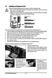
Turn on your operating system. Make sure the card is fully inserted into the slot. 4. GA-EP45-DS5 Motherboard - 18 - • Removing the Card from the PCIEX8 slot: Press the white latch at the end of the card until it is securely seated in ... the slot and then lift the card straight out from the power outlet before you begin to install an expansion card: • Make sure the motherboard supports the expansion card. Make sure the metal contacts on the top edge of the PCI Express slot to release the card and then pull...
Turn on your operating system. Make sure the card is fully inserted into the slot. 4. GA-EP45-DS5 Motherboard - 18 - • Removing the Card from the PCIEX8 slot: Press the white latch at the end of the card until it is securely seated in ... the slot and then lift the card straight out from the power outlet before you begin to install an expansion card: • Make sure the motherboard supports the expansion card. Make sure the metal contacts on the top edge of the PCI Express slot to release the card and then pull...

Manual
Page 19
... off your system and the power switch on your SATA device. the external SATA con- Before connecting the SATA signal cable, make sure to your motherboard. SATA Bracket SATA Signal Cable SATA Power Cable External SATA Connector Power Connector External SATA Connector The SATA bracket includes one SATA bracket, one SATA...
... off your system and the power switch on your SATA device. the external SATA con- Before connecting the SATA signal cable, make sure to your motherboard. SATA Bracket SATA Signal Cable SATA Power Cable External SATA Connector Power Connector External SATA Connector The SATA bracket includes one SATA bracket, one SATA...


