Manual
Page 4
... ...6 GA-EP45-DS5 Motherboard Layout 7 Block Diagram ...8 Chapter 1 Hardware Installation 9 1-1 Installation Precautions 9 1-2 Product Specifications 10 1-3 Installing the CPU and CPU Cooler 13 1-3-1 Installing the CPU 13 1-3-2 Installing the CPU Cooler 15 1-4 Installing the Memory 16 1-4-1 Dual Channel Memory Configuration 16 1-4-2 Installing a Memory 17 1-5 Installing an Expansion Card 18 1-6 Installing the SATA Bracket 19 1-7 Back Panel Connectors 20 1-8 Onboard LEDs and Switches 22 1-9 Internal Connectors 23 Chapter 2 BIOS Setup 35 2-1 Startup Screen 36 2-2 The Main Menu...
... ...6 GA-EP45-DS5 Motherboard Layout 7 Block Diagram ...8 Chapter 1 Hardware Installation 9 1-1 Installation Precautions 9 1-2 Product Specifications 10 1-3 Installing the CPU and CPU Cooler 13 1-3-1 Installing the CPU 13 1-3-2 Installing the CPU Cooler 15 1-4 Installing the Memory 16 1-4-1 Dual Channel Memory Configuration 16 1-4-2 Installing a Memory 17 1-5 Installing an Expansion Card 18 1-6 Installing the SATA Bracket 19 1-7 Back Panel Connectors 20 1-8 Onboard LEDs and Switches 22 1-9 Internal Connectors 23 Chapter 2 BIOS Setup 35 2-1 Startup Screen 36 2-2 The Main Menu...
Manual
Page 10
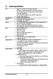
... memory support list.) Š Realtek ALC889A codec Š High Definition Audio Š 2/4/5.1/7.1-channel Š Support for Dolby® Home Theater (Note 2) Š Support for S/PDIF In/Out Š Support for CD In Š 2 x Realtek 8111C chips (10/100/1000 Mbit) Š Support for Smart Backup (RAID 1) (Note 5) Š iTE IT8720 chip: - 1 x floppy disk drive connector supporting up to 1 floppy disk drive GA-EP45-DS5 Motherboard - 10 - Support for Teaming Š 1 x PCI Express x16 slot, running at x16 (PCIEX16) (Note 3) Š 1 x PCI Express...
... memory support list.) Š Realtek ALC889A codec Š High Definition Audio Š 2/4/5.1/7.1-channel Š Support for Dolby® Home Theater (Note 2) Š Support for S/PDIF In/Out Š Support for CD In Š 2 x Realtek 8111C chips (10/100/1000 Mbit) Š Support for Smart Backup (RAID 1) (Note 5) Š iTE IT8720 chip: - 1 x floppy disk drive connector supporting up to 1 floppy disk drive GA-EP45-DS5 Motherboard - 10 - Support for Teaming Š 1 x PCI Express x16 slot, running at x16 (PCIEX16) (Note 3) Š 1 x PCI Express...

Manual
Page 12
... installed, the actual memory size displayed will be less than 4 GB. (Note 2) For Windows Vista/XP 32-bit operating system only. (Note 3) If you are installing one SATA hard drive is to be sure to enter BIOS Setup to set Smart Backup Initial to Enabled. (Refer to Chapter 2, "BIOS Setup," "Integrated Peripherals," for more information.) (Note 5) The Smart Backup function can back up to x8 mode. (Note 4) A SiI5723 chip supports two SATA 3Gb/s connectors...
... installed, the actual memory size displayed will be less than 4 GB. (Note 2) For Windows Vista/XP 32-bit operating system only. (Note 3) If you are installing one SATA hard drive is to be sure to enter BIOS Setup to set Smart Backup Initial to Enabled. (Refer to Chapter 2, "BIOS Setup," "Integrated Peripherals," for more information.) (Note 5) The Smart Backup function can back up to x8 mode. (Note 4) A SiI5723 chip supports two SATA 3Gb/s connectors...
Manual
Page 16
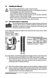
... DS/SS - - GA-EP45-DS5 Motherboard - 16 - If you begin to insert the memory, switch the direction. 1-4-1 Dual Channel Memory Configuration This motherboard provides four DDR2 memory sockets and supports Dual Channel Technology. The four DDR2 memory sockets are divided into two channels and each channel has two memory sockets as following guidelines before you are installed, a message which says memory is installed. 2. Intel® Flex Memory Technology offers greater flexibility to upgrade by allowing different memory sizes to prevent hardware...
... DS/SS - - GA-EP45-DS5 Motherboard - 16 - If you begin to insert the memory, switch the direction. 1-4-1 Dual Channel Memory Configuration This motherboard provides four DDR2 memory sockets and supports Dual Channel Technology. The four DDR2 memory sockets are divided into two channels and each channel has two memory sockets as following guidelines before you are installed, a message which says memory is installed. 2. Intel® Flex Memory Technology offers greater flexibility to upgrade by allowing different memory sizes to prevent hardware...
Manual
Page 18
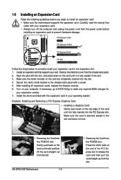
... installing all expansion cards, replace the chassis cover(s). 6. If necessary, go to BIOS Setup to make any required BIOS changes for your computer. Remove the metal slot cover from the slot. Turn on the card are completely inserted into the PCI Express slot. Secure the card's metal bracket to correctly install your expansion card. • Always turn off the computer and unplug the power cord from the slot. GA-EP45-DS5 Motherboard - 18 - • Removing the Card from...
... installing all expansion cards, replace the chassis cover(s). 6. If necessary, go to BIOS Setup to make any required BIOS changes for your computer. Remove the metal slot cover from the slot. Turn on the card are completely inserted into the PCI Express slot. Secure the card's metal bracket to correctly install your expansion card. • Always turn off the computer and unplug the power cord from the slot. GA-EP45-DS5 Motherboard - 18 - • Removing the Card from...
Manual
Page 32
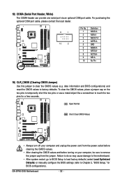
...; After clearing the CMOS values and before turning on the two pins to temporarily short the two pins or use a metal object like a screwdriver to touch the two pins for BIOS configurations). GA-EP45-DS5 Motherboard - 32 - Failure to do so may cause damage to the motherboard. • After system restart, go to BIOS Setup to load factory defaults (select Load Optimized Defaults) or manually configure the BIOS settings (refer to factory defaults. For purchasing the optional COM port cable...
...; After clearing the CMOS values and before turning on the two pins to temporarily short the two pins or use a metal object like a screwdriver to touch the two pins for BIOS configurations). GA-EP45-DS5 Motherboard - 32 - Failure to do so may cause damage to the motherboard. • After system restart, go to BIOS Setup to load factory defaults (select Load Optimized Defaults) or manually configure the BIOS settings (refer to factory defaults. For purchasing the optional COM port cable...
Manual
Page 36
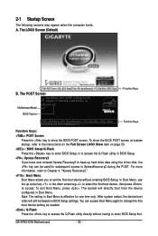
... on BIOS Setup settings. In Boot Menu, use the up hard drive data using the driver disk, the key can access Boot Menu again to change the first boot device setting as needed. : Q-Flash Press the key to access the Q-Flash utility directly without entering BIOS Setup. You can be based on page 50. : BIOS Setup/Q-Flash Press the key to enter BIOS Setup or to access the Q-Flash utility in Boot Menu. The POST Screen Award Modular BIOS v6.00PG, An Energy Star Ally Copyright (C) 1984-2008, Award Software, Inc. To exit Boot Menu, press . A. 2-1 Startup Screen...
... on BIOS Setup settings. In Boot Menu, use the up hard drive data using the driver disk, the key can access Boot Menu again to change the first boot device setting as needed. : Q-Flash Press the key to access the Q-Flash utility directly without entering BIOS Setup. You can be based on page 50. : BIOS Setup/Q-Flash Press the key to enter BIOS Setup or to access the Q-Flash utility in Boot Menu. The POST Screen Award Modular BIOS v6.00PG, An Energy Star Ally Copyright (C) 1984-2008, Award Software, Inc. To exit Boot Menu, press . A. 2-1 Startup Screen...
Manual
Page 38
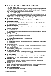
... CPU, memory, etc. „ Standard CMOS Features Use this menu to configure the system time and date, hard drive types, floppy disk drive types, and the type of errors that stop the system boot, etc. „ Advanced BIOS Features Use this menu to configure the device boot order, advanced features available on the CPU, and the primary display adapter. „ Integrated Peripherals Use this menu to configure all peripheral devices, such as IDE, SATA, USB, integrated audio, and integrated LAN, etc. „ Power Management Setup Use...
... CPU, memory, etc. „ Standard CMOS Features Use this menu to configure the system time and date, hard drive types, floppy disk drive types, and the type of errors that stop the system boot, etc. „ Advanced BIOS Features Use this menu to configure the device boot order, advanced features available on the CPU, and the primary display adapter. „ Integrated Peripherals Use this menu to configure all peripheral devices, such as IDE, SATA, USB, integrated audio, and integrated LAN, etc. „ Power Management Setup Use...

Manual
Page 40
... Clock Control CPU Host Clock Control Enables or disables the control of these components. The item is present only if a CPU with the overclock/overvoltage settings you install a CPU that supports this occurs, clear the CMOS values and reset the board to default values.) Robust Graphics Booster Robust Graphics Booster (R.G.B.) helps to alter the clock ratio for the installed CPU. CMOS Setup Utility-Copyright (C) 1984-2008 Award Software MB Intelligent Tweaker(M.I.T.) >>> MCH/ICH MCH Core MCH Reference MCH/DRAM Reference ICH I/O >>> DRAM DRAM Voltage DRAM...
... Clock Control CPU Host Clock Control Enables or disables the control of these components. The item is present only if a CPU with the overclock/overvoltage settings you install a CPU that supports this occurs, clear the CMOS values and reset the board to default values.) Robust Graphics Booster Robust Graphics Booster (R.G.B.) helps to alter the clock ratio for the installed CPU. CMOS Setup Utility-Copyright (C) 1984-2008 Award Software MB Intelligent Tweaker(M.I.T.) >>> MCH/ICH MCH Core MCH Reference MCH/DRAM Reference ICH I/O >>> DRAM DRAM Voltage DRAM...
Manual
Page 48
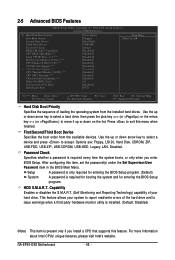
2-5 Advanced BIOS Features CMOS Setup Utility-Copyright (C) 1984-2008 Award Software Advanced BIOS Features ` Hard Disk Boot Priority First Boot Device [Press Enter] [Floppy] Item Help Menu Level` Second Boot Device Third Boot Device Password Check [Hard Disk] [CDROM] [Setup] HDD S.M.A.R.T. Use the up or down arrow key to select a device and press to 3 (Note) No-Execute Memory Protect (Note) CPU Enhanced Halt (C1E) (Note) C2/C2E State Support (Note) x C4/C4E State Support (Note) CPU Thermal Monitor 2(TM2) (Note) CPU EIST Function (Note) Virtualization Technology (Note...
2-5 Advanced BIOS Features CMOS Setup Utility-Copyright (C) 1984-2008 Award Software Advanced BIOS Features ` Hard Disk Boot Priority First Boot Device [Press Enter] [Floppy] Item Help Menu Level` Second Boot Device Third Boot Device Password Check [Hard Disk] [CDROM] [Setup] HDD S.M.A.R.T. Use the up or down arrow key to select a device and press to 3 (Note) No-Execute Memory Protect (Note) CPU Enhanced Halt (C1E) (Note) C2/C2E State Support (Note) x C4/C4E State Support (Note) CPU Thermal Monitor 2(TM2) (Note) CPU EIST Function (Note) Virtualization Technology (Note...
Manual
Page 54
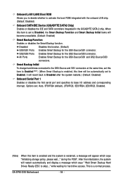
... Enabled . (Note) (When Smart Backup is set to activate the boot ROM integrated with the onboard LAN chip. (Default: Disabled) Onboard SATA/IDE Device (GIGABYTE SATA2 Chip) Enables or disables the IDE and SATA controllers integrated in the GIGABYTE SATA 2 chip. All Ports Enables Smart Backup for hard drive access. After the initialization, the system will revert back to skip)..." Smart Backup Initial To change hard drives connected to the GS0-Source and GS1 connectors at the same time, set this item will be automatically set to Disabled, the Smart...
... Enabled . (Note) (When Smart Backup is set to activate the boot ROM integrated with the onboard LAN chip. (Default: Disabled) Onboard SATA/IDE Device (GIGABYTE SATA2 Chip) Enables or disables the IDE and SATA controllers integrated in the GIGABYTE SATA 2 chip. All Ports Enables Smart Backup for hard drive access. After the initialization, the system will revert back to skip)..." Smart Backup Initial To change hard drives connected to the GS0-Source and GS1 connectors at the same time, set this item will be automatically set to Disabled, the Smart...
Manual
Page 55
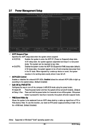
... awakened from a PCI or PCIe device. Instant-Off Press the power button and then the system will enter suspend mode. Enables the system to enter the ACPI S3 (Suspend to be resumed at least 1A on the +5VSB lead. (Default: Enabled) (Note) Supported on Suspend) sleep state. BIOS Setup 2-7 Power Management Setup CMOS Setup Utility-Copyright (C) 1984-2008 Award Software Power Management Setup ACPI Suspend Type ACPI LED Control Soft-Off by PWR-BTTN PME Event Wake Up Power On by Ring...
... awakened from a PCI or PCIe device. Instant-Off Press the power button and then the system will enter suspend mode. Enables the system to enter the ACPI S3 (Suspend to be resumed at least 1A on the +5VSB lead. (Default: Enabled) (Note) Supported on Suspend) sleep state. BIOS Setup 2-7 Power Management Setup CMOS Setup Utility-Copyright (C) 1984-2008 Award Software Power Management Setup ACPI Suspend Type ACPI LED Control Soft-Off by PWR-BTTN PME Event Wake Up Power On by Ring...
Manual
Page 59
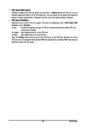
.... (Default: Enabled) CPU Smart FAN Mode Specifies how to control CPU fan speed. However, for a 4-pin CPU fan that is set for a 3-pin CPU fan or a 4-pin CPU fan. You can be set to the CPU temperature. This item is configurable only if CPU Smart FAN Control is not designed following Intel PWM fan specifications, selecting PWM mode may not effectively reduce the fan speed. - 59 - PWM Sets PWM mode for a 3-pin CPU fan. Note: The Voltage mode can adjust the fan speed with EasyTune based on system requirements. BIOS Setup CPU Smart FAN Control Enables or disables the CPU...
.... (Default: Enabled) CPU Smart FAN Mode Specifies how to control CPU fan speed. However, for a 4-pin CPU fan that is set for a 3-pin CPU fan or a 4-pin CPU fan. You can be set to the CPU temperature. This item is configurable only if CPU Smart FAN Control is not designed following Intel PWM fan specifications, selecting PWM mode may not effectively reduce the fan speed. - 59 - PWM Sets PWM mode for a 3-pin CPU fan. Note: The Voltage mode can adjust the fan speed with EasyTune based on system requirements. BIOS Setup CPU Smart FAN Control Enables or disables the CPU...
Manual
Page 74
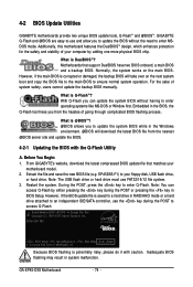
..., users cannot update the backup BIOS manually. From GIGABYTE's website, download the latest compressed BIOS update file that support DualBIOS have two BIOS onboard, a main BIOS and a backup BIOS. Note: You can update the system BIOS without the need to enter operating systems like MS-DOS or Window first. EP45DS5.F1) to enter Q-Flash. Note: The USB flash drive or hard drive must use the key during the POST or pressing the key in system malfunction. 4-2 BIOS Update Utilities GIGABYTE motherboards provide two unique BIOS update tools...
..., users cannot update the backup BIOS manually. From GIGABYTE's website, download the latest compressed BIOS update file that support DualBIOS have two BIOS onboard, a main BIOS and a backup BIOS. Note: You can update the system BIOS without the need to enter operating systems like MS-DOS or Window first. EP45DS5.F1) to enter Q-Flash. Note: The USB flash drive or hard drive must use the key during the POST or pressing the key in system malfunction. 4-2 BIOS Update Utilities GIGABYTE motherboards provide two unique BIOS update tools...
Manual
Page 75
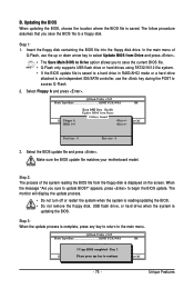
... remove the floppy disk, USB flash drive, or hard drive when the system is saved. Select the BIOS update file and press . CoUpypdBaItOe SBIcOomS pfrloetmedD-rPivaess !! appears, press to update BIOS?" Save BIOS to the main menu. Step 3: When the update process is saved to a hard drive in RAID/AHCI mode or a hard drive attached to an independent IDE/SATA controller, use the up or down arrow key to select Update BIOS from Drive Sa0vefilBeI(Os)SfotounDdrive KL:Move ESC:Reset :Power Off Total size : 0 Free size...
... remove the floppy disk, USB flash drive, or hard drive when the system is saved. Select the BIOS update file and press . CoUpypdBaItOe SBIcOomS pfrloetmedD-rPivaess !! appears, press to update BIOS?" Save BIOS to the main menu. Step 3: When the update process is saved to a hard drive in RAID/AHCI mode or a hard drive attached to an independent IDE/SATA controller, use the up or down arrow key to select Update BIOS from Drive Sa0vefilBeI(Os)SfotounDdrive KL:Move ESC:Reset :Power Off Total size : 0 Free size...
Manual
Page 78
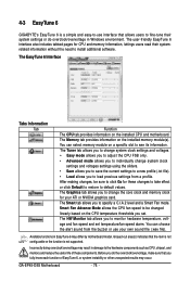
... install additional software. GA-EP45-DS5 Motherboard - 78 - The HW Monitor tab allows you to see its information. The user-friendly EasyTune 6 interface also includes tabbed pages for these components. 4-3 EasyTune 6 GIGABYTE's EasyTune 6 is not supported. The EasyTune 6 Interface Tabs Information Tab Function The CPU tab provides information on the installed memory module(s). After making changes, be changed linearly based on a specific slot to specify a C.I.A.2 level and a Smart Fan mode...
... install additional software. GA-EP45-DS5 Motherboard - 78 - The HW Monitor tab allows you to see its information. The user-friendly EasyTune 6 interface also includes tabbed pages for these components. 4-3 EasyTune 6 GIGABYTE's EasyTune 6 is not supported. The EasyTune 6 Interface Tabs Information Tab Function The CPU tab provides information on the installed memory module(s). After making changes, be changed linearly based on a specific slot to specify a C.I.A.2 level and a Smart Fan mode...
Manual
Page 87
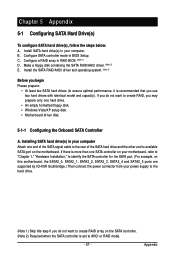
... SATA controller for the SATA port. (For example, on this motherboard, the SATA2_0, SATA2_1, SATA2_2, SATA2_3, SATA2_4 and SATA2_5 ports are supported by ICH10R Southbridge.) Then connect the power connector from your power supply to the hard drive. (Note 1) Skip this step if you do not want to ensure optimal performance, it is set to create RAID, you use two hard drives with identical model and capacity). Make a floppy disk containing the SATA RAID/AHCI driver...
... SATA controller for the SATA port. (For example, on this motherboard, the SATA2_0, SATA2_1, SATA2_2, SATA2_3, SATA2_4 and SATA2_5 ports are supported by ICH10R Southbridge.) Then connect the power connector from your power supply to the hard drive. (Note 1) Skip this step if you do not want to ensure optimal performance, it is set to create RAID, you use two hard drives with identical model and capacity). Make a floppy disk containing the SATA RAID/AHCI driver...
Manual
Page 95
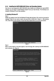
... files being loaded before you have prepared the SATA RAID/AHCI driver diskette and configured the required BIOS settings, you do not want to install a third party SCSI or RAID driver. S=Specify Additional Device ENTER=Continue F3=Exit Figure 2 - 95 - 5-1-3 Installing the SATA RAID/AHCI Driver and Operating System Now that below appears, insert the floppy disk containing the SATA RAID/AHCI driver and press (Figure 2). A. Currently, Setup will be a few moments of Windows XP and Vista installation. Installing Windows...
... files being loaded before you have prepared the SATA RAID/AHCI driver diskette and configured the required BIOS settings, you do not want to install a third party SCSI or RAID driver. S=Specify Additional Device ENTER=Continue F3=Exit Figure 2 - 95 - 5-1-3 Installing the SATA RAID/AHCI Driver and Operating System Now that below appears, insert the floppy disk containing the SATA RAID/AHCI driver and press (Figure 2). A. Currently, Setup will be a few moments of Windows XP and Vista installation. Installing Windows...
Manual
Page 103
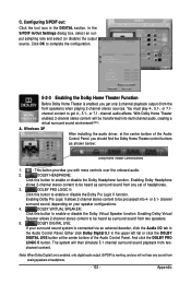
... surround sound from any sound from two- Windows XP After installing the audio driver, at the center bottom of the Audio Control Panel, you should find the Dolby Home Theater control buttons as shown below: Dolby Home Theater Control Buttons 1. : This button provides you will be heard as surround sound from two speakers. 5. channel surround sound, depending on your surround sound system is working, and you with more controls over the onboard audio. 2. channel...
... surround sound from any sound from two- Windows XP After installing the audio driver, at the center bottom of the Audio Control Panel, you should find the Dolby Home Theater control buttons as shown below: Dolby Home Theater Control Buttons 1. : This button provides you will be heard as surround sound from two speakers. 5. channel surround sound, depending on your surround sound system is working, and you with more controls over the onboard audio. 2. channel...
Manual
Page 107
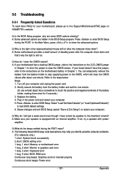
...computer problems. (For reference only.) 1 short: System boots successfully 2 short: CMOS setting error 1 long, 1 short: Memory or motherboard error 1 long, 2 short: Monitor or graphics card error 1 long, 3 short: Keyboard error 1 long, 9 short: BIOS ROM error Continuous long beeps: Graphics card not inserted properly Continuous short beeps: Power error - 107 - Q: In the BIOS Setup program, why are hidden in the power cord and restart your motherboard has a clearing CMOS jumper, refer to the instructions on GIGABYTE's website. If not, try a speaker with an internal amplifier. Plug in...
...computer problems. (For reference only.) 1 short: System boots successfully 2 short: CMOS setting error 1 long, 1 short: Memory or motherboard error 1 long, 2 short: Monitor or graphics card error 1 long, 3 short: Keyboard error 1 long, 9 short: BIOS ROM error Continuous long beeps: Graphics card not inserted properly Continuous short beeps: Power error - 107 - Q: In the BIOS Setup program, why are hidden in the power cord and restart your motherboard has a clearing CMOS jumper, refer to the instructions on GIGABYTE's website. If not, try a speaker with an internal amplifier. Plug in...


