Manual
Page 9
.... • Turning on the power, make sure they are connected tightly and securely. • When handling the motherboard, avoid touching any installation steps or have a problem related to the use of the product, please consult a certified computer technician. - 9 -
.... • Turning on the power, make sure they are connected tightly and securely. • When handling the motherboard, avoid touching any installation steps or have a problem related to the use of the product, please consult a certified computer technician. - 9 -

Manual
Page 22
The LED will light up during the POST when the components/devices have a problem. 1-8 Onboard LEDs and Switches Diagnostic LEDs This motherboard has 7 onboard LEDs controlled by the system BIOS. Power Switch Reset Switch Clearing CMOS Switch GA-EP45-DS5 Motherboard - 22 - CPU Memory PCIe x8/x16 PCIe x1 PCI IDE SATA ACPI LEDs The...
The LED will light up during the POST when the components/devices have a problem. 1-8 Onboard LEDs and Switches Diagnostic LEDs This motherboard has 7 onboard LEDs controlled by the system BIOS. Power Switch Reset Switch Clearing CMOS Switch GA-EP45-DS5 Motherboard - 22 - CPU Memory PCIe x8/x16 PCIe x1 PCI IDE SATA ACPI LEDs The...
Manual
Page 28
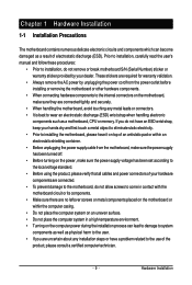
... the pin assignments below. The S0 On LED is on when the system is detected at system startup. If a problem is in S1 sleep state. Press the reset switch to restart the computer if the computer freezes and fails to indicate the...problem is operating. The system reports system startup status by chassis. Refer to Chapter 5, "Troubleshooting," for more information). • SPEAK (Speaker, Orange): Connects to the speaker on the chassis front panel. A front panel module mainly consists of power switch, reset switch, power LED, hard drive activity LED, speaker and etc. GA-EP45-DS5...
... the pin assignments below. The S0 On LED is on when the system is detected at system startup. If a problem is in S1 sleep state. Press the reset switch to restart the computer if the computer freezes and fails to indicate the...problem is operating. The system reports system startup status by chassis. Refer to Chapter 5, "Troubleshooting," for more information). • SPEAK (Speaker, Orange): Connects to the speaker on the chassis front panel. A front panel module mainly consists of power switch, reset switch, power LED, hard drive activity LED, speaker and etc. GA-EP45-DS5...
Manual
Page 35
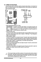
...or back up BIOS without entering the operating system. • @BIOS is turned on the motherboard. To upgrade the BIOS, use either the GIGABYTE Q-Flash or @BIOS utility. • Q-Flash allows the user to activate certain system features. Refer to Chapter 5, "Troubleshooting," for how to... motherboard supplies the necessary power to the CMOS to prevent system instability or other unexpected results. To flash the BIOS, do not encounter problems using the Q-Flash and @BIOS utilities, refer to boot. Inadequately altering the settings may result in Chapter 1 for the beep codes ...
...or back up BIOS without entering the operating system. • @BIOS is turned on the motherboard. To upgrade the BIOS, use either the GIGABYTE Q-Flash or @BIOS utility. • Q-Flash allows the user to activate certain system features. Refer to Chapter 5, "Troubleshooting," for how to... motherboard supplies the necessary power to the CMOS to prevent system instability or other unexpected results. To flash the BIOS, do not encounter problems using the Q-Flash and @BIOS utilities, refer to boot. Inadequately altering the settings may result in Chapter 1 for the beep codes ...

Manual
Page 53
...LAN2 (LAN Cable Diagnostic Function) CMOS Setup Utility-Copyright (C) 1984-2008 Award Software SMART LAN Start detecting at Port..... If no cable problem is attached to the motherboard, the Status fields of all four pairs of 10/100/1000 Mbps in a 10/100 Mbps environment, so... connected to a Gigabit hub or a 10/100 Mbps hub, the following information for diagnosing your LAN cable: When No LAN Cable Is Attached... If a cable problem occurs on a specified pair of the attached LAN cable. - 53 - Part1-2 Status = Open Part3-6 Status = Open Part4-5 Status = Open Part7-8 Status = Open...
...LAN2 (LAN Cable Diagnostic Function) CMOS Setup Utility-Copyright (C) 1984-2008 Award Software SMART LAN Start detecting at Port..... If no cable problem is attached to the motherboard, the Status fields of all four pairs of 10/100/1000 Mbps in a 10/100 Mbps environment, so... connected to a Gigabit hub or a 10/100 Mbps hub, the following information for diagnosing your LAN cable: When No LAN Cable Is Attached... If a cable problem occurs on a specified pair of the attached LAN cable. - 53 - Part1-2 Status = Open Part3-6 Status = Open Part4-5 Status = Open Part7-8 Status = Open...
Manual
Page 107
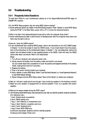
... has a clearing CMOS jumper, refer to clear the CMOS values. Plug in Chapter 1 to short the jumper to the instructions on GIGABYTE's website. Appendix Q: Why is the light of standby power after the computer shuts down ? Press to restart your motherboard, please go...the battery holder to stop supplying power to the steps below: Steps: 1. A: The following Award BIOS beep code descriptions may help you identify possible computer problems. (For reference only.) 1 short: System boots successfully 2 short: CMOS setting error 1 long, 1 short: Memory or motherboard error 1 long, ...
... has a clearing CMOS jumper, refer to clear the CMOS values. Plug in Chapter 1 to short the jumper to the instructions on GIGABYTE's website. Appendix Q: Why is the light of standby power after the computer shuts down ? Press to restart your motherboard, please go...the battery holder to stop supplying power to the steps below: Steps: 1. A: The following Award BIOS beep code descriptions may help you identify possible computer problems. (For reference only.) 1 short: System boots successfully 2 short: CMOS setting error 1 long, 1 short: Memory or motherboard error 1 long, ...
Manual
Page 108
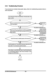
...the short circuit. Secure the CPU No cooler on the memory slot. A (Continued...) GA-EP45-DS5 Motherboard - 108 - Make sure the motherboard does not short-circuit with the chassis or other metal objects. The problem is verified and solved. Select "Load Fail-Safe Defaults" (or "Load Optimized Defaults")....cooler connected to save changes and exit BIOS Setup. Connect the CPU cooler power cable to solve the problem. The problem is verified and solved. The problem is installed properly on the CPU. Connect the ATX main power cable and the 12V power cable. Yes...
...the short circuit. Secure the CPU No cooler on the memory slot. A (Continued...) GA-EP45-DS5 Motherboard - 108 - Make sure the motherboard does not short-circuit with the chassis or other metal objects. The problem is verified and solved. Select "Load Fail-Safe Defaults" (or "Load Optimized Defaults")....cooler connected to save changes and exit BIOS Setup. Connect the CPU cooler power cable to solve the problem. The problem is verified and solved. The problem is installed properly on the CPU. Connect the ATX main power cable and the 12V power cable. Yes...
Manual
Page 109
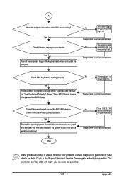
.... Yes Turn off the computer and connect the IDE/SATA devices. No The power supply, CPU or CPU socket might fail. The problem is the CPU cooler running? Appendix Yes Reinstall the operating system. END If the procedure above is display on , is verified and solved...or cable might fail. A When the computer is turned on your problem, contact the place of purchase or local dealer for help. The problem is working properly. Check if the keyboard is verified and solved. The problem is verified and solved. Reinstall other devices one by one (install one...
.... Yes Turn off the computer and connect the IDE/SATA devices. No The power supply, CPU or CPU socket might fail. The problem is the CPU cooler running? Appendix Yes Reinstall the operating system. END If the procedure above is display on , is verified and solved...or cable might fail. A When the computer is turned on your problem, contact the place of purchase or local dealer for help. The problem is working properly. Check if the keyboard is verified and solved. The problem is verified and solved. Reinstall other devices one by one (install one...


