Gigabyte GA-970A-D3 Support Question
Gigabyte GA-970A-D3 Support Question
Find answers below for this question about Gigabyte GA-970A-D3.Need a Gigabyte GA-970A-D3 manual? We have 1 online manual for this item!
Question posted by thomasv052011 on October 25th, 2012
Connecting 2-pin Power Led Line
I got a 2-pin line (Power LED) from my ATX case and the manual showed 3-pin connector. How do I do that?
Current Answers
Related Gigabyte GA-970A-D3 Manual Pages
Manual - Page 2
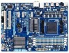
Motherboard GA-970A-D3
May 20, 2011
Motherboard GA-970A-D3
May 20, 2011
Manual - Page 4
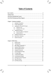
Table of Contents
Box Contents...6 Optional Items...6 GA-970A-D3 Motherboard Layout 7 GA-970A-D3 Motherboard Block Diagram 8
Chapter 1 Hardware Installation 9 1-1...Internal Connectors 21
Chapter 2 BIOS Setup 29 2-1 Startup Screen 30 2-2 The Main Menu 31 2-3 MB Intelligent Tweaker(M.I.T 33 2-4 Standard CMOS Features 39 2-5 Advanced BIOS Features 41 2-6 Integrated Peripherals 43 2-7 Power ...
Manual - Page 6
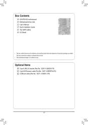
... (Part No. 12CR1-1UB030-5*R) 2-port SATA power cable (Part No. 12CF1-2SERPW-0*R) COM port cable (Part No. 12CF1-1CM001-3*R)
- 6 - Box Contents
GA-970A-D3 motherboard Motherboard driver disk User's Manual Quick Installation Guide Two SATA cables I/O Shield
• The box contents above are subject to change without notice.
• The motherboard image is for reference only and the...
Manual - Page 8
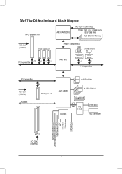
GA-970A-D3 Motherboard Block Diagram
1 PCI Express x16
AM3+/AM3 CPU
CPU CLK+/- (200 MHz) DDR3 2000 (O.C.)/1866/1600/ 1333/1066 MHz Dual Channel Memory
PCIe CLK (100 ...
14 USB 2.0/1.1
CODEC
Dual BIOS
LPC Bus iTE
IT8720
COM Port PS/2 KB/Mouse
Surround Speaker Out Center/Subwoofer Speaker Out
Side Speaker Out MIC
Line Out Line In
S/PDIF Out
2 PCI PCI CLK (33 MHz)
- 8 -
Manual - Page 9
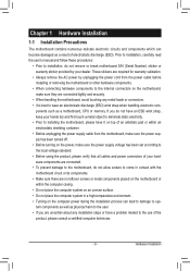
... or within an electrostatic shielding container. •• Before unplugging the power supply cable from the power outlet before installing or removing the motherboard or other hardware components.
•• When connecting hardware components to the internal connectors on the motherboard, make sure the power supply voltage has been set according to the local voltage standard. •...
Manual - Page 11
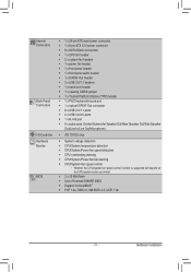
...1 x 24-pin ATX main power connector ŠŠ 1 x 8-pin ATX 12V power connector ŠŠ 6 x SATA 6Gb/s connectors ŠŠ 1 x CPU fan header ŠŠ 2 x system fan headers ŠŠ 1 x power fan header Š...Line In/Line Out/Microphone)
ŠŠ iTE IT8720 chip
ŠŠ System voltage detection ŠŠ CPU/System temperature detection ŠŠ CPU/System/Power...
Manual - Page 13
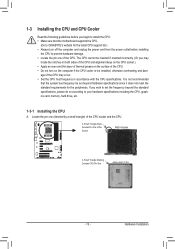
... recommended
that the motherboard supports the CPU.
(Go to GIGABYTE's website for the peripherals.
A Small Triangle Mark Denotes Pin One of the Socket
AM3+ Socket
A Small Triangle Marking Denotes CPU Pin One
AM3+/AM3...of the CPU. •• Do not turn off the computer and unplug the power cord from the power outlet before you begin to install the CPU: •• Make sure that ...
Manual - Page 14
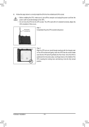
... install the CPU into the motherboard CPU socket.
•• Before installing the CPU, make sure to turn off the computer and unplug the power cord from the power outlet to prevent damage to ... lift up the CPU socket locking lever. Hardware Installation
- 14 -
Make sure that the CPU pins fit perfectly into the CPU socket. Adjust the CPU orientation if this occurs. B. Once the CPU...
Manual - Page 19
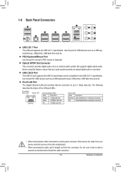
... and then remove it from the motherboard.
•• When removing the cable, pull it side to side to 1 Gbps data rate. Hardware Installation RJ-45 LAN Port The Gigabit Ethernet LAN port provides Internet connection at up to prevent an electrical short inside the cable connector.
- 19 - Use this feature, ensure that...
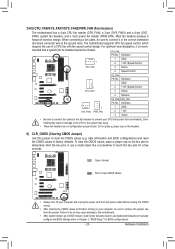
Manual - Page 21
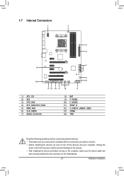
... Unplug the
power cord from the power outlet to prevent damage to the devices. •• After installing the device and before connecting external devices: •• First make sure the device cable has
been securely attached to turn off the devices and your computer. 1-7 Internal Connectors
1
3
5 2
7 8
10
11 13 14 4
12
4 6
9
1) ATX_12V 2) ATX 3) CPU_FAN...
Manual - Page 22
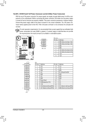
...on the motherboard. 1/2) ATX_12V/ATX (2x4 12V Power Connector and 2x12 Main Power Connector)
With the use of the power connector, the power supply can supply enough stable power to all devices are properly installed. The power connector possesses a foolproof design. The 12V power connector mainly supplies power to the power connector in the correct orientation. Connect the power supply cable...
Manual - Page 23
... headers, and a 3-pin power fan header (PWR_FAN). Most fan headers possess a
foolproof insertion design. For optimum heat dissipation, it in damage to the CPU or the system may cause damage to the motherboard.
•• After system restart, go to BIOS Setup to load factory defaults (select Load Optimized Defaults) or manually configure the...
Manual - Page 25
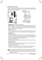
... the chassis front panel. When connecting your system using the power switch (refer to Chapter 2, "BIOS Setup," "Power Management Setup," for information about beep codes.
•• HD (Hard Drive Activity LED, Blue) Connects to the chassis intrusion switch/sensor on the chassis front panel. Note the positive and negative pins before connecting the cables. PW+ PWSPEAK...
Manual - Page 26
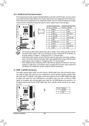
...module that has separated connectors on both of the motherboard header. Make sure the wire assignments of the module connector match the pin assignments of the front and back panel audio connections simultane- Definition
9
1
1 MIC2_L
F_PANEL(NH)
2 GND
Pin No. 1 2
Definition MIC GND
F_PANEL (H61M-D2)
10
2
3 MIC2_R 4 -ACZ_DET
3 MIC Power 4 NC
5 LINE2_R
5 Line Out (R)
6 GND
6 NC...
Manual - Page 28
DB_PORT
BIOS S
1
1
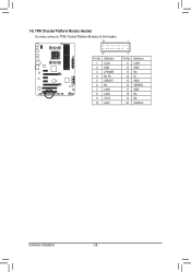
14) TPM (Trusted Platform Module Header) You may connect a TPM (Trusted Platform Module) to this header.
19 TPM w/housing
20
Pin No. Definition
11 LAD0
1
12 GND PCIe power connector (SATA)(X58A-OC)
13 NC
14 ID
15 SB3V
16 SERIRQ
17 GND
18 NC
19 NC
20 SUSCLK
Hardware Installation
- 28 - Definition...
Manual - Page 49
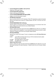
...to the CPU temperature. Current CPU/SYSTEM/POWER FAN Speed (RPM)
Displays current CPU/system/power fan speed. Check the fan condition or fan connection when this occurs. (Default: Disabled) ... warning threshold for a 3-pin CPU fan. PWM Sets PWM mode for a 4-pin CPU fan. BIOS Setup This item is configurable only when CPU Smart FAN Control is not connected or fails. Enabled allows ...
Manual - Page 63
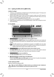
... Updating the BIOS Restart your system after the system restarts. Make sure that matches your motherboard model. Unique Features Failure to do NOT interrupt the
Internet connection (for your motherboard is not present on the @BIOS server site, please
manually download the BIOS update file from GIGABYTE Server, select the @BIOS server site closest...
Manual - Page 69
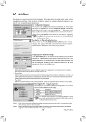
... Green re-detect the device.)
Before creating a Bluetooth cell phone key, make sure it to connect to 30 seconds in 5-second increment.
The Configuration dialog box: First, you can set . ...Suspend to RAM mode without the need to press the power button first.
(Note 1) (Note 2)
If your phone. When the phone is in the motherboard package(Note 2) allows you to wake up the system...
Manual - Page 70
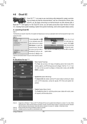
... to the
Cloud OC server. Available functions may differ by motherboard model.
Bluetooth PAN (Personal Area Network) support is normal.
Click the or but- ton under an item you can system status. By simply connecting to an Internet browser via virtually any Internet-connected device, such as CPU temperature, cooling fan speeds, CPU...
Manual - Page 88
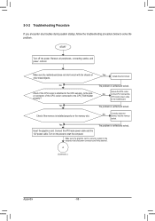
...Connect the ATX main power cable and the 12V power cable.
Remove all peripherals, connecting cables, and power cord etc. Secure the CPU cooler
No
on the power to start the computer. Yes
The problem is verified and solved.
Make sure the motherboard...on the CPU. Is the power connector of the CPU cooler connected to the motherboard. START
Turn off the power. No
Correctly insert the ...
Similar Questions

How Do I Connect 3 Monitors To B75m-hd3 Motherboard
1 monitor connected to on board graphics port, 2 monitors connected to graphics card
1 monitor connected to on board graphics port, 2 monitors connected to graphics card
(Posted by stageskills 9 years ago)


How To Manually Overclock Gigabyte Motherboard Ga-970a-ud3
(Posted by mk45Snowfl 9 years ago)


Sleep Mode
I can't get my computer to sleep.When I try it sleeps for about 5 secends then powers up.Also if I l...
I can't get my computer to sleep.When I try it sleeps for about 5 secends then powers up.Also if I l...
(Posted by kgrinstall 11 years ago)