
Owner's Manual
Page 6
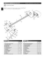
... Rail Section 3B Middle Rail Section 3C End Rail Section 4 1/4-20 Hex Hd Shoulder Bolt 5 1/4"-20 Hex Flange Nut 6 Carriage Stop 7 Rail Clamps 8 5/16" Hex Shoulder Bolt 9 5/16" Hex Flange Nut 10 Carriage Assembly 11 Collar 12 Retaining Clip 13 Rail Strap 15A Open Limit Switch Assembly (Grey) Parts Required 1 Piece 3-Piece...
... Rail Section 3B Middle Rail Section 3C End Rail Section 4 1/4-20 Hex Hd Shoulder Bolt 5 1/4"-20 Hex Flange Nut 6 Carriage Stop 7 Rail Clamps 8 5/16" Hex Shoulder Bolt 9 5/16" Hex Flange Nut 10 Carriage Assembly 11 Collar 12 Retaining Clip 13 Rail Strap 15A Open Limit Switch Assembly (Grey) Parts Required 1 Piece 3-Piece...
Owner's Manual
Page 8
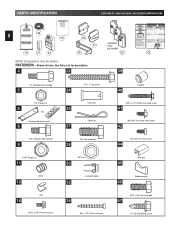
... vary by model 38 50 43 NOTE: Accessories vary by model. FASTENERS - See Parts List for description. 4 22 39 1/4" Shoulder bolt w/flange 5 1/4" Flange nut 6 OR Carriage stop (not to scale) 8 5/16" Shoulder bolt w/flange 9 5/16" Flange nut 11 Collar 12 Clip 16 #8-32 x 3/8" Hex head screw 24 1/4" x 2" Lag screw Clevis pin...
... vary by model 38 50 43 NOTE: Accessories vary by model. FASTENERS - See Parts List for description. 4 22 39 1/4" Shoulder bolt w/flange 5 1/4" Flange nut 6 OR Carriage stop (not to scale) 8 5/16" Shoulder bolt w/flange 9 5/16" Flange nut 11 Collar 12 Clip 16 #8-32 x 3/8" Hex head screw 24 1/4" x 2" Lag screw Clevis pin...

Owner's Manual
Page 10
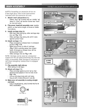
....354.3643 OR GENIECOMPANY.COM bumper coupler serial no longer turn freely. Fig. 1-1. 3. Set power head on its bottom. NOTE: If you have this type Carriage Stop, skip Step 2. Fig. 1-4. Fig. 1-5. • For 1-piece rail, skip to power head. • (3-piece only)Select "first" rail section. (It has protective cardboard sleeve...
....354.3643 OR GENIECOMPANY.COM bumper coupler serial no longer turn freely. Fig. 1-1. 3. Set power head on its bottom. NOTE: If you have this type Carriage Stop, skip Step 2. Fig. 1-4. Fig. 1-5. • For 1-piece rail, skip to power head. • (3-piece only)Select "first" rail section. (It has protective cardboard sleeve...
Owner's Manual
Page 13
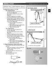
... head 11. Fig. 1-15 correct [9] 5/16" Flange nut rail strap [46] 5/16" x 3/4" Hex head bolt Fig. 1-16 wrong Install carriage [10]. • Place emergency release lever in engaged position. MAIN ASSEMBLY FOR HELP-1.800.354.3643 OR GENIECOMPANY.COM NOTE: If installing an extension kit...assembly. Fig. 1-14. • Make sure arrow on side of rail. carriage arrow engaged released NOTE: Carriage can be facing power head.) • Slide carriage into rail. Slide carriage to the instructions carriage stop along rail until it rests against end of rail so that entire length of...
... head 11. Fig. 1-15 correct [9] 5/16" Flange nut rail strap [46] 5/16" x 3/4" Hex head bolt Fig. 1-16 wrong Install carriage [10]. • Place emergency release lever in engaged position. MAIN ASSEMBLY FOR HELP-1.800.354.3643 OR GENIECOMPANY.COM NOTE: If installing an extension kit...assembly. Fig. 1-14. • Make sure arrow on side of rail. carriage arrow engaged released NOTE: Carriage can be facing power head.) • Slide carriage into rail. Slide carriage to the instructions carriage stop along rail until it rests against end of rail so that entire length of...

Owner's Manual
Page 14
... wire clip [44] to temporarily hold switch in top of rail about 12 inches from power head. Fig. 1-17. - Check that white lever is on carriage). - Insert set screw [16] into limit switch hand tight only to help maintain slack. Please set screw A brown wire wire clip Fig. 1-20 "open" switch...
... wire clip [44] to temporarily hold switch in top of rail about 12 inches from power head. Fig. 1-17. - Check that white lever is on carriage). - Insert set screw [16] into limit switch hand tight only to help maintain slack. Please set screw A brown wire wire clip Fig. 1-20 "open" switch...
Owner's Manual
Page 21
... Fig. 2-14 [27] 3/8" Hex head bolt [28] 3/8" Nut Fig. 2-14. - Overall length of arms together should be as long as possible. Move carriage as possible, but must be easily reached. • Pull cord through lever until knob is fully closed. Place bolts [27] and nuts [28] as far... as necessary to adjust length. Fig. 2-14. - Fig. 2-14. - Fig. 2-14. a. Tighten bolts and nuts. • For 1-piece doors. - Move carriage as necessary to carriage. Connect short leg of curved arm to clear vehicles yet maintain height where it can be 21 some angle off excess cord. Use clevis...
... Fig. 2-14 [27] 3/8" Hex head bolt [28] 3/8" Nut Fig. 2-14. - Overall length of arms together should be as long as possible. Move carriage as possible, but must be easily reached. • Pull cord through lever until knob is fully closed. Place bolts [27] and nuts [28] as far... as necessary to adjust length. Fig. 2-14. - Fig. 2-14. - Fig. 2-14. a. Tighten bolts and nuts. • For 1-piece doors. - Move carriage as necessary to carriage. Connect short leg of curved arm to clear vehicles yet maintain height where it can be 21 some angle off excess cord. Use clevis...
Owner's Manual
Page 25
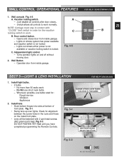
... the metal front plate. • Lens will be fastened with 2 pan head screws. ([42] green parts bag). Unlock allows all controls after door closes.. - NOTE: Carriage must stay in contact with "CLOSE" limit switch in order for alignment between the screw holes in front plate Fig. 5-1 pan head screws secure top...
... the metal front plate. • Lens will be fastened with 2 pan head screws. ([42] green parts bag). Unlock allows all controls after door closes.. - NOTE: Carriage must stay in contact with "CLOSE" limit switch in order for alignment between the screw holes in front plate Fig. 5-1 pan head screws secure top...
Owner's Manual
Page 27
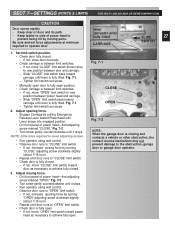
...switch position. • Check door fully closed . 3. If not, move "CLOSE" limit switch (brown wire) to new position between power head and carriage. - If not, move "OPEN" limit switch toward power head as necessary to achieve fully closed . - Fig. 7-2. • Turn screw gently ...7-2 NOTE: When the garage door is fully lifted. If not, close door manually. • Check carriage is between limit switches. - NOTE: Little force required to move "CLOSE" limit switch toward carriage until door runs to "CLOSE" limit switch. • Check door is fully lifted. lever (actuator ...
...switch position. • Check door fully closed . 3. If not, move "CLOSE" limit switch (brown wire) to new position between power head and carriage. - If not, move "OPEN" limit switch toward power head as necessary to achieve fully closed . - Fig. 7-2. • Turn screw gently ...7-2 NOTE: When the garage door is fully lifted. If not, close door manually. • Check carriage is between limit switches. - NOTE: Little force required to move "CLOSE" limit switch toward carriage until door runs to "CLOSE" limit switch. • Check door is fully lifted. lever (actuator ...
Owner's Manual
Page 31
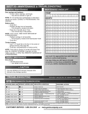
...THE DOOR CAN BE CLOSED IF YOU: 1. MONTH 31 J J JJJ JJJJJ J JJJJJ JJJJ Balance door. • Close door. • Release carriage from rail assembly. - Drive Screw • Lubricate drive screw. - DISCONNECT THE STB SYSTEM FROM THE OPERATOR AND 2. Door should stay in the ... MMMM A A AAA AAAAA A AAAAA AAAA M M MMM MMMMM M MMMMM MMMM NOTE: If door moves, HAVE DOOR SERVICED BY A PROFESSIONAL. • Reattach carriage to rail assembly. - See page 28, CONTACT REVERSE. Use GENIE GLU3 lubricant. CAUTION Use only GENIE GLU3 lubricant, because other lubricants may damage operator.
...THE DOOR CAN BE CLOSED IF YOU: 1. MONTH 31 J J JJJ JJJJJ J JJJJJ JJJJ Balance door. • Close door. • Release carriage from rail assembly. - Drive Screw • Lubricate drive screw. - DISCONNECT THE STB SYSTEM FROM THE OPERATOR AND 2. Door should stay in the ... MMMM A A AAA AAAAA A AAAAA AAAA M M MMM MMMMM M MMMMM MMMM NOTE: If door moves, HAVE DOOR SERVICED BY A PROFESSIONAL. • Reattach carriage to rail assembly. - See page 28, CONTACT REVERSE. Use GENIE GLU3 lubricant. CAUTION Use only GENIE GLU3 lubricant, because other lubricants may damage operator.
Owner's Manual
Page 32
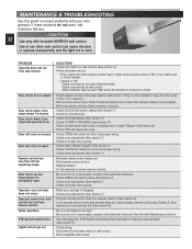
... reason. Check force adjustment (See Section 7). Be sure door is cut into receiver memory (See section 9). Check OPEN limit switch setting (See section 7). Make sure carriage is OK. Be sure door is OK: - Disconnect & reconnect wires on wall console (See section 4). Remote control has less than 25 feet operating range. Motor...
... reason. Check force adjustment (See Section 7). Be sure door is cut into receiver memory (See section 9). Check OPEN limit switch setting (See section 7). Make sure carriage is OK. Be sure door is OK: - Disconnect & reconnect wires on wall console (See section 4). Remote control has less than 25 feet operating range. Motor...


