

Owner's Manual
Page 10
...Secure "first" rail section with shaft. (It will no . 2. Fig. 1-1. Set power head so that front panel (with end of screw against coupler. CAUTION Drive screws can slide out of bumper. • Stick bumper into rail attachment flange until holes in rail match up to step 8. [39] Coupler... [45] Rubber bumper Fig. 1-1 Fig. 1-2 Fig. 1-3 Fig. 1-4 Fig. 1-4. • Turn screw until it engages with coupler. • Slide rail...
...Secure "first" rail section with shaft. (It will no . 2. Fig. 1-1. Set power head so that front panel (with end of screw against coupler. CAUTION Drive screws can slide out of bumper. • Stick bumper into rail attachment flange until holes in rail match up to step 8. [39] Coupler... [45] Rubber bumper Fig. 1-1 Fig. 1-2 Fig. 1-3 Fig. 1-4 Fig. 1-4. • Turn screw until it engages with coupler. • Slide rail...

Owner's Manual
Page 24
... can cause the door to operate unexpectedly and the light not to work. • Cut or pinched wires can cause door operator to malfunction. Tighten screws • Connect wires to wall control. - Fig. 4-4. • Remove protective backing. • Stick label to wall next to wall control - Fig. 4-2, Fig. 4-3..... CAUTION • Use of door and away from wall control to power head. • Use staples to fasten wire to hold wire. 1. Drive staples just tight enough to ceiling and wall. At least 5 feet from floor, so small children cannot reach it. • Route wire from...
... can cause the door to operate unexpectedly and the light not to work. • Cut or pinched wires can cause door operator to malfunction. Tighten screws • Connect wires to wall control. - Fig. 4-4. • Remove protective backing. • Stick label to wall next to wall control - Fig. 4-2, Fig. 4-3..... CAUTION • Use of door and away from wall control to power head. • Use staples to fasten wire to hold wire. 1. Drive staples just tight enough to ceiling and wall. At least 5 feet from floor, so small children cannot reach it. • Route wire from...
Owner's Manual
Page 31
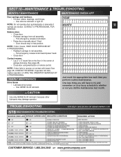
...carriage from rail assembly. - See page 28, CONTACT REVERSE. DISCONNECT THE STB SYSTEM FROM THE OPERATOR AND 2. CONTACT A PROFESSIONAL FOR SERVICE. Drive Screw • Lubricate drive screw. - BEAM OBSTRUCTED 3.SENSOR DEFECTIVE 1.CHECK ALIGNMENT 2. F F FFF FFFFF F FFFFF FFFF M M MMM MMMMM M MMMMM MMMM A A... JJJJJ JJJJ A A AAA AAAAA A AAAAA AAAA Contact reverse. • Lay 2" x 4" board flat on contact with board. Use GENIE GLU3 lubricant. CHECK FOR OBSTRUCTION 3.CALL CUSTOMER SERVICE 2 BLINKS, PAUSE (REPEAT) OFF 1.WIRE TO SENSOR MISSING OR BAD 2.SENSOR DEFECTIVE 1....
...carriage from rail assembly. - See page 28, CONTACT REVERSE. DISCONNECT THE STB SYSTEM FROM THE OPERATOR AND 2. CONTACT A PROFESSIONAL FOR SERVICE. Drive Screw • Lubricate drive screw. - BEAM OBSTRUCTED 3.SENSOR DEFECTIVE 1.CHECK ALIGNMENT 2. F F FFF FFFFF F FFFFF FFFF M M MMM MMMMM M MMMMM MMMM A A... JJJJJ JJJJ A A AAA AAAAA A AAAAA AAAA Contact reverse. • Lay 2" x 4" board flat on contact with board. Use GENIE GLU3 lubricant. CHECK FOR OBSTRUCTION 3.CALL CUSTOMER SERVICE 2 BLINKS, PAUSE (REPEAT) OFF 1.WIRE TO SENSOR MISSING OR BAD 2.SENSOR DEFECTIVE 1....


