

Owner's Manual
Page 1
.... . . . 23 23 8 FINE LIMIT SWITCH ADJUSTMENTS 24 9 REMOTE CONTROLS 24-25 10 BATTERY & VISOR CLIP INSTALLATION 25 11 LIGHT BULB AND LENS INSTALLATION 26 MAINTENANCE 27 TROUBLESHOOTING GUIDE 28 WIRING DIAGRAM 29 ACCESSORIES 30 WARRANTY 32 Self-diagnostic Electronic Sensory Protection System (SAFE-T-BEAM SYSTEM) MUST Be Installed To Close Door! 3507535556 GPS-IC Series PMX-IC B Series Automatic Chain Drive/Belt Drive Garage Door Operator System Complete with and SERIES II Electronics Remote Control Operator MUST be installed with the included SERIES II Wall Control!
.... . . . 23 23 8 FINE LIMIT SWITCH ADJUSTMENTS 24 9 REMOTE CONTROLS 24-25 10 BATTERY & VISOR CLIP INSTALLATION 25 11 LIGHT BULB AND LENS INSTALLATION 26 MAINTENANCE 27 TROUBLESHOOTING GUIDE 28 WIRING DIAGRAM 29 ACCESSORIES 30 WARRANTY 32 Self-diagnostic Electronic Sensory Protection System (SAFE-T-BEAM SYSTEM) MUST Be Installed To Close Door! 3507535556 GPS-IC Series PMX-IC B Series Automatic Chain Drive/Belt Drive Garage Door Operator System Complete with and SERIES II Electronics Remote Control Operator MUST be installed with the included SERIES II Wall Control!
Owner's Manual
Page 2
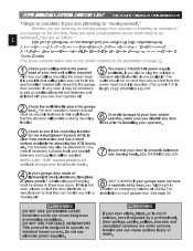
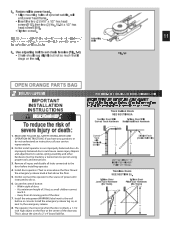
... can furnish you with a "bracing kit " 8 (NOT SHOWN) If your operator. 3 Check to see if the mounting location for the Safe-T-Beam® System (STB) is possible that your new door operator kit) Check the wall directly above the garage 2 door. They are planning to consider an emergency release kit (GER-2) for attaching the STB brackets. If you plan to plug the unit into a Plan how you might want...
... can furnish you with a "bracing kit " 8 (NOT SHOWN) If your operator. 3 Check to see if the mounting location for the Safe-T-Beam® System (STB) is possible that your new door operator kit) Check the wall directly above the garage 2 door. They are planning to consider an emergency release kit (GER-2) for attaching the STB brackets. If you plan to plug the unit into a Plan how you might want...
Owner's Manual
Page 4
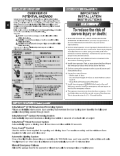
... seconds Force Guard® Control Used to set the force required for opening and closing door For maximum safety set the minimum force required to fully open position if anything passes through beam Safe-T-Reverse® Contact Reversing System Automatically stops and reverses a closing door if door does not close door Automatic Lighting System One or two light bulbs (depending on model) up to cables, spring assembly, and other hardware must be opened or closed manually for safer entries and exits The light turns on...
... seconds Force Guard® Control Used to set the force required for opening and closing door For maximum safety set the minimum force required to fully open position if anything passes through beam Safe-T-Reverse® Contact Reversing System Automatically stops and reverses a closing door if door does not close door Automatic Lighting System One or two light bulbs (depending on model) up to cables, spring assembly, and other hardware must be opened or closed manually for safer entries and exits The light turns on...
Owner's Manual
Page 6
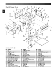
... Tap 13 Light Socket (by series/model) Item Part Name 21 Rectifier Board Assembly 22 Fuse (F1), UL 23 Fuse (F2), UL 24 Limit Gear Shroud 25 Motor Bracket 26 Screw, #10 x 3/8" HH 27 Limit Plate/Pin Assembly 28 Limit Switch 29 Screw,#4 40 x 5/8"Slot HH w/Wshr,SfTap 30 Motor Assembly 31 Motor Adapter Plate 32 Screw, 1/4"-20 x 1/2" Slt HH w/Wshr 33 Limit Worm Gear 34 Limit Gear Bushing 35 Limit Worm Drive 36 Limit Worm Shim 37 Limit Wheel 38...
... Tap 13 Light Socket (by series/model) Item Part Name 21 Rectifier Board Assembly 22 Fuse (F1), UL 23 Fuse (F2), UL 24 Limit Gear Shroud 25 Motor Bracket 26 Screw, #10 x 3/8" HH 27 Limit Plate/Pin Assembly 28 Limit Switch 29 Screw,#4 40 x 5/8"Slot HH w/Wshr,SfTap 30 Motor Assembly 31 Motor Adapter Plate 32 Screw, 1/4"-20 x 1/2" Slt HH w/Wshr 33 Limit Worm Gear 34 Limit Gear Bushing 35 Limit Worm Drive 36 Limit Worm Shim 37 Limit Wheel 38...
Owner's Manual
Page 8
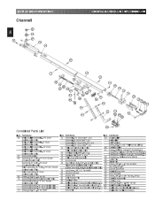
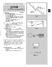
Release Cord-7'6" Doors(26.5") Emergency Release Cord 8' & 10' Doors(56.5") Emergency Release Cord -12' Doors(96.0") Emergency Release Knob (Red) Cotter Pin Clevis Pin Screw, 3/8"-16 x .87 Hx Hd Mch Hex Nut, 3/8"-16 Curved Door Arm Straight Door Arm Door Bracket Screw, 1/4"-20 x 3/4" Hx Hd, Sf Tap Carriage Assembly Carriage Cap Screw, #10-14 x 1-5/16" Hx Hd Wall Console (Series II ) Roller Chain -10' Door (Chain Only)(328.5") 101 Wall Button (Series II ) (lit primary) 71 Screw, #10-24 x .38 Hx Hd/W 8mm Belt Wall Button (unlit secondary) PARTS IDENTIFICATION...
Release Cord-7'6" Doors(26.5") Emergency Release Cord 8' & 10' Doors(56.5") Emergency Release Cord -12' Doors(96.0") Emergency Release Knob (Red) Cotter Pin Clevis Pin Screw, 3/8"-16 x .87 Hx Hd Mch Hex Nut, 3/8"-16 Curved Door Arm Straight Door Arm Door Bracket Screw, 1/4"-20 x 3/4" Hx Hd, Sf Tap Carriage Assembly Carriage Cap Screw, #10-14 x 1-5/16" Hx Hd Wall Console (Series II ) Roller Chain -10' Door (Chain Only)(328.5") 101 Wall Button (Series II ) (lit primary) 71 Screw, #10-24 x .38 Hx Hd/W 8mm Belt Wall Button (unlit secondary) PARTS IDENTIFICATION...

Owner's Manual
Page 10
Attach emergency release tag (Fig. 1-1). • Thread wire through knob so knot is mounted. 2. Slide drive end of channel down over "D"-shaft on top of power head (Fig.1-2). • Support header end of rail level with power head. • Slide carriage enough to align "D"-shaft with "D"-hole in sprocket. • Slide rail down "D"-shaft flush with power head. 5. Place power head and rail on the rail FOR HELP-1.800.354...
Attach emergency release tag (Fig. 1-1). • Thread wire through knob so knot is mounted. 2. Slide drive end of channel down over "D"-shaft on top of power head (Fig.1-2). • Support header end of rail level with power head. • Slide carriage enough to align "D"-shaft with "D"-hole in sprocket. • Slide rail down "D"-shaft flush with power head. 5. Place power head and rail on the rail FOR HELP-1.800.354...
Owner's Manual
Page 11
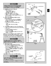
... service person using proper tools and instructions. 3. Repairs and adjustments to set chain tension (Fig. 1-4) • Cdrhaagisnosnhothueldrsaail.g slightly but not so much that it . • Away from all locks connected to the wall button or console. Do Not connect the operator to power head. • • • ThsIAanicneglsirdagheedntwrpetonmsstcw[h1osreeec1urrw2tnewh]tsw,ieont[sagh6(.d2e9h)n]fo.r5altew/m1so6eo"(.f2xs)1pN/r2oo"c. Fasten rail to the source of a 2" x 4" board laid...
... service person using proper tools and instructions. 3. Repairs and adjustments to set chain tension (Fig. 1-4) • Cdrhaagisnosnhothueldrsaail.g slightly but not so much that it . • Away from all locks connected to the wall button or console. Do Not connect the operator to power head. • • • ThsIAanicneglsirdagheedntwrpetonmsstcw[h1osreeec1urrw2tnewh]tsw,ieont[sagh6(.d2e9h)n]fo.r5altew/m1so6eo"(.f2xs)1pN/r2oo"c. Fasten rail to the source of a 2" x 4" board laid...
Owner's Manual
Page 13
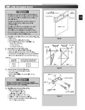
... for mounting are not included. • After power head is on line "H." • Mark hole positions "A" and "B." • Drill 5/32" holes at marked positions. • Flaagstsecnrebwrasc[k7e9t].to header using two (2) 1/4" x 2" CVoefenrDtetiorcloainrle Lag Screws [79] 4. CAUTION Header bracket must be fastened to garage fbroaamrdin,gp.laDsoteNrootrfaosthteenr stoucdhrymwaatlel,rpiaalsrt.icle Line "V" "B" "A" Header Bracket 3. center hole is installed, remove supporting material. • Close door. 7. Spring...
... for mounting are not included. • After power head is on line "H." • Mark hole positions "A" and "B." • Drill 5/32" holes at marked positions. • Flaagstsecnrebwrasc[k7e9t].to header using two (2) 1/4" x 2" CVoefenrDtetiorcloainrle Lag Screws [79] 4. CAUTION Header bracket must be fastened to garage fbroaamrdin,gp.laDsoteNrootrfaosthteenr stoucdhrymwaatlel,rpiaalsrt.icle Line "V" "B" "A" Header Bracket 3. center hole is installed, remove supporting material. • Close door. 7. Spring...
Owner's Manual
Page 14
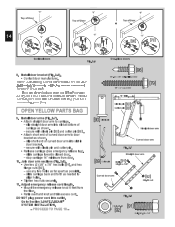
... closed door. 14" minimum from • Retie overhand knot and trim excess cord. Install door bracket (Fig. 2-6). • Contact door manufacturer. dsloiporsbhroarctkeent.d of Door OR 14 "V" [96] [79] "V" [96] [79] "V" [96] [79] Sectional doors Fig. 2-6 One-piece doors 8. Install door arms (Fig. 2-7). • Attach straight door arm to door bracket as shown. - slip straight door arm into outlet. DO NOT plug power cord into slot at bottom of curved door arm to carriage. - Adjust emergency release...
... closed door. 14" minimum from • Retie overhand knot and trim excess cord. Install door bracket (Fig. 2-6). • Contact door manufacturer. dsloiporsbhroarctkeent.d of Door OR 14 "V" [96] [79] "V" [96] [79] "V" [96] [79] Sectional doors Fig. 2-6 One-piece doors 8. Install door arms (Fig. 2-7). • Attach straight door arm to door bracket as shown. - slip straight door arm into outlet. DO NOT plug power cord into slot at bottom of curved door arm to carriage. - Adjust emergency release...
Owner's Manual
Page 15
... centerline Fig. 2-11 Lag screws [79] up header about 6." - Locate header bracket (Fig. 2-9). • Use TABLE A to draw vertical line "V." - center hole is the door rise in inches Locate header bracket above top edge of door and header (Fig. 2-9). • Close door. • Measure door width. 2B... FOR TRACKLESS DOORS WARNING • Do Not try to remove, repair or adjust springs or anything to 20" 3. Establish...
... centerline Fig. 2-11 Lag screws [79] up header about 6." - Locate header bracket (Fig. 2-9). • Use TABLE A to draw vertical line "V." - center hole is the door rise in inches Locate header bracket above top edge of door and header (Fig. 2-9). • Close door. • Measure door width. 2B... FOR TRACKLESS DOORS WARNING • Do Not try to remove, repair or adjust springs or anything to 20" 3. Establish...
Owner's Manual
Page 17
... door arm to carriage. - slip curved door arm into slot in carriage. - Mount po TERNATE [92] 3/8-16 nut 17 MOUNTING METHODS). • Be sure rail assembly and power head are not included. • After power head is installed, remove supporting material. • Close door. 10. slip straight door arm into slot in door bracket. - secure with clevis pin [90] and cotter pin [89]. • Release carriage (See emergency release tag). • Slide carriage toward door. • Attach short end of assembled door arms...
... door arm to carriage. - slip curved door arm into slot in carriage. - Mount po TERNATE [92] 3/8-16 nut 17 MOUNTING METHODS). • Be sure rail assembly and power head are not included. • After power head is installed, remove supporting material. • Close door. 10. slip straight door arm into slot in door bracket. - secure with clevis pin [90] and cotter pin [89]. • Release carriage (See emergency release tag). • Slide carriage toward door. • Attach short end of assembled door arms...
Owner's Manual
Page 19
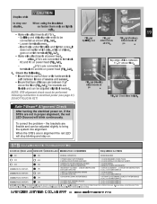
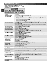
... SELF-DIAGNOSTIC TROUBLESHOOTING SOURCE (RED LED) SENSOR (GREEN LED) INDICATED CONDITION REQUIRED ACTION ON ON NORMAL OPERATION NONE REQUIRED OFF OFF 1.POWER HEAD NOT POWERED 2.WIRING FROM POWER HEAD BAD 1.CHECK BREAKERS, FUSES, PLUGS 2.CHECK WIRING FOR OBVIOUS SHORTS OFF ON 1.WIRING TO SOURCE MISSING OR BAD 2.POWER HAS BEEN INTERRUPTED 1.CHECK WIRING 2.REMOVE POWER AND REAPPLY 2 BLINKS, PAUSE (REPEAT) ON 1.BEAM NOT ALIGNED 2. CHECK FOR OBSTRUCTION 3.CALL CUSTOMER SERVICE 2 BLINKS, PAUSE (REPEAT) OFF 1.WIRE TO SENSOR...
... SELF-DIAGNOSTIC TROUBLESHOOTING SOURCE (RED LED) SENSOR (GREEN LED) INDICATED CONDITION REQUIRED ACTION ON ON NORMAL OPERATION NONE REQUIRED OFF OFF 1.POWER HEAD NOT POWERED 2.WIRING FROM POWER HEAD BAD 1.CHECK BREAKERS, FUSES, PLUGS 2.CHECK WIRING FOR OBVIOUS SHORTS OFF ON 1.WIRING TO SOURCE MISSING OR BAD 2.POWER HAS BEEN INTERRUPTED 1.CHECK WIRING 2.REMOVE POWER AND REAPPLY 2 BLINKS, PAUSE (REPEAT) ON 1.BEAM NOT ALIGNED 2. CHECK FOR OBSTRUCTION 3.CALL CUSTOMER SERVICE 2 BLINKS, PAUSE (REPEAT) OFF 1.WIRE TO SENSOR...
Owner's Manual
Page 20
... wall control. - Mount wall control (Fig. 4-2). • Use two pan head screws. 5. • Remove protective backing and stick near wall control. • Use tacks or staples to work normally Independent Light Control - Connect striped wires to terminal "2" on power head and "B" on wall control. - LOCK disables controls after door activation NOTE: Additional wall controls are available from 3 inside garage 4 - UNLOCK allows controls to permanently mount Label. • Make sure everyone reads and follows WARNINGS. Goes out when Security Lock Switch...
... wall control. - Mount wall control (Fig. 4-2). • Use two pan head screws. 5. • Remove protective backing and stick near wall control. • Use tacks or staples to work normally Independent Light Control - Connect striped wires to terminal "2" on power head and "B" on wall control. - LOCK disables controls after door activation NOTE: Additional wall controls are available from 3 inside garage 4 - UNLOCK allows controls to permanently mount Label. • Make sure everyone reads and follows WARNINGS. Goes out when Security Lock Switch...
Owner's Manual
Page 21
... PERMANENT WIRING INSTRUCTIONS FOR ELECTRICIAN 1. Remove existing power cord from the branch 2. CONNECT OPERATOR TO POWER FOR HELP-1.800.354.3643 OR GENIECOMPANY.COM WARNING To reduce the risk of 6 inches. 5. Install permanent wiring to be properly grounded to prevent personal injury and damage to green wire location (GROUND). Fig. 5-1 ing electrical connections. 1. Replace power head bottom cover. • Replace and tighten four (4) hex head screws. Check local building codes...
... PERMANENT WIRING INSTRUCTIONS FOR ELECTRICIAN 1. Remove existing power cord from the branch 2. CONNECT OPERATOR TO POWER FOR HELP-1.800.354.3643 OR GENIECOMPANY.COM WARNING To reduce the risk of 6 inches. 5. Install permanent wiring to be properly grounded to prevent personal injury and damage to green wire location (GROUND). Fig. 5-1 ing electrical connections. 1. Replace power head bottom cover. • Replace and tighten four (4) hex head screws. Check local building codes...
Owner's Manual
Page 22
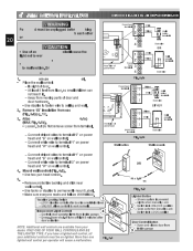
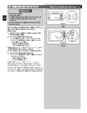
6... Before starting main limit switch settings, LOCK carriage onto rail assembly (See emergency release tag). 1. Set "OPEN" limit switch (Fig 6-1). • Locate limit set switch on back of power head. • Push and hold limit set . release the limit set switch until door moves to operate door. Set "CLOSE" limit switch (Fig. 6-1). • Push and hold limit set switch. - FOR HELP-1.800.354.3643 OR GENIECOMPANY.COM O EN COE 1 2 NEC CLASS 2 3 4 MORE MORE CLO E O EN L MIT ADJUSTMENT PUSH TO SET LIM TS PUSH TO SET LIMITSC STEALTH ORSE ONLY IE II CO NOTE...
6... Before starting main limit switch settings, LOCK carriage onto rail assembly (See emergency release tag). 1. Set "OPEN" limit switch (Fig 6-1). • Locate limit set switch on back of power head. • Push and hold limit set . release the limit set switch until door moves to operate door. Set "CLOSE" limit switch (Fig. 6-1). • Push and hold limit set switch. - FOR HELP-1.800.354.3643 OR GENIECOMPANY.COM O EN COE 1 2 NEC CLASS 2 3 4 MORE MORE CLO E O EN L MIT ADJUSTMENT PUSH TO SET LIM TS PUSH TO SET LIMITSC STEALTH ORSE ONLY IE II CO NOTE...
Owner's Manual
Page 23
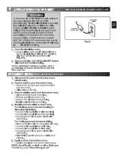
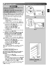
...; Locate screw on back of power head marked "CLOSE FORCE." • Gently turn screw counterclockwMisOeR until it switch and "CLOSE FORCE" adjustment until it stops. NOTE: Little effort is required to reset. NOTE: Set minimum force required to open . FOR HELP-1.800.354.3643 OR GENIECOMPANY.COM STEALTH OP N CL SE OR LIMIT SET OPEN FORCE CLOSE FORCE RADIO SIGNAL LEARN CODE PRO MAX MORE FORCE Fig. 7-1 1 2 NEC CLASS 2 3 4 MO E MORE C OSE OPEN L MIT ADJUSTMENT PUSH TO SET LIM TS NOTE USE O LY...
...; Locate screw on back of power head marked "CLOSE FORCE." • Gently turn screw counterclockwMisOeR until it switch and "CLOSE FORCE" adjustment until it stops. NOTE: Little effort is required to reset. NOTE: Set minimum force required to open . FOR HELP-1.800.354.3643 OR GENIECOMPANY.COM STEALTH OP N CL SE OR LIMIT SET OPEN FORCE CLOSE FORCE RADIO SIGNAL LEARN CODE PRO MAX MORE FORCE Fig. 7-1 1 2 NEC CLASS 2 3 4 MO E MORE C OSE OPEN L MIT ADJUSTMENT PUSH TO SET LIM TS NOTE USE O LY...
Owner's Manual
Page 24
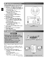
... may open position by pushing wall control. • Locate curved "CLOSE" limit adjustment slot on back of opening Do Not allow children to close 6. clockwise to reset. 1. Wait about 20 minutes for pinion screw. • Insert a screwdriver and turn pinion screw. - If safety reverse does not work if STB's malfunction Winchheensparwogaryamfromminagnrteemnnoat.e control keep at least 24 1. Repeat step as necessary to door and door operator owner's Manuals before attempting any repairs NcoOnTtrEo:l.Factory sets different codes...
... may open position by pushing wall control. • Locate curved "CLOSE" limit adjustment slot on back of opening Do Not allow children to close 6. clockwise to reset. 1. Wait about 20 minutes for pinion screw. • Insert a screwdriver and turn pinion screw. - If safety reverse does not work if STB's malfunction Winchheensparwogaryamfromminagnrteemnnoat.e control keep at least 24 1. Repeat step as necessary to door and door operator owner's Manuals before attempting any repairs NcoOnTtrEo:l.Factory sets different codes...
Owner's Manual
Page 25
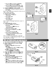
...of the open or close cycle. Door reverses CLO E PEN MORE ORE MT E R O M RE R RC D A CLOS PEN N NclOosTeE:cyDcoloe.r automatically stops at the garage door and press the button. BATTERY / VISOR CLIP INSTALLATION 1. straight IN on power head Lcboueadttreonn - - 1M0emseocroynidsseorarsuendtil light goes out • Program door operator again • Press remote control button once within 30 seconds - battery cover snaps open or LIMIT ADJUSTMENT D U S P t t N 5 43 7 4 5 2 1 869 PRO-MAX 4. iNsOfoTrEa: Edaifcfehrebnutttoopneorantoarm. Turn remote...
...of the open or close cycle. Door reverses CLO E PEN MORE ORE MT E R O M RE R RC D A CLOS PEN N NclOosTeE:cyDcoloe.r automatically stops at the garage door and press the button. BATTERY / VISOR CLIP INSTALLATION 1. straight IN on power head Lcboueadttreonn - - 1M0emseocroynidsseorarsuendtil light goes out • Program door operator again • Press remote control button once within 30 seconds - battery cover snaps open or LIMIT ADJUSTMENT D U S P t t N 5 43 7 4 5 2 1 869 PRO-MAX 4. iNsOfoTrEa: Edaifcfehrebnutttoopneorantoarm. Turn remote...
Owner's Manual
Page 28
...; Plug a lamp into insulation, they can short wires. Door will only run from wall control. Lights will only run closed . Check CLOSE limit switch setting (See Section 8) Check for power head. Check CLOSE limit switch for no reason. Relocate remote control inside car. Do Not attempt to operator. Check force adjustment (See section7). Make sure carriage is in good repair, properly lubricated and balanced (See Monthly Maintenance section). Use self-diagnostic STB System troubleshooting information to reset. SOLUTIONS Check lock switch...
...; Plug a lamp into insulation, they can short wires. Door will only run from wall control. Lights will only run closed . Check CLOSE limit switch setting (See Section 8) Check for power head. Check CLOSE limit switch for no reason. Relocate remote control inside car. Do Not attempt to operator. Check force adjustment (See section7). Make sure carriage is in good repair, properly lubricated and balanced (See Monthly Maintenance section). Use self-diagnostic STB System troubleshooting information to reset. SOLUTIONS Check lock switch...
Owner's Manual
Page 29
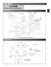
WIRING DIAGRAM CAUTION Opening cover could cause electrical shock. (Stealth Motor) FOR HELP-1.800.354.3643 OR GENIECOMPANY.COM 29 (ProMax Motor)
WIRING DIAGRAM CAUTION Opening cover could cause electrical shock. (Stealth Motor) FOR HELP-1.800.354.3643 OR GENIECOMPANY.COM 29 (ProMax Motor)


