
Owner's Manual
Page 8
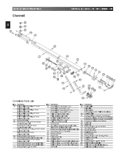
...91 92 93 94 95 96 97 98 99 Roller Chain-8' Door (Chain Only)(278.5") 100 Belt Retainer Screw, #6-32 x 1/2" Phil Pan Hd Slf Tap Carriage Slide Emerg. Release Cord-7'6" Doors(26.5") Emergency Release Cord 8' & 10' Doors(56.5") Emergency Release Cord -12' Doors(96.0") Emergency Release Knob (Red) ...Pin Screw, 3/8"-16 x .87 Hx Hd Mch Hex Nut, 3/8"-16 Curved Door Arm Straight Door Arm Door Bracket Screw, 1/4"-20 x 3/4" Hx Hd, Sf Tap Carriage Assembly Carriage Cap Screw, #10-14 x 1-5/16" Hx Hd Wall Console (Series II ) Roller Chain -10' Door (Chain Only)(328.5") 101 Wall Button (Series II ) ...
...91 92 93 94 95 96 97 98 99 Roller Chain-8' Door (Chain Only)(278.5") 100 Belt Retainer Screw, #6-32 x 1/2" Phil Pan Hd Slf Tap Carriage Slide Emerg. Release Cord-7'6" Doors(26.5") Emergency Release Cord 8' & 10' Doors(56.5") Emergency Release Cord -12' Doors(96.0") Emergency Release Knob (Red) ...Pin Screw, 3/8"-16 x .87 Hx Hd Mch Hex Nut, 3/8"-16 Curved Door Arm Straight Door Arm Door Bracket Screw, 1/4"-20 x 3/4" Hx Hd, Sf Tap Carriage Assembly Carriage Cap Screw, #10-14 x 1-5/16" Hx Hd Wall Console (Series II ) Roller Chain -10' Door (Chain Only)(328.5") 101 Wall Button (Series II ) ...

Owner's Manual
Page 10
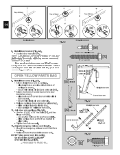
... hex NOTE:Chaininner-slideorbeltbullet should remainat tmraidv-etlrawvheelnwsheetntinagssliemmitbsl.ing to power head to powerhead . • Align mounting holes in carriage lever. • Wrap wire around itself, tie securely. Placepowerheadandchannelonclean,flatsurface. 4. Place power head and rail on the ...rail FOR HELP-1.800.354.3643 OR GENIECOMPANY.COM Toward Door Toward Power Head Carriage ERTamegleeragseency ERCmoelreedragseency ERKmenloeebragseency Fig. 1-1 [69]Hex Head Screws "D" -Shaft and Hole Fig. 1-2 [69] No. 10 x 1/2" ...
... hex NOTE:Chaininner-slideorbeltbullet should remainat tmraidv-etlrawvheelnwsheetntinagssliemmitbsl.ing to power head to powerhead . • Align mounting holes in carriage lever. • Wrap wire around itself, tie securely. Placepowerheadandchannelonclean,flatsurface. 4. Place power head and rail on the ...rail FOR HELP-1.800.354.3643 OR GENIECOMPANY.COM Toward Door Toward Power Head Carriage ERTamegleeragseency ERCmoelreedragseency ERKmenloeebragseency Fig. 1-1 [69]Hex Head Screws "D" -Shaft and Hole Fig. 1-2 [69] No. 10 x 1/2" ...
Owner's Manual
Page 14
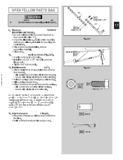
in • -Resleecausreecwairtrhiacgleev(isSepeineamnedrgcoetntecrypreinle. ase tag). - - slide stop carriage carriage towards closed door. 14" minimum from • Retie overhand knot and trim excess cord. J• ofUliansnedgtoewonoru(at2sr)m[39/.... 10. GSYoStoTESMecItNioSnT3A-LSLAAFTEIO-TN-B.EAM® - "V" Top of Door orte "V" Top of Door de la ort "V" Top of curved door arm to carriage. - dsloiporsbhroarctkeent.d of - sceacrruiaregewaiths schleovwisnp. PROCEED TO PAGE 18 - [90]Clevis pin Straight door arm Curved door arm [89]Cotter pin Fig. 2-7...
in • -Resleecausreecwairtrhiacgleev(isSepeineamnedrgcoetntecrypreinle. ase tag). - - slide stop carriage carriage towards closed door. 14" minimum from • Retie overhand knot and trim excess cord. J• ofUliansnedgtoewonoru(at2sr)m[39/.... 10. GSYoStoTESMecItNioSnT3A-LSLAAFTEIO-TN-B.EAM® - "V" Top of Door orte "V" Top of Door de la ort "V" Top of curved door arm to carriage. - dsloiporsbhroarctkeent.d of - sceacrruiaregewaiths schleovwisnp. PROCEED TO PAGE 18 - [90]Clevis pin Straight door arm Curved door arm [89]Cotter pin Fig. 2-7...
Owner's Manual
Page 17
... short end of assembled door arms to drywall, particle board, Cur 9. xactly as shown (Fig. 2-16). slip curved door arm into slot in carriage. - Adjust emergenc d length. • Mount the emergency release knob 6 feet from the floor. • Retie overhand knot and trim excess cord...pin d_39905_38124_14.0 [89]Cotter pin Decide which mounting Fig. 2-16 method you will use. Fig. 2-17 • Attach straight end of curved door arm to carriage. - Clevis pin[[8990]] • Overlap arms by two (2) holes. • Install two (2) 3/8" x 7/8" hex bolts, and hex flange nuts. &#...
... short end of assembled door arms to drywall, particle board, Cur 9. xactly as shown (Fig. 2-16). slip curved door arm into slot in carriage. - Adjust emergenc d length. • Mount the emergency release knob 6 feet from the floor. • Retie overhand knot and trim excess cord...pin d_39905_38124_14.0 [89]Cotter pin Decide which mounting Fig. 2-16 method you will use. Fig. 2-17 • Attach straight end of curved door arm to carriage. - Clevis pin[[8990]] • Overlap arms by two (2) holes. • Install two (2) 3/8" x 7/8" hex bolts, and hex flange nuts. &#...
Owner's Manual
Page 22
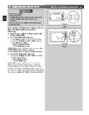
Before starting main limit switch settings, LOCK carriage onto rail assembly (See emergency release tag). 1. Raise the door until door contacts the... COE 1 2 NEC CLASS 2 3 4 MORE MORE CLO E O EN L MIT ADJUSTMENT PUSH TO SET LIM TS PUSH TO SET LIMITSC STEALTH ORSE ONLY IE II CO NOTE U E ONLY W TH SER E CON ROL CLOSE MORE OPEN MORE CLOSE OPEN EIMIT ADJUSTMENT S Patent No ... set switch on back of power head. • Push and hold limit set switch until the carriage engages with the inner-slide/bullet. 2. 6... release the limit set switch until door moves to operate door.
Before starting main limit switch settings, LOCK carriage onto rail assembly (See emergency release tag). 1. Raise the door until door contacts the... COE 1 2 NEC CLASS 2 3 4 MORE MORE CLO E O EN L MIT ADJUSTMENT PUSH TO SET LIM TS PUSH TO SET LIMITSC STEALTH ORSE ONLY IE II CO NOTE U E ONLY W TH SER E CON ROL CLOSE MORE OPEN MORE CLOSE OPEN EIMIT ADJUSTMENT S Patent No ... set switch on back of power head. • Push and hold limit set switch until the carriage engages with the inner-slide/bullet. 2. 6... release the limit set switch until door moves to operate door.
Owner's Manual
Page 28
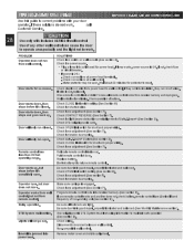
.... • Plug a lamp into receiver memory (See section 9). Door starts for power head. Check force adjustment (See section7). Check force adjustment (See section 7). Make sure carriage is engaged. Program remote control code into outlet used for no reason. Non-compatible wall control. Check force adjustment (See Section 7). TROUBLESHOOTING GUIDE Use this...
.... • Plug a lamp into receiver memory (See section 9). Door starts for power head. Check force adjustment (See section7). Check force adjustment (See section 7). Make sure carriage is engaged. Program remote control code into outlet used for no reason. Non-compatible wall control. Check force adjustment (See Section 7). TROUBLESHOOTING GUIDE Use this...


