
Genie ProMax Stealth Support Question
Genie ProMax Stealth Support Question
Find answers below for this question about Genie ProMax Stealth.Need a Genie ProMax Stealth manual? We have 1 online manual for this item!
Question posted by sandrachurch on May 10th, 2014
Promax Stealth Anx700
we have a Promax Stealth garage door opener model ANX700. We are trying to figure out how to program the unit for the remote bulit into my car. we cannot find the learn button on the unit. Is it too old? If so, how do we program it?
Current Answers
Related Genie ProMax Stealth Manual Pages
Owner's Manual - Page 1
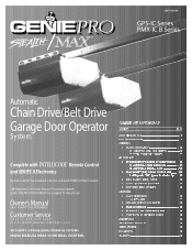
...Garage Door Operator
System
Complete with and SERIES II Electronics
Remote Control
Operator MUST be installed with the included SERIES II Wall Control! Owner's Manual
SAVE FOR FUTURE REFERENCE
Customer Service
CALL: 1-800-354-3643 VISIT: WWW.GENIECOMPANY.com
AUTOMATIC GARAGE DOOR... .
23 23
8 FINE LIMIT SWITCH ADJUSTMENTS 24
9 REMOTE CONTROLS 24-25
10 BATTERY & VISOR CLIP INSTALLATION 25
...
Owner's Manual - Page 2
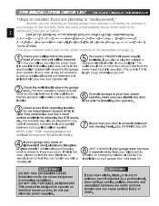
...Dealer.
7 Insure that they can furnish you with your new door operator kit)
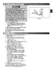
Check the wall directly above the garage
2 door. If you plan to plug the unit into a
Plan how you will be mounted
You need to ...luberoniyyordsuaie,ssrbpoirernaouxjcfutterkroeseyfmstsoieorannadl. SEE WARNING BELOW
4 Is your garage door made of your new unit will be mounting the power head standard electrical ...
Owner's Manual - Page 4
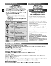
... not understand an instruction, call your service representative.
2. SAFETY FEATURES (varies by model)
Safe-T-Beam® (STB) Non-Contact Reversing System Places an invisible beam across door opening and closing door For maximum safety set the minimum force required to fully open and close door Automatic Lighting System One or two light bulbs (depending on when...
Owner's Manual - Page 6
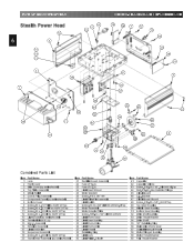
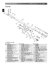
PARTS IDENTIFICATION
Stealth Power Head
12
6
3
15 14 12
2 20
1
6 5 4
FOR HELP-1.800.354.3643 OR GENIECOMPANY.COM
19
16 7
12
17
12
11 18 19... Tap 11 Screw, #8 x .50 Slt Hx Hd/W Sf Tap 12 Screw, #8 x .38 Slt Hx Hd/W Sf Tap 13 Light Socket (by series/model)
Item Part Name 21 Rectifier Board Assembly 22 Fuse (F1), UL 23 Fuse (F2), UL 24 Limit Gear Shroud 25 Motor Bracket 26 Screw, #10...
Owner's Manual - Page 8
... Door (Belt Models Only) Belt & Bullet Assembly - 8' Door (Belt Models Only) Belt & Bullet Assembly - 10' Door (Belt Models Only) Belt & Bullet Assembly - 12' Door (Belt Models Only)
67 Sprocket Bushing 68 Sprocket, 10 Tooth - 7'6" & 8' Doors
(Chain Models Only) Sprocket, 12 Tooth - 10' Door (Chain Models Only) Drive Sprocket, 18 Tooth - 7'6" & 8' Doors (Belt Models Only) Drive Sprocket - 10' Door...
Owner's Manual - Page 10

...shaft flush with power head. 5. wn over "D"-shaft on the rail
FOR HELP-1.800.354.3643 OR GENIECOMPANY.COM
Toward Door
Toward Power Head
Carriage
ERTamegleeragseency ERCmoelreedragseency ERKmenloeebragseency
Fig. 1-1
[69]Hex Head Screws
"D" -Shaft and Hole
Fig. 1-2
...tlhimeitdsouonr.til 3. 1...OPERATOR ASSEMBLY
OPEN BLUE PARTS BAG Screws fobraga....
Owner's Manual - Page 11
...source of power until instructed to the wall button or console. Install the emergency release tag ...8. An improperly balanced door could cause severe injury...:
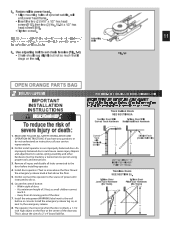
1. Install door operator 7 feet...Doors...Trackless Doors SEE SECTION 2B. 5. Fasten rail to the door before...the door contacts a 1-1/2 inch high object on an improperly balanced door. Locate the control button: • Within sight of door. &#...
Owner's Manual - Page 13
... with cardboard packing. -
center hole is same.
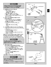
• Support power head above door tracks.
• Open door. • Level channel/rail assembly and
HBreaacdkeert
Sp[e8e1d n]ut
Cold phineader
support temporarily... bracket so: - CAUTION
Header bracket must be fastened to garage fbroaamrdin,gp.laDsoteNrootrfaosthteenr stoucdhrymwaatlel,rpiaalsrt.icle
Line "V"
"B"
"A"
Header...
Owner's Manual - Page 14
... faorreumseeawnitth bccooennrBcteaeqecructnaiyiruneosgdueryadodnouodoroarrdddomdeoiastrin.iogunnfaaslcvmtuaarrtyee,rrmiwaoiltsdhnifaiecneaydtieqodun.esPsmtlieoaanysse
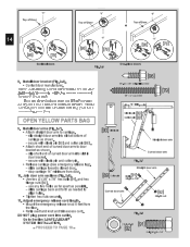
OPEN YELLOW PARTS BAG
[96]
1/4"-20 x 3/4" Self-Drilling Screw 1/4" x 2" Lag Screw
[79]
14" MIN. PROCEED TO PAGE 18 -
[90]Clevis pin
Straight door arm
Curved door arm
[89]Cotter pin
Fig. 2-7
Straight door arm
B3/o8l-t1,6[9x17...
Owner's Manual - Page 15
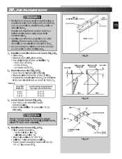
... line "H" at marked positions. • F1/a4s"texn2h"elaagdesrcrberwacsk[e7t9t]o. down door about 20".
2. Determine door rise (Fig. 2-10). • Open door to highest point of travel. • Measure distance from top of door and header (Fig. 2-9). • Close door. • Measure door width. dll,tpoagrtaircalegeboard,
Floor
Floor
Fig. 2-10
Line "V"
"A" Line "H"
"B" Header bracket...
Owner's Manual - Page 18
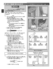
...,wSmaTyoBre
• Sunlitdileitscoluicrkcse/isnetonspolarcoent(oFitgo.n3g-u3e).of bracket
OPEN RED PARTS BAG
3.
• •
RS- SAFE...on next page and
Figure 3-4 before attaching.)
RED LED
GREEN LED
GREEN LED
RED RED LED LED
GREEN LED
ONE DOOR GARAGE
TWO DOOR GARAGE
GREEN LED
RED RED LED LED
GREEN GREEN LED LED
RED LED
THREE DOOR GARAGE
FIG. 3-4 STB...
Owner's Manual - Page 19
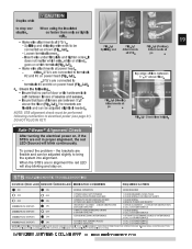
.... 3-6
FIG. 3-7
Splitting and AttaatcShmTBe.nts
FIG. 3-8 (ProMax)
Apttoachments
at STB's.
3
19
- STB's are connected to...door or its hardware is in
3 4
path between 5"-6" The brackets are between lenses of source and sensor.
•
Insure above
tthheatfltoooprs(oFfigle.n3s-9e)s. FIG. 3-8 (Stealth...
1.CHECK ALIGNMENT 2.
HOLD WALL CONTROL BUTTON
CUSTOMER SERVICE: 1.800.354.3643 or...
Owner's Manual - Page 20
...system is completely closed
- Dr .
1. At least 5 feet from
3 inside garage
4
-
MORE
OPEN MENT
W1 2
Y3 G4
PUSH TO SET L MITS
Rpoewaer rviheewadof
Power head
terminals 1 ...Button
- 4... om po
ol.
• Place the wall control:
-
Vacation Locking Switch
1
-
Connect striped wires to terminal "1" Lon power head and "W" on wall control.
- Open and closes door...
Owner's Manual - Page 21
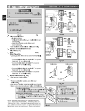
...screws from the branch 2. For Stealth-connect permanent wiring to internal terminal ...• Replace and tighten four (4) hex head screws. The door
pOowpeerractoorrd
operator must remain off . 3. Install permanent wiring to green... knock-out plug. • Install a suitable entrance bushing. 4. For ProMax-connect permanent wiring. • Make connections with UL recognized wire nuts. ...
Owner's Manual - Page 22
.... - 6... Raise the door until door moves
to operate door. FOR HELP-1.800.354.3643 OR GENIECOMPANY.COM
O EN COE
1
2 NEC CLASS 2 3
4
MORE
MORE
CLO E
O EN
L MIT ADJUSTMENT
PUSH TO SET LIM TS
PUSH TO SET
LIMITSC
STEALTH
ORSE ONLY
IE II CO
NOTE U E ONLY W TH
SER E CON ROL
CLOSE MORE
OPEN MORE
CLOSE
OPEN
EIMIT ADJUSTMENT...
Owner's Manual - Page 23
....
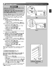
NOTE: Set minimum force required to turn adjusting screw.
• Operate door using wall control. • Repeat force adjustment until door reverses. FOR HELP-1.800.354.3643 OR GENIECOMPANY.COM
STEALTH
OP N CL SE
OR
LIMIT SET
OPEN FORCE
CLOSE FORCE RADIO SIGNAL LEARN CODE
PRO MAX
MORE FORCE
Fig. 7-1
1
2 NEC
CLASS 2
3
4
MO E
MORE
C OSE...
Owner's Manual - Page 24
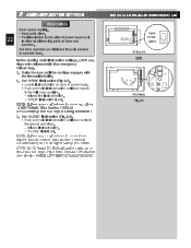
.... - Adjust the "CLOSE" limit switch (Fig. 8-1).
• Run door fully closed by pushing wall control.
24
• Locate curved "OPEN" limit adjustment slot on back of power head.
• Look into slot for protector to open less.
2. Program one-button remote (Fig. 9-1)
• Locate learn code button and learn code button on next page)
FOR HELP-1.800.354.3643 OR...
Owner's Manual - Page 25
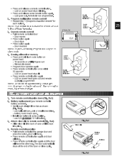
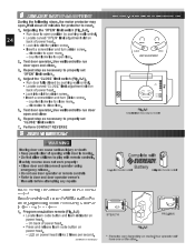
...Operate remote control
STEALTH
Lcboueadttreonn
25
• Point remote control at the garage door and
press the button. battery cover snaps open or
LIMIT ADJUSTMENT
D
U S P t t N 5 43 7 4 5 2 1 869
PRO-MAX
4. iNsOfoTrEa: Edaifcfehrebnutttoopneorantoarm. Erasing all receiver memory • Press and hold learn code button on power head goes out and remote control is programmed...
Owner's Manual - Page 28
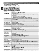
... are tight. Check force adjustment (See section 7). Replace battery. Check force adjustment (See section7). Program remote control code into outlet used for power head.
Check connections at door.
Door will not go out.
from receiver memory and reprogram. Wall control button sticking.
Check Safe-T-Beam® System(See section 3). Check force adjustment (See Section 7). Relocate...
Owner's Manual - Page 29
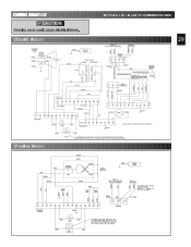
WIRING DIAGRAM CAUTION
Opening cover could cause electrical shock.
(Stealth Motor)
FOR HELP-1.800.354.3643 OR GENIECOMPANY.COM
29
(ProMax Motor)
Similar Questions

What Remote Do I Use For Powerlift Garage Door Opener Model Wr77 Serial No.08258
(Posted by tmski87 3 years ago)

Forhandler I Danmark Genie Pro Stealth
forhandler i danmarkgenie pro stealth
forhandler i danmarkgenie pro stealth
(Posted by len28923 8 years ago)

Where Is The Learn Button On My Genie Silentmax 1000 Garage Door Opener
(Posted by xEPmoor 9 years ago)

Genie Pro Max Stealth
The Motor Is Running But The Shaft Is Not Turning, What Is The Problem?
The Motor Is Running But The Shaft Is Not Turning, What Is The Problem?
(Posted by KYHERLEE 11 years ago)
Pro Max Stealth 1200 Garage Door Will Not Close
Before it would be able to close with 1 touch of the button. Now you have to keep the button pushed ...
Before it would be able to close with 1 touch of the button. Now you have to keep the button pushed ...
(Posted by firelos 11 years ago)