

Owner's Manual
Page 1
... OF CONTENTS Safety Information 2 Important Installation Instructions 2 Safety Features 2 Pre-installation Checklist 3 Garage Door Opener Assembly 9 Record Data (for 8' Doors Included Wall Control MUST be Properly Set to Operation of this Garage Door Operator. Please call us: 1-800-35-GENIE (354-3643) www.geniecompany.com Please have Model information ready when calling. Need Help...
... OF CONTENTS Safety Information 2 Important Installation Instructions 2 Safety Features 2 Pre-installation Checklist 3 Garage Door Opener Assembly 9 Record Data (for 8' Doors Included Wall Control MUST be Properly Set to Operation of this Garage Door Operator. Please call us: 1-800-35-GENIE (354-3643) www.geniecompany.com Please have Model information ready when calling. Need Help...

Owner's Manual
Page 2
... and adjustments to cables, spring assembly, and other like items. • Repairs and adjustments must reverse when the door contacts a 1-1/2 inch high object on the floor at 1-800-35-GENIE.. If you have any questions or do not understand the information presented, call your nearest... down travel to set the minimum force required to 60 Watts max. If you have garage door related questions or do not understand an instruction, call 1-800-35-GENIE or visit www.geniecompany.com IMPORTANT INSTALLATION INSTRUCTIONS WARNING: TO REDUCE THE RISK OF SEVERE INJURY OR ...
... and adjustments to cables, spring assembly, and other like items. • Repairs and adjustments must reverse when the door contacts a 1-1/2 inch high object on the floor at 1-800-35-GENIE.. If you have any questions or do not understand the information presented, call your nearest... down travel to set the minimum force required to 60 Watts max. If you have garage door related questions or do not understand an instruction, call 1-800-35-GENIE or visit www.geniecompany.com IMPORTANT INSTALLATION INSTRUCTIONS WARNING: TO REDUCE THE RISK OF SEVERE INJURY OR ...
Owner's Manual
Page 3
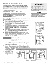
... any additional items you have it moves freely (Figure 1). KEEP FEET CLEAR OF DOOR 3' - 4' Sectional Door Check Step 2: CHECK GARAGE DOOR ALIGNMENT, OPERATION, AND BALANCE A Raise door, check alignment and see if it adjusted by a Genie Factory Authorized Dealer. Make a note of your Genie Factory Authorized Dealer or dealer of whether it is a sectional or a one...
... any additional items you have it moves freely (Figure 1). KEEP FEET CLEAR OF DOOR 3' - 4' Sectional Door Check Step 2: CHECK GARAGE DOOR ALIGNMENT, OPERATION, AND BALANCE A Raise door, check alignment and see if it adjusted by a Genie Factory Authorized Dealer. Make a note of your Genie Factory Authorized Dealer or dealer of whether it is a sectional or a one...
Owner's Manual
Page 4
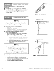
... line to "H". For one-piece doors, add 6" to connect points. Check Step 3: MEASURE GARAGE DOOR HEIGHT Measure garage door height (7'-6", 8'-0", or taller) with at least a 3" space above the Header Bracket mounting point, contact a Genie Factory Authorized Dealer. • If a door spring is above Header, a 2"... x 6" board must be screwed to studs beside your mark to open the garage door. If there is any question contact your rail is above ...
... line to "H". For one-piece doors, add 6" to connect points. Check Step 3: MEASURE GARAGE DOOR HEIGHT Measure garage door height (7'-6", 8'-0", or taller) with at least a 3" space above the Header Bracket mounting point, contact a Genie Factory Authorized Dealer. • If a door spring is above Header, a 2"... x 6" board must be screwed to studs beside your mark to open the garage door. If there is any question contact your rail is above ...
Owner's Manual
Page 5
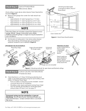
...; Approximately 14' back if garage has an 12' 0" door. Contact a licensed electrician for installation. • If building codes require permanent wiring, Power Head must be needed for your installation. See page 19 NOTE Permanent wiring must be installed. For Help, call 1-800-35-GENIE or visit www.geniecompany.com 5 Additional mounting straps...
...; Approximately 14' back if garage has an 12' 0" door. Contact a licensed electrician for installation. • If building codes require permanent wiring, Power Head must be needed for your installation. See page 19 NOTE Permanent wiring must be installed. For Help, call 1-800-35-GENIE or visit www.geniecompany.com 5 Additional mounting straps...
Owner's Manual
Page 6
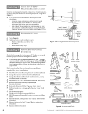
... to wood frame: • Concrete screws and concrete anchors (not included) must be used to install a Genie Emergency Release Kit (GER-2). available from the garage door before starting the installation. Check Step 7: CHECK SAFE-T-BEAM® MOUNTING BRACKET LOCATION Check for Safe-T-Beam®... (6" above floor Figure 7 Mounting Safe-T-Beam® Components Check SteDp 9: REMOVE EXISTING GARAGE DOOR LOCKS Check that the garage door locks, rope, and T-Handles are removed from a Genie Factory Authorized Dealer or through Accessories Order Form on pages 31/32.) Before going further, get...
... to wood frame: • Concrete screws and concrete anchors (not included) must be used to install a Genie Emergency Release Kit (GER-2). available from the garage door before starting the installation. Check Step 7: CHECK SAFE-T-BEAM® MOUNTING BRACKET LOCATION Check for Safe-T-Beam®... (6" above floor Figure 7 Mounting Safe-T-Beam® Components Check SteDp 9: REMOVE EXISTING GARAGE DOOR LOCKS Check that the garage door locks, rope, and T-Handles are removed from a Genie Factory Authorized Dealer or through Accessories Order Form on pages 31/32.) Before going further, get...

Owner's Manual
Page 7
... 3/8" Hex Head No. 8-32 x 1" Phillips Screw No. 8-32 x 3/8" Slotted Hex Head Screw Power Cord For Help, call 1-800-35-GENIE or visit www.geniecompany.com 7 These items will be illustrated throughout the manual as required. Parts List Item 1 2 3 4 4A 4B 4C ... (long)(yellow) 10'&12'only Emergency Release Knob (green bag) 1 1 Emergency Release Tag (green bag) 1 1 Header Bracket (orange bag) 1 1 Door Bracket (orange bag) 1/4" x 2" Lag Screw (orange bag) Straight Door Arm (main carton) 1 1 varies/model 8 1 1 Clevis Pin, 3/8" x 15/16" (yellow bag) 2 2 Cotter Pin, .073" dia. ...
... 3/8" Hex Head No. 8-32 x 1" Phillips Screw No. 8-32 x 3/8" Slotted Hex Head Screw Power Cord For Help, call 1-800-35-GENIE or visit www.geniecompany.com 7 These items will be illustrated throughout the manual as required. Parts List Item 1 2 3 4 4A 4B 4C ... (long)(yellow) 10'&12'only Emergency Release Knob (green bag) 1 1 Emergency Release Tag (green bag) 1 1 Header Bracket (orange bag) 1 1 Door Bracket (orange bag) 1/4" x 2" Lag Screw (orange bag) Straight Door Arm (main carton) 1 1 varies/model 8 1 1 Clevis Pin, 3/8" x 15/16" (yellow bag) 2 2 Cotter Pin, .073" dia. ...
Owner's Manual
Page 8
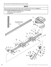
One-Piece Rail Assembly (Genie Pro only) for 10' or 12' door includes: • Special "Close" Limit Switch with longer Wires. • 96" Emergency Release Cord (yellow). • Rail Support Kit. 11 Rail Assembly (1 piece) (Packaged separately) 5573 3 4466 5544 1199 1111 DOOR 26 30 88 11 47C 1166 1155 2211 1188 ...88 1133 DOOR 1144 553 22 99 45A 1100 46B 3311 30 28 556 3322 3366 3344 333 32 112 3333 2225 2222 23 2244 3355 8 For Help, call 1-800-35-GENIE or visit www.geniecompany.com EXCELERATOR HARDWARE EXPLODED VIEW NOTE ...
One-Piece Rail Assembly (Genie Pro only) for 10' or 12' door includes: • Special "Close" Limit Switch with longer Wires. • 96" Emergency Release Cord (yellow). • Rail Support Kit. 11 Rail Assembly (1 piece) (Packaged separately) 5573 3 4466 5544 1199 1111 DOOR 26 30 88 11 47C 1166 1155 2211 1188 ...88 1133 DOOR 1144 553 22 99 45A 1100 46B 3311 30 28 556 3322 3366 3344 333 32 112 3333 2225 2222 23 2244 3355 8 For Help, call 1-800-35-GENIE or visit www.geniecompany.com EXCELERATOR HARDWARE EXPLODED VIEW NOTE ...
Owner's Manual
Page 9
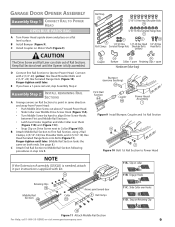
... Middle Rail Section to Middle Rail Section following procedures in same direction and away from Power Head: • Push Middle Drive Screw out about 2" toward door 11C. See page 8.) C Attach End Rail Section to First Rail Section, using 2 Rail Clamps, 4 (5/16"-18) Hex Shoulder Bolts, and 4 (5/16"-18) Hex ... them (Figure 11B) and (Figure 11C). • Snap Clip on Retaining Clip 10 Figure 11 Attach Middle Rail Section For Help, call 1-800-35-GENIE or visit www.geniecompany.com 9 CAUTION The Drive Screw and Rail Liner can slide out of Rail Sections. Rail Strap 15 5/16"-18 Hex Head...
... Middle Rail Section to Middle Rail Section following procedures in same direction and away from Power Head: • Push Middle Drive Screw out about 2" toward door 11C. See page 8.) C Attach End Rail Section to First Rail Section, using 2 Rail Clamps, 4 (5/16"-18) Hex Shoulder Bolts, and 4 (5/16"-18) Hex ... them (Figure 11B) and (Figure 11C). • Snap Clip on Retaining Clip 10 Figure 11 Attach Middle Rail Section For Help, call 1-800-35-GENIE or visit www.geniecompany.com 9 CAUTION The Drive Screw and Rail Liner can slide out of Rail Sections. Rail Strap 15 5/16"-18 Hex Head...

Owner's Manual
Page 10
...Assembly 22 Wire Clips 53 19Brown Wire 24 Emergency Release Cord 25 C Place Switches on Assembled Rail 10 For Help, call 1-800-35-GENIE or visit www.geniecompany.com Insert (#8-32 x 1") Hex Head Screw into Switch hole and finger-tighten until later. Close Limit Switch (Brown ... Rail Sections so Magnetic Carriage Assembly can slide freely along length of Rail. Magnetic Carriage Assembly 12 Engaged Position Release Position Puerta Door Porte Toward door and header Toward Power Head End Rail Section 4C Figure 12 Slide Magnetic Carriage onto Rail Assembly Step C4H: ATTACH RAIL STRAP...
...Assembly 22 Wire Clips 53 19Brown Wire 24 Emergency Release Cord 25 C Place Switches on Assembled Rail 10 For Help, call 1-800-35-GENIE or visit www.geniecompany.com Insert (#8-32 x 1") Hex Head Screw into Switch hole and finger-tighten until later. Close Limit Switch (Brown ... Rail Sections so Magnetic Carriage Assembly can slide freely along length of Rail. Magnetic Carriage Assembly 12 Engaged Position Release Position Puerta Door Porte Toward door and header Toward Power Head End Rail Section 4C Figure 12 Slide Magnetic Carriage onto Rail Assembly Step C4H: ATTACH RAIL STRAP...
Owner's Manual
Page 12
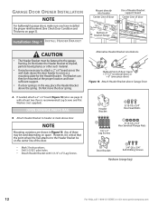
...used depending on page 3). Any of door travel + 2-1/2" (sectional door) or + 6" (one-piece door) Figure 18 Attach Header Bracket above the spring. GARAGE DOOR OPENER INSTALLATION NOTE For lightweight garage doors, make sure you have sufficient support. • If a door spring is in Figure 18. NOTE ...Head Bolts 11 5/16-18 x 3/4" Hex Serrated Flange Nuts 28 Door Bracket 56 1/4"-20 x 3/4" Self-Drilling Screws Hardware (orange bag) 12 For Help, call 1-800-35-GENIE or visit www.geniecompany.com Do Not move the door spring. However, it is recommended) Lag Screws and Flat Washers ...
...used depending on page 3). Any of door travel + 2-1/2" (sectional door) or + 6" (one-piece door) Figure 18 Attach Header Bracket above the spring. GARAGE DOOR OPENER INSTALLATION NOTE For lightweight garage doors, make sure you have sufficient support. • If a door spring is in Figure 18. NOTE ...Head Bolts 11 5/16-18 x 3/4" Hex Serrated Flange Nuts 28 Door Bracket 56 1/4"-20 x 3/4" Self-Drilling Screws Hardware (orange bag) 12 For Help, call 1-800-35-GENIE or visit www.geniecompany.com Do Not move the door spring. However, it is recommended) Lag Screws and Flat Washers ...

Owner's Manual
Page 13
... other lightweight materials must be properly braced before mounting door Opener. For one-piece doors: A Position Door Bracket on door's center line, as high as possible or on door Optional Door Operator Bracket (not included) Figure 19 Attach Door Bracket Rail Strap Rail Strap Bolt 26 11 Header Bracket... For sectional doors: A Place Door Bracket on door center line, no OR lower than top rollers Attach at highest point on top of door Attach no lower than 2", use 3 (1/4" x 2") Lag Screws. B Attach (5/16"-18) Flange Nut to Header Bracket For Help, call 1-800-35-GENIE or visit ...
... other lightweight materials must be properly braced before mounting door Opener. For one-piece doors: A Position Door Bracket on door's center line, as high as possible or on door Optional Door Operator Bracket (not included) Figure 19 Attach Door Bracket Rail Strap Rail Strap Bolt 26 11 Header Bracket... For sectional doors: A Place Door Bracket on door center line, no OR lower than top rollers Attach at highest point on top of door Attach no lower than 2", use 3 (1/4" x 2") Lag Screws. B Attach (5/16"-18) Flange Nut to Header Bracket For Help, call 1-800-35-GENIE or visit ...

Owner's Manual
Page 14
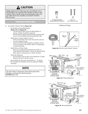
...Do Not fasten to garage ceiling. H ONE-PIECE DOORS Set clearance at 1"-11/2" between Rail and door at highest point of travel by raising the door to check. H Figure 21 Checking Power Head ... TO GARAGE A Raise and support Opener Power Head (along door center line) higher than the highest point of door travel . SECTIONAL DOORS Rail Should be needed. Check for mounting Opener Power Head to... Make sure the rail of your supported Power Head is slightly higher than highest point of door travel (using Lag Screws. (Angle iron not included) Figure 22 Mounting methods for open beam ...
...Do Not fasten to garage ceiling. H ONE-PIECE DOORS Set clearance at 1"-11/2" between Rail and door at highest point of travel by raising the door to check. H Figure 21 Checking Power Head ... TO GARAGE A Raise and support Opener Power Head (along door center line) higher than the highest point of door travel . SECTIONAL DOORS Rail Should be needed. Check for mounting Opener Power Head to... Make sure the rail of your supported Power Head is slightly higher than highest point of door travel (using Lag Screws. (Angle iron not included) Figure 22 Mounting methods for open beam ...

Owner's Manual
Page 15
...• Pull Cord through Magnetic Carriage Assembly Lever until Knob is as short as possible 35 32 Curved 36 34 Door Arm 31 Straight Door Arm 33 For Help, call 1-800-35-GENIE or visit www.geniecompany.com Figure 24 Assemble Arms (ONE-PIECE) 15 Installation SteCpH5: ASSEMBLE AND CONNECT... DOOR ARMS OPEN YELLOW PARTS BAG For sectional doors: A Attach Curved Door Arm to Door Bracket with Clevis Pin and Cotter Pin (Figure 24). B Attach ...
...• Pull Cord through Magnetic Carriage Assembly Lever until Knob is as short as possible 35 32 Curved 36 34 Door Arm 31 Straight Door Arm 33 For Help, call 1-800-35-GENIE or visit www.geniecompany.com Figure 24 Assemble Arms (ONE-PIECE) 15 Installation SteCpH5: ASSEMBLE AND CONNECT... DOOR ARMS OPEN YELLOW PARTS BAG For sectional doors: A Attach Curved Door Arm to Door Bracket with Clevis Pin and Cotter Pin (Figure 24). B Attach ...

Owner's Manual
Page 16
...Figure 27). NOTE To help prevent interference from wall far enough so tongue of garage door frame or wall 6" above floor Figure 27 Final Check Safe-T-Beams® 16 For Help, call 1-800-35-GENIE or visit www.geniecompany.com A Install Safe-T-Beam® Source and Sensor (Figure...BEAM® SYSTEM ELECTRICAL WARNING Ensure there is No power to Brackets (Figure 25): • For single-door garages. - NOTE Mounting Brackets can be placed further away from a Genie Factory Authorized Dealer or through the Accessories Order Form. - If not, Safe-TBeam® Mounting Bracket Extensions ...
...Figure 27). NOTE To help prevent interference from wall far enough so tongue of garage door frame or wall 6" above floor Figure 27 Final Check Safe-T-Beams® 16 For Help, call 1-800-35-GENIE or visit www.geniecompany.com A Install Safe-T-Beam® Source and Sensor (Figure...BEAM® SYSTEM ELECTRICAL WARNING Ensure there is No power to Brackets (Figure 25): • For single-door garages. - NOTE Mounting Brackets can be placed further away from a Genie Factory Authorized Dealer or through the Accessories Order Form. - If not, Safe-TBeam® Mounting Bracket Extensions ...
Owner's Manual
Page 17
...slack for adjustment Terminal attachments at Power Head Figure 29 Wiring Method A Wire Clips 53 Insulated Staples 38 For Help, call 1-800-35-GENIE or visit www.geniecompany.com 654321 STB Terminal attachments at Safe-T-Beam® Terminal attachments at Power Head. - Staples should be snug only..... • Attach Wires to Safe-T-Beam® Sensors. - Ensure that tops of Lenses are connected to Terminals #2 and #3 on top of door or its hardware is in yet! 38 Insulated Staples (approximately 30 parts) 41 #6-11/4" Pan Head Screws Hardware (red bag) Approx. 11/2" ...
...slack for adjustment Terminal attachments at Power Head Figure 29 Wiring Method A Wire Clips 53 Insulated Staples 38 For Help, call 1-800-35-GENIE or visit www.geniecompany.com 654321 STB Terminal attachments at Safe-T-Beam® Terminal attachments at Power Head. - Staples should be snug only..... • Attach Wires to Safe-T-Beam® Sensors. - Ensure that tops of Lenses are connected to Terminals #2 and #3 on top of door or its hardware is in yet! 38 Insulated Staples (approximately 30 parts) 41 #6-11/4" Pan Head Screws Hardware (red bag) Approx. 11/2" ...

Owner's Manual
Page 18
.... C Ensure Vacation Lock Switch is in as far as needed to wall near Wall Console. Security Vacation Lock Switch Independent Light Control Garage Door Control NOTE More than the type included will cause a malfunction. E Attach Wall Console onto wall at location found above floor (to prevent ...least 5' above with Entrapment Warning Label 18 For Help, call 1-800-35-GENIE or visit www.geniecompany.com Makes Console easy to find in dark. • Controls door Opener from working properly and could cause the door to operate on its own. • Cut or pinched Wires can cause the...
.... C Ensure Vacation Lock Switch is in as far as needed to wall near Wall Console. Security Vacation Lock Switch Independent Light Control Garage Door Control NOTE More than the type included will cause a malfunction. E Attach Wall Console onto wall at location found above floor (to prevent ...least 5' above with Entrapment Warning Label 18 For Help, call 1-800-35-GENIE or visit www.geniecompany.com Makes Console easy to find in dark. • Controls door Opener from working properly and could cause the door to operate on its own. • Cut or pinched Wires can cause the...
Owner's Manual
Page 19
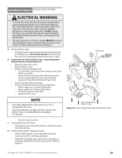
... • Use only Underwriters Laboratories, Inc. (U.L.) recognized wire nuts. • The Circuit Boards are not installing permanent wiring, go to the door Opener Must Be removed when the Motor Cover is removed. Four screws hold Motor Cover Figure 33 Connecting power with permanent wiring (Figure 33): ...or blinking (problem). • If Red LED is installed before energizing the Opener. Restore Power to page 26.) For Help, call 1-800-35-GENIE or visit www.geniecompany.com 19 This Plug will only fit into the outlet, contact a qualified electrician to Power Head Wires. - If the Plug...
... • Use only Underwriters Laboratories, Inc. (U.L.) recognized wire nuts. • The Circuit Boards are not installing permanent wiring, go to the door Opener Must Be removed when the Motor Cover is removed. Four screws hold Motor Cover Figure 33 Connecting power with permanent wiring (Figure 33): ...or blinking (problem). • If Red LED is installed before energizing the Opener. Restore Power to page 26.) For Help, call 1-800-35-GENIE or visit www.geniecompany.com 19 This Plug will only fit into the outlet, contact a qualified electrician to Power Head Wires. - If the Plug...
Owner's Manual
Page 20
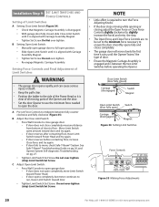
... contacting floor, move slowly the first time it runs, until it is required to turn the Force Adjusting Knobs. • If the door stops moving parts of door. • Ensure the Magnetic Carriage Assembly is engaged and is aligned with Carriage Assembly Magnet. • Tighten Set Screw. Setting Force ... 34 Setting Limit Switches Force Controls HI LO HI LO OPEN CLOSE FORCE FORCE Figure 35 Making Force Adjustments 20 For Help, call 1-800-35-GENIE or visit www.geniecompany.com B Adjust the Close Limit Switch: • Press Wall Console to run, move Limit Switch toward Power Head and...
... contacting floor, move slowly the first time it runs, until it is required to turn the Force Adjusting Knobs. • If the door stops moving parts of door. • Ensure the Magnetic Carriage Assembly is engaged and is aligned with Carriage Assembly Magnet. • Tighten Set Screw. Setting Force ... 34 Setting Limit Switches Force Controls HI LO HI LO OPEN CLOSE FORCE FORCE Figure 35 Making Force Adjustments 20 For Help, call 1-800-35-GENIE or visit www.geniecompany.com B Adjust the Close Limit Switch: • Press Wall Console to run, move Limit Switch toward Power Head and...
Owner's Manual
Page 21
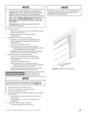
...REVERSE FUNCTION NOTE Limit Switch and Force Adjustments must contact the 2" x 4" board before checking the contact reverse function (Figure 36). D Test Door Opener: • Run door up and down a few times using Wall Console. If not, readjust the Close Limit Switch. 2" x 4" board laid flat Figure 36...For Help, call 1-800-35-GENIE or visit www.geniecompany.com 21 If not, adjust Close Force Control slightly clockwise, open garage door, and close it contacts board: • If door does not reverse, decrease Close Force until door reverses. • If door still does not reverse, move ...
...REVERSE FUNCTION NOTE Limit Switch and Force Adjustments must contact the 2" x 4" board before checking the contact reverse function (Figure 36). D Test Door Opener: • Run door up and down a few times using Wall Console. If not, readjust the Close Limit Switch. 2" x 4" board laid flat Figure 36...For Help, call 1-800-35-GENIE or visit www.geniecompany.com 21 If not, adjust Close Force Control slightly clockwise, open garage door, and close it contacts board: • If door does not reverse, decrease Close Force until door reverses. • If door still does not reverse, move ...


