

Owner's Manual
Page 1
... for Service 11 Garage Door Opener Installation 12 Accessories 22 Maintenance 25 Troubleshooting 26 Wiring Diagram 29 Warranty information 30 COMPLETE WITH INTELLICODE® REMOTE CONTROL AND SERIES II ELECTRONICS For 7' 6" Doors. Need Help? Safe-T-Beam® Safety Reverse System Must be Installed and the Force Controls MUST be installed prior to close door. Please call us: 1-800-35-GENIE (354-3643) www.geniecompany.com Please have Model information ready when calling. Having Difficulty? SAVEFTUHTIUSRMEARNEUFEARLEFNOCRE Will not operate...
... for Service 11 Garage Door Opener Installation 12 Accessories 22 Maintenance 25 Troubleshooting 26 Wiring Diagram 29 Warranty information 30 COMPLETE WITH INTELLICODE® REMOTE CONTROL AND SERIES II ELECTRONICS For 7' 6" Doors. Need Help? Safe-T-Beam® Safety Reverse System Must be Installed and the Force Controls MUST be installed prior to close door. Please call us: 1-800-35-GENIE (354-3643) www.geniecompany.com Please have Model information ready when calling. Having Difficulty? SAVEFTUHTIUSRMEARNEUFEARLEFNOCRE Will not operate...
Owner's Manual
Page 2
... • Turn off 4.5 minutes later. SAFETY INFORMATION Garage Doors are heavy objects that move with the help of springs under tension, and electric opening and closing door. Manual Emergency Release Allows the garage door to be made by a trained service person using proper tools and instructions. 3 Remove all ropes, and disable all locks connected to the door before removing operator cover. • When replacing cover, make sure wires are not pinched or near moving parts of the door. 7 Install the entrapment...
... • Turn off 4.5 minutes later. SAFETY INFORMATION Garage Doors are heavy objects that move with the help of springs under tension, and electric opening and closing door. Manual Emergency Release Allows the garage door to be made by a trained service person using proper tools and instructions. 3 Remove all ropes, and disable all locks connected to the door before removing operator cover. • When replacing cover, make sure wires are not pinched or near moving parts of the door. 7 Install the entrapment...
Owner's Manual
Page 3
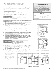
... reinforced before installing Opener. If door appears out of alignment, binds, or does not move smoothly, contact a 3' - 4' Genie Factory Authorized Dealer or dealer of your garage door for repairs and adjustments SECTIONAL DOOR, TORSION SPRINGS SECTIONAL DOOR, EXTENSION SPRINGS ONE-PIECE DOOR, TRACKLESS to door mechanism. Contact a Genie Factory Authorized Dealer or dealer of your garage door for repairs and adjustments to door mechanism. C Check door type. While checking items listed below, note...
... reinforced before installing Opener. If door appears out of alignment, binds, or does not move smoothly, contact a 3' - 4' Genie Factory Authorized Dealer or dealer of your garage door for repairs and adjustments SECTIONAL DOOR, TORSION SPRINGS SECTIONAL DOOR, EXTENSION SPRINGS ONE-PIECE DOOR, TRACKLESS to door mechanism. Contact a Genie Factory Authorized Dealer or dealer of your garage door for repairs and adjustments to door mechanism. C Check door type. While checking items listed below, note...
Owner's Manual
Page 4
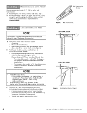
... Travel 4 For Help, call 1-800-35-GENIE or visit www.geniecompany.com Rail Extension for a stud or a solid header at your mark: (If checking a finished wall, a stud finder may be screwed to new mounting board. A Find vertical center line of Header Bracket will be installed here. - For sectional doors, add 2-1/2" to connect points. Mark this point on center line. Do Not move the door spring...
... Travel 4 For Help, call 1-800-35-GENIE or visit www.geniecompany.com Rail Extension for a stud or a solid header at your mark: (If checking a finished wall, a stud finder may be screwed to new mounting board. A Find vertical center line of Header Bracket will be installed here. - For sectional doors, add 2-1/2" to connect points. Mark this point on center line. Do Not move the door spring...
Owner's Manual
Page 6
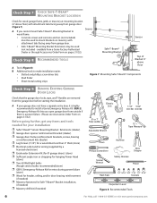
...; Safe-T-Beam® Mounting Bracket Extensions may be used (not included - Emergency Release Kit lets you cannot mount Safe-T-Beam® Mounting Bracket to wood frame: • Concrete screws and concrete anchors (not included) must be used to mount Brackets on pages 31/32). A If you open garage door from a Genie Factory Authorized Dealer or through Accessories Order Form on masonry with attachment tabs facing away from garage door (Figure 7). Check Step 7: CHECK SAFE-T-BEAM® MOUNTING BRACKET LOCATION...
...; Safe-T-Beam® Mounting Bracket Extensions may be used (not included - Emergency Release Kit lets you cannot mount Safe-T-Beam® Mounting Bracket to wood frame: • Concrete screws and concrete anchors (not included) must be used to mount Brackets on pages 31/32). A If you open garage door from a Genie Factory Authorized Dealer or through Accessories Order Form on masonry with attachment tabs facing away from garage door (Figure 7). Check Step 7: CHECK SAFE-T-BEAM® MOUNTING BRACKET LOCATION...

Owner's Manual
Page 7
.... 30 Wall Console (main carton) 1 1 #6 x 1-1/4" Pan Head Screw (red bag) 2 2 Entrapment Warning Label (manual)(main carton) 1 1 Safe-T-Beam (STB) Sensor (Green LED)(main carton) 1 1 Safe-T-Beam (STB) Source (Red LED)(main carton) 1 1 Safe-T-Beam (STB) Bracket (yellow bag) 2 2 Coupler (blue bag) 1 1 No.10 x1 1/4" Phillips Hex Head Screw (yellow bag) 1 Button Remote Control (main carton) 3 Button Remote Control (main carton) Wireless Keypad (main carton) 2 Button Remote Control (main carton) Safety & Maintenance Guide (manual)(main carton) 4 4 varies/model varies/model...
.... 30 Wall Console (main carton) 1 1 #6 x 1-1/4" Pan Head Screw (red bag) 2 2 Entrapment Warning Label (manual)(main carton) 1 1 Safe-T-Beam (STB) Sensor (Green LED)(main carton) 1 1 Safe-T-Beam (STB) Source (Red LED)(main carton) 1 1 Safe-T-Beam (STB) Bracket (yellow bag) 2 2 Coupler (blue bag) 1 1 No.10 x1 1/4" Phillips Hex Head Screw (yellow bag) 1 Button Remote Control (main carton) 3 Button Remote Control (main carton) Wireless Keypad (main carton) 2 Button Remote Control (main carton) Safety & Maintenance Guide (manual)(main carton) 4 4 varies/model varies/model...

Owner's Manual
Page 10
...: INSTALL AND CONNECT LIMIT SWITCHES OPEN GREEN PARTS BAG A Turn Opener right side up and support Power Head to End Rail Section with arrow pointing away from Power Head. Do Not over -tighten. B Tighten snugly but Do Not over -tighten. Close Limit Switch Assembly Emergency Release Knob Emergency Release Tag Hardware (green bag) E Place Open Limit Switch (White Wire) 15" from the Power Head (Figure 12). Assembly Step C3H: INSTALL MAGNETIC CARRIAGE ASSEMBLY ONTO RAILS A Place Magnetic Carriage Assembly Lever in "release" position. D Place Close Limit Switch (Brown...
...: INSTALL AND CONNECT LIMIT SWITCHES OPEN GREEN PARTS BAG A Turn Opener right side up and support Power Head to End Rail Section with arrow pointing away from Power Head. Do Not over -tighten. B Tighten snugly but Do Not over -tighten. Close Limit Switch Assembly Emergency Release Knob Emergency Release Tag Hardware (green bag) E Place Open Limit Switch (White Wire) 15" from the Power Head (Figure 12). Assembly Step C3H: INSTALL MAGNETIC CARRIAGE ASSEMBLY ONTO RAILS A Place Magnetic Carriage Assembly Lever in "release" position. D Place Close Limit Switch (Brown...

Owner's Manual
Page 11
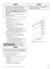
... original or photocopy of Emergency Release Cord. NOTE • Loosen (Do Not Remove) Terminal Block Screws. • Limit Switch adjustments and securing the Wires will be required. G Coil and bundle excess Limit Switch Wires on top of Power Head with Wire Clips (Figure 14). D Attach Emergency Release Tag to Magnetic Carriage Assembly Release Lever. 25 Emergency Release Tag Assembly Step C8H: RECORD OPENER MODEL AND SERIAL NUMBER Please note the following information so it is available...
... original or photocopy of Emergency Release Cord. NOTE • Loosen (Do Not Remove) Terminal Block Screws. • Limit Switch adjustments and securing the Wires will be required. G Coil and bundle excess Limit Switch Wires on top of Power Head with Wire Clips (Figure 14). D Attach Emergency Release Tag to Magnetic Carriage Assembly Release Lever. 25 Emergency Release Tag Assembly Step C8H: RECORD OPENER MODEL AND SERIAL NUMBER Please note the following information so it is available...

Owner's Manual
Page 18
... at Wall Console White Wire to Terminal "W" Striped Wire to wall near Wall Console. B Find a convenient mounting location: • Within direct sight of any moving garage door or Opener parts (you should not be sure to only tap them in as far as needed to Terminal "W". A Wall Console (Figure 31): • Has a Security Vacation Lock Switch which disables all controls. • LED Indicator shows whether system is powered, locked, or unlocked. F Remove protective...
... at Wall Console White Wire to Terminal "W" Striped Wire to wall near Wall Console. B Find a convenient mounting location: • Within direct sight of any moving garage door or Opener parts (you should not be sure to only tap them in as far as needed to Terminal "W". A Wall Console (Figure 31): • Has a Security Vacation Lock Switch which disables all controls. • LED Indicator shows whether system is powered, locked, or unlocked. F Remove protective...
Owner's Manual
Page 19
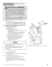
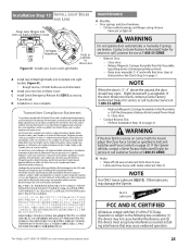
...; The Circuit Boards are not installing permanent wiring, go to install the proper outlet. D Perform Safe-T-Beam® alignment check: • Check if Safe-T-Beam® Source Red LED is glowing continuously (OK) or blinking (problem). • If Red LED is blinking twice, adjust Sensor Brackets as stated in any way. Four screws hold Motor Cover Figure 33 Connecting power with permanent wiring (Figure 33): • Remove power from circuit. • Remove Motor Cover. • Remove and discard Power Cord. - Replace Motor Cover. If the Plug does...
...; The Circuit Boards are not installing permanent wiring, go to install the proper outlet. D Perform Safe-T-Beam® alignment check: • Check if Safe-T-Beam® Source Red LED is glowing continuously (OK) or blinking (problem). • If Red LED is blinking twice, adjust Sensor Brackets as stated in any way. Four screws hold Motor Cover Figure 33 Connecting power with permanent wiring (Figure 33): • Remove power from circuit. • Remove Motor Cover. • Remove and discard Power Cord. - Replace Motor Cover. If the Plug does...
Owner's Manual
Page 20
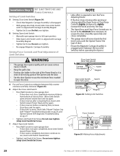
... Limit Switch same amount toward Power Head and try again. - If door reverses before operating the Opener. C Adjust Open Limit Switch: • Press Wall Console to move Limit Switch toward door. • Tighten Limit Switch Set Screw. If door opens completely, but motor continues to ensure the door smoothly opens fully and closes completely. • The garage door will move slowly the first time it is aligned with Carriage Assembly Magnet. • Tighten Set Screw. Installation SteCpH9: SET LIMIT SWITCHES AND FORCE CONTROLS Setting of Limit Switches A Setting Close Limit Switch...
... Limit Switch same amount toward Power Head and try again. - If door reverses before operating the Opener. C Adjust Open Limit Switch: • Press Wall Console to move Limit Switch toward door. • Tighten Limit Switch Set Screw. If door opens completely, but motor continues to ensure the door smoothly opens fully and closes completely. • The garage door will move slowly the first time it is aligned with Carriage Assembly Magnet. • Tighten Set Screw. Installation SteCpH9: SET LIMIT SWITCHES AND FORCE CONTROLS Setting of Limit Switches A Setting Close Limit Switch...
Owner's Manual
Page 21
... time. B Lay a 2" x 4" board flat in open garage door, and close . Do Not Unplug the Unit - If not, adjust Close Force Control slightly clockwise, open position using Wall Console. • Gently adjust Close Force fully counterclockwise (minimum force). • Run Opener using Wall Console. • Observe that door stops and reverses within 2 seconds after it again. • Repeat steps above until door reverses. • If door still does not reverse, move Limit Switch toward door. Installation SteCpH10: SETTING CONTACT REVERSE FUNCTION NOTE Limit Switch and Force Adjustments...
... time. B Lay a 2" x 4" board flat in open garage door, and close . Do Not Unplug the Unit - If not, adjust Close Force Control slightly clockwise, open position using Wall Console. • Gently adjust Close Force fully counterclockwise (minimum force). • Run Opener using Wall Console. • Observe that door stops and reverses within 2 seconds after it again. • Repeat steps above until door reverses. • If door still does not reverse, move Limit Switch toward door. Installation SteCpH10: SETTING CONTACT REVERSE FUNCTION NOTE Limit Switch and Force Adjustments...
Owner's Manual
Page 22
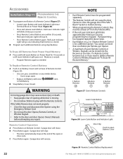
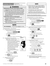
... 38 Learn Code Button and Indicator Light Model Number Visor Clip Push to play with new A23, 12 Volt Battery. To Erase All Remotes from the Antenna Wire. • If the red Learn Indicator Light blinks approximately 4 times per second. • Press Remote Control Button once within 30 seconds. You cannot use the door Opener, Remote Controls, or Wireless Keypad. • Refer to delete a Remote Control or Wireless Keypad, see "To Erase All Receiver Memory." Garage door will not cause the door Opener to close cycle. To Replace Remote Control Battery A Push...
... 38 Learn Code Button and Indicator Light Model Number Visor Clip Push to play with new A23, 12 Volt Battery. To Erase All Remotes from the Antenna Wire. • If the red Learn Indicator Light blinks approximately 4 times per second. • Press Remote Control Button once within 30 seconds. You cannot use the door Opener, Remote Controls, or Wireless Keypad. • Refer to delete a Remote Control or Wireless Keypad, see "To Erase All Receiver Memory." Garage door will not cause the door Opener to close cycle. To Replace Remote Control Battery A Push...
Owner's Manual
Page 23
... this door Opener ( or or ). - Red LED blinks - Red LED blinks several times and turns off . B Repeat step A above for 1 Door Opener A Set Wireless Keypad PIN (Personal ID Number): • Activate programming mode. - Program Keypad BEFORE mounting. If your PIN and press . - NOTE • If the door does not move the garage door: - Start over. C Programming Door Openers: • Decide which door will use door Opener, Remote Controls, or Wireless Keypad. 3 Refer to Door and Door Opener Owner's Manuals before attempting any repairs. Learn Code Indicator LED turns off...
... this door Opener ( or or ). - Red LED blinks - Red LED blinks several times and turns off . B Repeat step A above for 1 Door Opener A Set Wireless Keypad PIN (Personal ID Number): • Activate programming mode. - Program Keypad BEFORE mounting. If your PIN and press . - NOTE • If the door does not move the garage door: - Start over. C Programming Door Openers: • Decide which door will use door Opener, Remote Controls, or Wireless Keypad. 3 Refer to Door and Door Opener Owner's Manuals before attempting any repairs. Learn Code Indicator LED turns off...
Owner's Manual
Page 25
... Lens 1A Push in Latches to reverse on contact with Part 15 of Motor Cover MAINTENANCE A Monthly: • Door springs and door hardware: - Perform Installation Step 10 on page 3. Release Magnetic Carriage Assembly from Drive Screw. • Lubricate Drive Screw with Genie Lubricant (GLU-3) NOTE Use ONLY Genie Lubricant (GLU-3). WARNING If the door fails to close Lens Figure 41 Install Lens Cover and Light Bulbs A Install two 60 Watt light bulbs (not included) into slots in Set Limit Switches and Force Controls on...
... Lens 1A Push in Latches to reverse on contact with Part 15 of Motor Cover MAINTENANCE A Monthly: • Door springs and door hardware: - Perform Installation Step 10 on page 3. Release Magnetic Carriage Assembly from Drive Screw. • Lubricate Drive Screw with Genie Lubricant (GLU-3) NOTE Use ONLY Genie Lubricant (GLU-3). WARNING If the door fails to close Lens Figure 41 Install Lens Cover and Light Bulbs A Install two 60 Watt light bulbs (not included) into slots in Set Limit Switches and Force Controls on...
Owner's Manual
Page 26
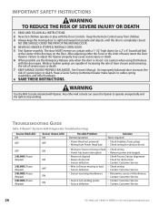
... A STOPPED, PARTIALLY OPEN DOOR. 5 Test Opener monthly. Use caution when using this Release with Opener. TROUBLESHOOTING GUIDE Safe-T-Beam® System Self-Diagnostic Troubleshooting Source (Red LED) ON OFF OFF 2 BLINKS, Pause (Repeat) 2 BLINKS, Pause (Repeat) 3 BLINKS, Pause (Repeat) 4 BLINKS, Pause (Repeat) Sensor (Green LED) ON OFF ON ON OFF ON ON Possible Problem Normal operation • Power Head not powered • Wiring from people and objects until the door is closed . The door MUST reverse on contact with the Door Controls. Have a Genie Factory...
... A STOPPED, PARTIALLY OPEN DOOR. 5 Test Opener monthly. Use caution when using this Release with Opener. TROUBLESHOOTING GUIDE Safe-T-Beam® System Self-Diagnostic Troubleshooting Source (Red LED) ON OFF OFF 2 BLINKS, Pause (Repeat) 2 BLINKS, Pause (Repeat) 3 BLINKS, Pause (Repeat) 4 BLINKS, Pause (Repeat) Sensor (Green LED) ON OFF ON ON OFF ON ON Possible Problem Normal operation • Power Head not powered • Wiring from people and objects until the door is closed . The door MUST reverse on contact with the Door Controls. Have a Genie Factory...

Owner's Manual
Page 27
... Safe-T-Beam® problems exists, the door can be installed and operational to enable door to Do • Reset Opener-unplug (or disconnect power), wait 5 seconds, plug back in (reapply power), and activate from Opener. Fuse on Motor Drive Board. - See door Safety Guide 1. See Door Safety Guide See page 16. See page 18 NOTE • The status LED Indicator Light is equipped with an automatic garage door balance detection system. Contact Customer Service for further assistance. Check Wall Console Wiring for...
... Safe-T-Beam® problems exists, the door can be installed and operational to enable door to Do • Reset Opener-unplug (or disconnect power), wait 5 seconds, plug back in (reapply power), and activate from Opener. Fuse on Motor Drive Board. - See door Safety Guide 1. See Door Safety Guide See page 16. See page 18 NOTE • The status LED Indicator Light is equipped with an automatic garage door balance detection system. Contact Customer Service for further assistance. Check Wall Console Wiring for...
Owner's Manual
Page 28
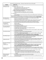
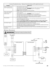
... Status LED Light) Problem What To Do Opener does not run closed • Check Wires to ensure that they are not cut insulation and short Wires). Replace as needed . - Adjust as needed . • Check for shorted Wires. • Check garage door for binding. • If a new installation, check Door Arm position. • Check operation of Contact Reverse function. • Check Safe-T-Beam® System for proper wiring. • Check Open Force adjustment (see Set Limit Switches and Force Controls...
... Status LED Light) Problem What To Do Opener does not run closed • Check Wires to ensure that they are not cut insulation and short Wires). Replace as needed . - Adjust as needed . • Check for shorted Wires. • Check garage door for binding. • If a new installation, check Door Arm position. • Check operation of Contact Reverse function. • Check Safe-T-Beam® System for proper wiring. • Check Open Force adjustment (see Set Limit Switches and Force Controls...
Owner's Manual
Page 29
... diagnostic codes. If present, troubleshoot as detailed in Safe-T-Beam® System Self-Diagnostic Troubleshooting Chart (See page 26). General Troubleshooting (Always Check the Status LED Light)(Continued) Problem What To Do Remote Control has less than 25' operating range Opener works from Wall Control, but not from Remote Control • Relocate Remote Control inside car. • Ensure Remote Control is pointing toward garage door when pressing Control Button. • Replace Remote Control Battery type "A23." (See page 22). • Reposition Opener Antenna Wire...
... diagnostic codes. If present, troubleshoot as detailed in Safe-T-Beam® System Self-Diagnostic Troubleshooting Chart (See page 26). General Troubleshooting (Always Check the Status LED Light)(Continued) Problem What To Do Remote Control has less than 25' operating range Opener works from Wall Control, but not from Remote Control • Relocate Remote Control inside car. • Ensure Remote Control is pointing toward garage door when pressing Control Button. • Replace Remote Control Battery type "A23." (See page 22). • Reposition Opener Antenna Wire...
Owner's Manual
Page 30
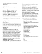
... Series - ISD990-2 Series - ISD995 Series - CMD9900 Series - How to Genie products purchased in accordance with the product • Programming of Remote Control Devices • Programming of Keypads • Safe-T-Beam® adjustment/cleaning • Staples through wiring • Pinched or broken wires • Carriage disengaged • Force Control adjustments • Door out of balance • Broken springs or cables • Power outages • Use of extension cords • Missing or damaged parts on parts and service. Service From...
... Series - ISD990-2 Series - ISD995 Series - CMD9900 Series - How to Genie products purchased in accordance with the product • Programming of Remote Control Devices • Programming of Keypads • Safe-T-Beam® adjustment/cleaning • Staples through wiring • Pinched or broken wires • Carriage disengaged • Force Control adjustments • Door out of balance • Broken springs or cables • Power outages • Use of extension cords • Missing or damaged parts on parts and service. Service From...


