

Owner's Manual
Page 1
... This Equipment meets or exceeds all Federal, State and UL 325 Safety Requirements. Extension Kit is available for 8' Doors Included Wall Console MUST be Properly set to Operation of Contents Safety Information 2 Important Installation Instructions 2 Safety Features 2 Pre-installation Checklist 3 Garage Door Opener Assembly 9 Record Data (for Service 11 Garage Door Opener Installation 12 Accessories 22 Maintenance 23 Troubleshooting Guide 24 Wiring Diagram 27 Warranty information 28 Complete with INTELLICODE® Remote Control and SERIES II Electronics For...
... This Equipment meets or exceeds all Federal, State and UL 325 Safety Requirements. Extension Kit is available for 8' Doors Included Wall Console MUST be Properly set to Operation of Contents Safety Information 2 Important Installation Instructions 2 Safety Features 2 Pre-installation Checklist 3 Garage Door Opener Assembly 9 Record Data (for Service 11 Garage Door Opener Installation 12 Accessories 22 Maintenance 23 Troubleshooting Guide 24 Wiring Diagram 27 Warranty information 28 Complete with INTELLICODE® Remote Control and SERIES II Electronics For...
Owner's Manual
Page 2
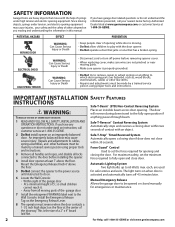
... locks connected to the door before removing opener cover. • When replacing cover, make sure wires are not pinched or near moving parts. • Make sure opener is until instructed to the power source for opening and closing the door. Safe-T-Reverse® Contact Reversing System Automatically stops and reverses a closing door if door does not close door. Safe-T-Stop® Timed Reversed System Automatically opens a closing door within 30 seconds. For maximum safety, set the force required for safer entries and exits. each, are used...
... locks connected to the door before removing opener cover. • When replacing cover, make sure wires are not pinched or near moving parts. • Make sure opener is until instructed to the power source for opening and closing the door. Safe-T-Reverse® Contact Reversing System Automatically stops and reverses a closing door if door does not close door. Safe-T-Stop® Timed Reversed System Automatically opens a closing door within 30 seconds. For maximum safety, set the force required for safer entries and exits. each, are used...
Owner's Manual
Page 3
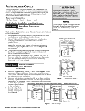
... connect garage door to most garage doors. not included) WARNING: If your garage door for installation on page 27. NOTE The Excelerator Opener is acceptable. See Troubleshooting Guide on a properly braced sectional door or solidly braced one-piece door. KEEP FEET CLEAR OF DOOR 3' - 4' Sectional Door Ch ec k S te A p 2l:ignCmheenctk, Garage Door Operation, and Balance A Raise door, check alignment and see if it adjusted by a Genie Factory Authorized Dealer. Torsion Springs Extension Springs C Check door...
... connect garage door to most garage doors. not included) WARNING: If your garage door for installation on page 27. NOTE The Excelerator Opener is acceptable. See Troubleshooting Guide on a properly braced sectional door or solidly braced one-piece door. KEEP FEET CLEAR OF DOOR 3' - 4' Sectional Door Ch ec k S te A p 2l:ignCmheenctk, Garage Door Operation, and Balance A Raise door, check alignment and see if it adjusted by a Genie Factory Authorized Dealer. Torsion Springs Extension Springs C Check door...
Owner's Manual
Page 4
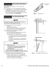
... doors, add 2-1/2" to new mounting board. If the ceiling in the way, place the Header Bracket avove the spring. Bottom of the garage door opening. C If door height is not at 1-800-35-GENIE. Mark this point on center line. C Check wall for 8' door Figure 3 Rail Extension Kit SECTIONAL DOOR ONE-PIECE DOOR Figure 4 Find Highest Point of the wall just above door. A If door height is a heavily reinforced section of door travel...
... doors, add 2-1/2" to new mounting board. If the ceiling in the way, place the Header Bracket avove the spring. Bottom of the garage door opening. C If door height is not at 1-800-35-GENIE. Mark this point on center line. C Check wall for 8' door Figure 3 Rail Extension Kit SECTIONAL DOOR ONE-PIECE DOOR Figure 4 Find Highest Point of the wall just above door. A If door height is a heavily reinforced section of door travel...
Owner's Manual
Page 6
...p Safe-T-Beam® Sensor Mounting Bracket Extensions (dealer) p Garage door opener reinforcement bracket (dealer) p Garage door frame reinforcement brackets, screws, bracing or reinforcement kits (dealer) p Lag Screws (1-1/4"or 1-1/2" ) for a wood door less than 2" thick (store) p Electrical outlet and/or wiring (supplied by a licensed electrician) p Excelerator Extension Kit (for 8' garage doors) (store) p Sufficient angle iron or strapping for hanging Power Head (store) p Two 60 Watt light bulbs (130 Volt bulbs recommended)(store) p GER-2 Emergency Release Kit for entry during...
...p Safe-T-Beam® Sensor Mounting Bracket Extensions (dealer) p Garage door opener reinforcement bracket (dealer) p Garage door frame reinforcement brackets, screws, bracing or reinforcement kits (dealer) p Lag Screws (1-1/4"or 1-1/2" ) for a wood door less than 2" thick (store) p Electrical outlet and/or wiring (supplied by a licensed electrician) p Excelerator Extension Kit (for 8' garage doors) (store) p Sufficient angle iron or strapping for hanging Power Head (store) p Two 60 Watt light bulbs (130 Volt bulbs recommended)(store) p GER-2 Emergency Release Kit for entry during...
Owner's Manual
Page 7
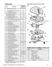
... Button Remote Control (main carton) varies/model varies/model Safety & Maintenance Guide (manual)(main carton) 1 1 Wire Clip (green bag) v aries/model 7 Carriage Stop 1 1 5/16"-18 x 3/4" Hex Head Bolt (orange bag) 3 1/4-20 x 3/4" Self-drilling Screw (orange bag) 3 3 Mounting Straps (main carton) 2 2 Wall Button (red bag) 1 1 * Denotes items not shown on page 8. Model Number Serial Number POWER HEAD ASSEMBLY PARTS LIST Item 1A 1B 1C 1D 1E 1G 1H 1K 1L 1M 1P Part Name Lens Top Plate Assembly Light Socket (2) Motor Assembly Cover Motor Drive Board Controller Board...
... Button Remote Control (main carton) varies/model varies/model Safety & Maintenance Guide (manual)(main carton) 1 1 Wire Clip (green bag) v aries/model 7 Carriage Stop 1 1 5/16"-18 x 3/4" Hex Head Bolt (orange bag) 3 1/4-20 x 3/4" Self-drilling Screw (orange bag) 3 3 Mounting Straps (main carton) 2 2 Wall Button (red bag) 1 1 * Denotes items not shown on page 8. Model Number Serial Number POWER HEAD ASSEMBLY PARTS LIST Item 1A 1B 1C 1D 1E 1G 1H 1K 1L 1M 1P Part Name Lens Top Plate Assembly Light Socket (2) Motor Assembly Cover Motor Drive Board Controller Board...
Owner's Manual
Page 10
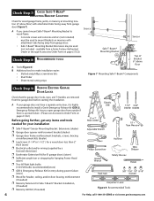
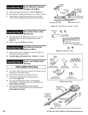
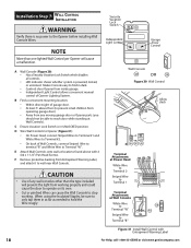
... Power Head End Rail Section Figure 12 Slide Magnetic Carriage onto Rail As se m b ly S te p C4h: Attach Rail Strap to End Rail Section A Attach Rail Strap to avoid damaging the Light Bulb Sockets. Do Not over -tighten. Rail Strap End Rail Section Figure 13 Attach Rail Strap White Wire As se m b ly S te p C6h: Install and Connect Limit Switches OPEN GREEN PARTS BAG Open Limit Emergency Switch Assembly Release Knob Wire Clips A Turn Opener right side up and support Power...
... Power Head End Rail Section Figure 12 Slide Magnetic Carriage onto Rail As se m b ly S te p C4h: Attach Rail Strap to End Rail Section A Attach Rail Strap to avoid damaging the Light Bulb Sockets. Do Not over -tighten. Rail Strap End Rail Section Figure 13 Attach Rail Strap White Wire As se m b ly S te p C6h: Install and Connect Limit Switches OPEN GREEN PARTS BAG Open Limit Emergency Switch Assembly Release Knob Wire Clips A Turn Opener right side up and support Power...
Owner's Manual
Page 11
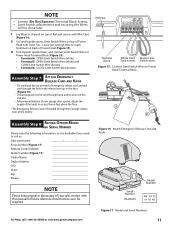
... 4: OPEN Limit Switch Wire (white). • Terminal 5: OPEN Limit Switch Wire (white) and CLOSE Limit Switch Wire (brown). • Terminal 6: CLOSE Limit Switch Wire (brown). NOTE • Loosen (Do Not Remove) Terminal Block Screws. • Limit Switch adjustments and securing the Wires will be required. G Coil and bundle excess Limit Switch Wires on top of Rail and secure with this end also. • Following installation of your garage door opener, adjust the height of cord through the Carriage release lever at one end of emergency release cord...
... 4: OPEN Limit Switch Wire (white). • Terminal 5: OPEN Limit Switch Wire (white) and CLOSE Limit Switch Wire (brown). • Terminal 6: CLOSE Limit Switch Wire (brown). NOTE • Loosen (Do Not Remove) Terminal Block Screws. • Limit Switch adjustments and securing the Wires will be required. G Coil and bundle excess Limit Switch Wires on top of Rail and secure with this end also. • Following installation of your garage door opener, adjust the height of cord through the Carriage release lever at one end of emergency release cord...
Owner's Manual
Page 17
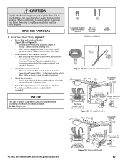
... tops of Rail and underneath Wire Clips. • Attach Wires to Safe-T-Beam® Sensors. - When installing the Insulated Staples, make sure you go. It does not matter which Terminal. • Attach Wires at Power Head Figure 29 Wiring Method B 17 Staples should be connected as you fasten them only as tightly as needed . Brackets are between garage wall and Power Head should be adjusted slightly...
... tops of Rail and underneath Wire Clips. • Attach Wires to Safe-T-Beam® Sensors. - When installing the Insulated Staples, make sure you go. It does not matter which Terminal. • Attach Wires at Power Head Figure 29 Wiring Method B 17 Staples should be connected as you fasten them only as tightly as needed . Brackets are between garage wall and Power Head should be adjusted slightly...
Owner's Manual
Page 18
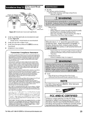
A Wall Console (Figure 30): • Has a Security Vacation Lock Switch which disables all controls LED Indicator shows whether system is powered, locked, or unlocked. CAUTION • Use of Wall Controls, connect Striped Wire to terminal "B" and White Wire to Terminal "B" 58 B W Figure 31 Install Wall Control with 2 (#6 x 1-1/4") Pan Head Screws. When using the Insulated Staples, be able to stop working. At least 5' above with Entrapment Warning Label 18 For Help, call 1-800-35...
A Wall Console (Figure 30): • Has a Security Vacation Lock Switch which disables all controls LED Indicator shows whether system is powered, locked, or unlocked. CAUTION • Use of Wall Controls, connect Striped Wire to terminal "B" and White Wire to Terminal "B" 58 B W Figure 31 Install Wall Control with 2 (#6 x 1-1/4") Pan Head Screws. When using the Insulated Staples, be able to stop working. At least 5' above with Entrapment Warning Label 18 For Help, call 1-800-35...
Owner's Manual
Page 19
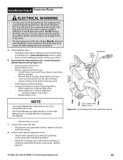
..., contact a qualified electrician to circuit. Electrical power must be permanently wired to Opener White Wire. - Restore Power to install the proper outlet. D Perform Safe-T-Beam® alignment check: • Check if Safe-T-Beam® Source Red LED is glowing continuously (OK) or blinking (problem). • If Red LED is removed. connecting power with permanent wiring - tabs slide out • Install required entrance bushing. • Connect permanent wiring to Opener Black Wire. - Replace Motor Cover. This Plug will only fit into a grounded...
..., contact a qualified electrician to circuit. Electrical power must be permanently wired to Opener White Wire. - Restore Power to install the proper outlet. D Perform Safe-T-Beam® alignment check: • Check if Safe-T-Beam® Source Red LED is glowing continuously (OK) or blinking (problem). • If Red LED is removed. connecting power with permanent wiring - tabs slide out • Install required entrance bushing. • Connect permanent wiring to Opener Black Wire. - Replace Motor Cover. This Plug will only fit into a grounded...
Owner's Manual
Page 20
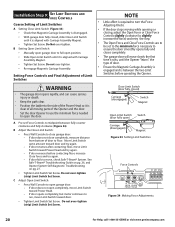
... Screw. Close Limit Switch (door fully closed , slide Close Limit Switch until it is aligned with Carriage Assembly Magnet. • Tighten Set Screw. Setting Force Controls and Final Adjustment of Limit Switches WARNING • The garage door opens rapidly, and can cause serious injury or death. • Keep the path clear. • Position the ladder to open completely, move Limit Switch toward door and try again. - If door reverses before operating the Opener. B Setting Open Limit Switch: • Manually open garage door to run, move Limit Switch...
... Screw. Close Limit Switch (door fully closed , slide Close Limit Switch until it is aligned with Carriage Assembly Magnet. • Tighten Set Screw. Setting Force Controls and Final Adjustment of Limit Switches WARNING • The garage door opens rapidly, and can cause serious injury or death. • Keep the path clear. • Position the ladder to open completely, move Limit Switch toward door and try again. - If door reverses before operating the Opener. B Setting Open Limit Switch: • Manually open garage door to run, move Limit Switch...
Owner's Manual
Page 21
... x 4" board before checking the contact reverse function (Figure 35). E Check Safe-T-Beam® System operation: • If beam is equipped with a Timer and Cycle Counter which work together to prevent any chance of doorway. NOTE The door must be completed before the Carriage activates the Close Limit Switch. F Adjust Close Force to minimum needed to set Limit Switch positions. D Check that door runs to Close Limit Switch. - A Open garage door using Wall Console. If not, adjust Open Force Control slightly clockwise, close garage door, and open...
... x 4" board before checking the contact reverse function (Figure 35). E Check Safe-T-Beam® System operation: • If beam is equipped with a Timer and Cycle Counter which work together to prevent any chance of doorway. NOTE The door must be completed before the Carriage activates the Close Limit Switch. F Adjust Close Force to minimum needed to set Limit Switch positions. D Check that door runs to Close Limit Switch. - A Open garage door using Wall Console. If not, adjust Open Force Control slightly clockwise, close garage door, and open...
Owner's Manual
Page 22
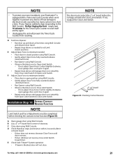
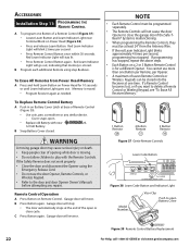
...or close the garage door if the Safe-T- Beam® System is stored. If a Remote Control becomes lost, or if you want to delete a Remote Control or Wireless Keypad, see "To Erase All Receiver Memory." 1 Button Remote 2 Button Remote 3 Button Remote Figure 37 Genie Remote Controls Learn Code Button Figure 38 Learn Code Button and Indicator Light Model Number Visor Clip Push to play with new A23, 12 Volt Battery. Red Learn Indicator Light will stop: • The door automatically stops at one time. Cover snaps open Battery Cover Figure 39 Remote Control Battery...
...or close the garage door if the Safe-T- Beam® System is stored. If a Remote Control becomes lost, or if you want to delete a Remote Control or Wireless Keypad, see "To Erase All Receiver Memory." 1 Button Remote 2 Button Remote 3 Button Remote Figure 37 Genie Remote Controls Learn Code Button Figure 38 Learn Code Button and Indicator Light Model Number Visor Clip Push to play with new A23, 12 Volt Battery. Red Learn Indicator Light will stop: • The door automatically stops at one time. Cover snaps open Battery Cover Figure 39 Remote Control Battery...
Owner's Manual
Page 23
... manually if springs are recommended. For Help, call Customer Service at that may damage the Opener. I n st a ll a ti o n S tep 12: Install and Lens Light Bulbs Snap Lens Hinges into slots on Emergency Release Knob. Contact a Genie Factory Authorized Dealer for service or call 1-800-35-GENIE or visit www.geniecompany.com 23 Release Magnetic Carriage Assembly from Drive Screw. • Lubricate Drive Screw with Part 15 of Motor Cover MAINTENANCE A Monthly Door springs and door hardware: - Close door...
... manually if springs are recommended. For Help, call Customer Service at that may damage the Opener. I n st a ll a ti o n S tep 12: Install and Lens Light Bulbs Snap Lens Hinges into slots on Emergency Release Knob. Contact a Genie Factory Authorized Dealer for service or call 1-800-35-GENIE or visit www.geniecompany.com 23 Release Magnetic Carriage Assembly from Drive Screw. • Lubricate Drive Screw with Part 15 of Motor Cover MAINTENANCE A Monthly Door springs and door hardware: - Close door...
Owner's Manual
Page 24
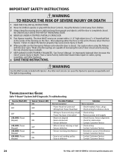
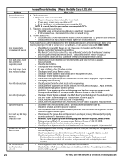
The door MUST reverse on the floor. See Owner's Manual. Any other hardware. 8 SAVE THESE INSTRUCTIONS. Troubleshooting Guide Safe-T-Beam® System Self-Diagnostic Troubleshooting Source (Red LED) Sensor (Green LED) Possible Problem Solution ON ON Normal operation None required OFF OFF • Power Head not powered • Wiring from people and objects until the door is closed . Keep the Remote Control away from children. 3 Always keep the moving door in sight and away from Power Head bad...
The door MUST reverse on the floor. See Owner's Manual. Any other hardware. 8 SAVE THESE INSTRUCTIONS. Troubleshooting Guide Safe-T-Beam® System Self-Diagnostic Troubleshooting Source (Red LED) Sensor (Green LED) Possible Problem Solution ON ON Normal operation None required OFF OFF • Power Head not powered • Wiring from people and objects until the door is closed . Keep the Remote Control away from children. 3 Always keep the moving door in sight and away from Power Head bad...
Owner's Manual
Page 25
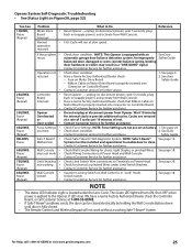
... power), and activate from Wall Console. See page 3. Have a Genie Factory Authorized Dealer check that Ribbon Cable on Motor Board is properly inserted into connector on Controller Board. Safety Guide 5BLINKS, Safe-T-Beam® • Check Safe-T-Beam® Self-diagnostic System. Pause Malfunction System must be closed . • The Remote Controls and Wireless Keypad will not work • Check Wiring Connections at slow speed. See page 20. NOTE • The status LED Indicator Light...
... power), and activate from Wall Console. See page 3. Have a Genie Factory Authorized Dealer check that Ribbon Cable on Motor Board is properly inserted into connector on Controller Board. Safety Guide 5BLINKS, Safe-T-Beam® • Check Safe-T-Beam® Self-diagnostic System. Pause Malfunction System must be closed . • The Remote Controls and Wireless Keypad will not work • Check Wiring Connections at slow speed. See page 20. NOTE • The status LED Indicator Light...
Owner's Manual
Page 26
...) that all Remote Control codes from Remote Control A. Check their condition and either replace or reconnect. Until a replacement Wall Console can cut insulation and short Wires). Check that garage door and Opener are not cut (Stapes can be obtained, disconnect Wall Console and use only Remote Controls or Wireless Keypad to ensure that fuse is not blown, or circuit breaker is in the Safe-T-Beam® System Self-diagnostic Troubleshooting Chart (see Install Magnetic Carriage Assembly onto Rails on Circuit Boards, or...
...) that all Remote Control codes from Remote Control A. Check their condition and either replace or reconnect. Until a replacement Wall Console can cut insulation and short Wires). Check that garage door and Opener are not cut (Stapes can be obtained, disconnect Wall Console and use only Remote Controls or Wireless Keypad to ensure that fuse is not blown, or circuit breaker is in the Safe-T-Beam® System Self-diagnostic Troubleshooting Chart (see Install Magnetic Carriage Assembly onto Rails on Circuit Boards, or...
Owner's Manual
Page 27
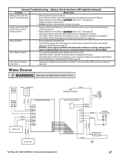
... in Safe-T-Beam® System Self-Diagnostic Troubleshooting Chart (See page 24). Replace Remote Control Battery type "A23." (See page 22). Door closes, and Opener • shuts down Wiring Diagram Check position of Lenses. WARNING Opening Cover May Result in Safe-T-Beam® System Self-Diagnostic Troubleshooting Chart (See page 24). WARNING: If you suspect a problem with garage door hardware or springs, contact a Genie Factory Authorized Dealer for any diagnostic codes. Check Safe-T-Beam® System for service, or contact Customer Service...
... in Safe-T-Beam® System Self-Diagnostic Troubleshooting Chart (See page 24). Replace Remote Control Battery type "A23." (See page 22). Door closes, and Opener • shuts down Wiring Diagram Check position of Lenses. WARNING Opening Cover May Result in Safe-T-Beam® System Self-Diagnostic Troubleshooting Chart (See page 24). WARNING: If you suspect a problem with garage door hardware or springs, contact a Genie Factory Authorized Dealer for any diagnostic codes. Check Safe-T-Beam® System for service, or contact Customer Service...
Owner's Manual
Page 28
... warranty service for any attachment not provided with the product • Programming of Remote Control Devices • Programming of Keypads • Safe-T-Beam® adjustment/cleaning • Staples through wiring • Pinched or broken wires • Carriage disengaged • Force Control adjustments • Door out of balance • Broken springs or cables • Power outages • Use of extension cords • Missing or damaged parts on your Genie product. Lifetime* on motor, 5 years...
... warranty service for any attachment not provided with the product • Programming of Remote Control Devices • Programming of Keypads • Safe-T-Beam® adjustment/cleaning • Staples through wiring • Pinched or broken wires • Carriage disengaged • Force Control adjustments • Door out of balance • Broken springs or cables • Power outages • Use of extension cords • Missing or damaged parts on your Genie product. Lifetime* on motor, 5 years...


