

Owner's Manual
Page 2
... to do not understand the information presented, call your service representative. 2 Do Not install operator on the floor at 1-800-35-GENIE.. POTENTIAL HAZARD EFFECT PREVENTION MOVING DOOR WARNING: Can Cause Serious Injury or Death • Keep people clear of opening while door is...of 5 feet, so small children cannot reach it. • Away from all moving parts. • Operator must be opened or closed manually for emergencies or maintenance. 2 For Help, call your nearest Genie Factory Authorized Dealer listed at www.geniecompany.com, or customer Service at the center of...
... to do not understand the information presented, call your service representative. 2 Do Not install operator on the floor at 1-800-35-GENIE.. POTENTIAL HAZARD EFFECT PREVENTION MOVING DOOR WARNING: Can Cause Serious Injury or Death • Keep people clear of opening while door is...of 5 feet, so small children cannot reach it. • Away from all moving parts. • Operator must be opened or closed manually for emergencies or maintenance. 2 For Help, call your nearest Genie Factory Authorized Dealer listed at www.geniecompany.com, or customer Service at the center of...
Owner's Manual
Page 3
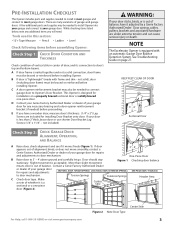
... DOOR, EXTENSION SPRINGS ONE-PIECE DOOR, TRACKLESS to door mechanism. D Contact your Genie Factory Authorized Dealer or dealer of your door is less than slight movement Figure 1... Checking door balance means door is equipped with frame and skin - NOTE The Excelerator Opener is out of whether it moves freely (Figure 1). This Opener is out of door...Raise door, check alignment and see if it is acceptable. PRE-INSTALLATION CHECKLIST This Opener includes parts and supplies needed to install in most garage doors. C A door opener reinforcement bracket may ...
... DOOR, EXTENSION SPRINGS ONE-PIECE DOOR, TRACKLESS to door mechanism. D Contact your Genie Factory Authorized Dealer or dealer of your door is less than slight movement Figure 1... Checking door balance means door is equipped with frame and skin - NOTE The Excelerator Opener is out of whether it moves freely (Figure 1). This Opener is out of door...Raise door, check alignment and see if it is acceptable. PRE-INSTALLATION CHECKLIST This Opener includes parts and supplies needed to install in most garage doors. C A door opener reinforcement bracket may ...

Owner's Manual
Page 7
... 1L Model Number Serial Number 1M 1H 1P POWER HEAD ASSEMBLY PARTS LIST Item 1A 1B 1C 1D 1E 1G 1H 1K 1L 1M 1P Part Name Lens Top Plate Assembly Light Socket (2) Motor Assembly Cover ...32 x 1" Phillips Screw No. 8-32 x 3/8" Slotted Hex Head Screw Power Cord For Help, call 1-800-35-GENIE or visit www.geniecompany.com 7 Parts List Item 1 2 3 4 4A 4B 4C 8 9 10 11 12 13 14 15 16 18 19 21 22 ...38* 40* 41* 42* 43* 44* 45* 46 47* 48* 49* 50* 51* 52* 53 54 55* 56 57 Part Name Quantity Required 1-Pc Rail 3-Pc Rail Power Head Assembly (main carton) 1 1 1/4"-20 x 13/16" Hex Head Shoulder Bolt ...
... 1L Model Number Serial Number 1M 1H 1P POWER HEAD ASSEMBLY PARTS LIST Item 1A 1B 1C 1D 1E 1G 1H 1K 1L 1M 1P Part Name Lens Top Plate Assembly Light Socket (2) Motor Assembly Cover ...32 x 1" Phillips Screw No. 8-32 x 3/8" Slotted Hex Head Screw Power Cord For Help, call 1-800-35-GENIE or visit www.geniecompany.com 7 Parts List Item 1 2 3 4 4A 4B 4C 8 9 10 11 12 13 14 15 16 18 19 21 22 ...38* 40* 41* 42* 43* 44* 45* 46 47* 48* 49* 50* 51* 52* 53 54 55* 56 57 Part Name Quantity Required 1-Pc Rail 3-Pc Rail Power Head Assembly (main carton) 1 1 1/4"-20 x 13/16" Hex Head Shoulder Bolt ...
Owner's Manual
Page 9
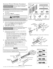
...Finger-tighten until later. (Middle Rail Section looks the same on Retaining Clip 10 Figure 11 Attach Middle Rail Section For Help, call 1-800-35-GENIE or visit www.geniecompany.com 9 Assembly Step C2H: INSTALL REMAINING RAIL SECTIONS A Arrange arrows on Rail Sections to point in step A & B....Install Coupler on collar 11B. Slip on Motor Shaft (Figure 9). GARAGE DOOR OPENER ASSEMBLY Assembly Step C1H: CONNECT RAIL TO POWER HEAD OPEN BLUE PARTS BAG A Turn Power Head upside down and place on Drive Screw next to Collar (Figure11D). Slide Collar over them (Figure 11B) and (Figure ...
...Finger-tighten until later. (Middle Rail Section looks the same on Retaining Clip 10 Figure 11 Attach Middle Rail Section For Help, call 1-800-35-GENIE or visit www.geniecompany.com 9 Assembly Step C2H: INSTALL REMAINING RAIL SECTIONS A Arrange arrows on Rail Sections to point in step A & B....Install Coupler on collar 11B. Slip on Motor Shaft (Figure 9). GARAGE DOOR OPENER ASSEMBLY Assembly Step C1H: CONNECT RAIL TO POWER HEAD OPEN BLUE PARTS BAG A Turn Power Head upside down and place on Drive Screw next to Collar (Figure11D). Slide Collar over them (Figure 11B) and (Figure ...

Owner's Manual
Page 10
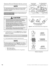
...Figure 14). End Rail Section 4C 8 Figure 13 Attach Rail Strap White Wire 21 Assembly Step C6H: INSTALL AND CONNECT LIMIT SWITCHES OPEN GREEN PARTS BAG A Turn Opener right side up and support Power Head to End Rail Section with arrows pointing away from the Power Head (Figure 12).... B Tighten snugly but Do Not over -tighten. Insert (#8-32 x 1") Hex Head Screw into slot on Assembled Rail 10 For Help, call 1-800-35-GENIE or visit www.geniecompany.com B Securely tighten all Rail Sections so Magnetic Carriage Assembly can slide freely along length of Rail. B Uncoil Limit Switch Wires...
...Figure 14). End Rail Section 4C 8 Figure 13 Attach Rail Strap White Wire 21 Assembly Step C6H: INSTALL AND CONNECT LIMIT SWITCHES OPEN GREEN PARTS BAG A Turn Opener right side up and support Power Head to End Rail Section with arrows pointing away from the Power Head (Figure 12).... B Tighten snugly but Do Not over -tighten. Insert (#8-32 x 1") Hex Head Screw into slot on Assembled Rail 10 For Help, call 1-800-35-GENIE or visit www.geniecompany.com B Securely tighten all Rail Sections so Magnetic Carriage Assembly can slide freely along length of Rail. B Uncoil Limit Switch Wires...
Owner's Manual
Page 12
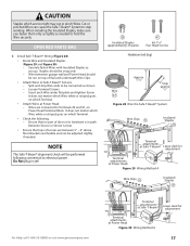
...5/16-18 x 3/4" Hex Serrated Flange Nuts 28 Door Bracket 56 1/4"-20 x 3/4" Self-Drilling Screws Hardware (orange bag) 12 For Help, call 1-800-35-GENIE or visit www.geniecompany.com Alternative Header Bracket orientations Highest Point of the door. • Mark 3 hole positions. • Drill 3 (5/32") pilot holes. &#... can then be necessary to attach a 2" x 6" board across the wall studs above the door header to the garage framing. OPEN ORANGE PARTS BAG B Attach Header Bracket to header at least two (four is critical that the point where the Rail attaches to the Header Bracket be ...
...5/16-18 x 3/4" Hex Serrated Flange Nuts 28 Door Bracket 56 1/4"-20 x 3/4" Self-Drilling Screws Hardware (orange bag) 12 For Help, call 1-800-35-GENIE or visit www.geniecompany.com Alternative Header Bracket orientations Highest Point of the door. • Mark 3 hole positions. • Drill 3 (5/32") pilot holes. &#... can then be necessary to attach a 2" x 6" board across the wall studs above the door header to the garage framing. OPEN ORANGE PARTS BAG B Attach Header Bracket to header at least two (four is critical that the point where the Rail attaches to the Header Bracket be ...

Owner's Manual
Page 15
... Curved 36 34 Door Arm 31 Straight Door Arm 33 For Help, call 1-800-35-GENIE or visit www.geniecompany.com Figure 24 Assemble Arms (ONE-PIECE) 15 Installation SteCpH5: ASSEMBLE AND CONNECT DOOR ARMS OPEN YELLOW PARTS BAG For sectional doors: A Attach Curved Door Arm to Door Bracket with Clevis Pin...
... Curved 36 34 Door Arm 31 Straight Door Arm 33 For Help, call 1-800-35-GENIE or visit www.geniecompany.com Figure 24 Assemble Arms (ONE-PIECE) 15 Installation SteCpH5: ASSEMBLE AND CONNECT DOOR ARMS OPEN YELLOW PARTS BAG For sectional doors: A Attach Curved Door Arm to Door Bracket with Clevis Pin...
Owner's Manual
Page 17
...slack for adjustment Terminal attachments at Power Head Figure 29 Wiring Method A Wire Clips 53 Insulated Staples 38 For Help, call 1-800-35-GENIE or visit www.geniecompany.com 654321 STB Terminal attachments at Safe-T-Beam® Terminal attachments at Power Head. - When installing the Insulated ... and Figure 30). - Wires between 5" - 6" above floor. Do Not plug in path between Source or Sensor Lenses. • Ensure that no part of Lenses are connected to Terminals #2 and #3 on which Terminal. • Attach Wires at Power Head Figure 30 Wiring Method A Leave slack for ...
...slack for adjustment Terminal attachments at Power Head Figure 29 Wiring Method A Wire Clips 53 Insulated Staples 38 For Help, call 1-800-35-GENIE or visit www.geniecompany.com 654321 STB Terminal attachments at Safe-T-Beam® Terminal attachments at Power Head. - When installing the Insulated ... and Figure 30). - Wires between 5" - 6" above floor. Do Not plug in path between Source or Sensor Lenses. • Ensure that no part of Lenses are connected to Terminals #2 and #3 on which Terminal. • Attach Wires at Power Head Figure 30 Wiring Method A Leave slack for ...

Owner's Manual
Page 18
...direct sight of any wall consoles other than one lighted Wall Control per Opener will prevent the light from any moving garage door or Opener parts (you should not be sure to only tap them in as far as needed to Terminal "B" 654321 PB/WC Figure 32 Install Wall Console... standing at Wall Console). CAUTION • Use of garage door. • At least 5' above with Entrapment Warning Label 18 For Help, call 1-800-35-GENIE or visit www.geniecompany.com When using the Insulated Staples, be able to stop working. A Wall Console (Figure 31): • Has a Security Vacation Lock ...
...direct sight of any wall consoles other than one lighted Wall Control per Opener will prevent the light from any moving garage door or Opener parts (you should not be sure to only tap them in as far as needed to Terminal "B" 654321 PB/WC Figure 32 Install Wall Console... standing at Wall Console). CAUTION • Use of garage door. • At least 5' above with Entrapment Warning Label 18 For Help, call 1-800-35-GENIE or visit www.geniecompany.com When using the Insulated Staples, be able to stop working. A Wall Console (Figure 31): • Has a Security Vacation Lock ...
Owner's Manual
Page 20
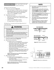
... 34 Setting Limit Switches Force Controls HI LO HI LO OPEN CLOSE FORCE FORCE Figure 35 Making Force Adjustments 20 For Help, call 1-800-35-GENIE or visit www.geniecompany.com Do Not over -tighten. • Re-engage Magnetic Carriage Assembly. Move Limit Switch same amount toward Power Head and try... door. • Tighten Limit Switch Set Screw. NOTE • Little effort is required to turn the Force Adjusting Knobs. • If the door stops moving parts of the Opener and the door. • Set the door Opener to use the minimum force needed to move slowly the first time it is...
... 34 Setting Limit Switches Force Controls HI LO HI LO OPEN CLOSE FORCE FORCE Figure 35 Making Force Adjustments 20 For Help, call 1-800-35-GENIE or visit www.geniecompany.com Do Not over -tighten. • Re-engage Magnetic Carriage Assembly. Move Limit Switch same amount toward Power Head and try... door. • Tighten Limit Switch Set Screw. NOTE • Little effort is required to turn the Force Adjusting Knobs. • If the door stops moving parts of the Opener and the door. • Set the door Opener to use the minimum force needed to move slowly the first time it is...
Owner's Manual
Page 23
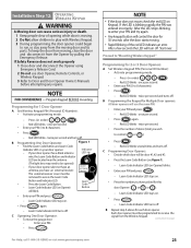
...Not allow children to play with Wireless Keypad. 3 During programming, the door opener could begin to receive the signal from moving door and its parts. Red LED blinks - Red LED blinks - If Safety Reverse does not work properly 1 Close door and disconnect the Opener using Emergency Release Cord... Door Operator: Figure 1 • Find the Learn Code Button and Learn Code Indicator LED on next page) For Help, call 1-800-35-GENIE or visit www.geniecompany.com 23 NOTE • If the door does not move the garage door: - To keep the door from the Wireless...
...Not allow children to play with Wireless Keypad. 3 During programming, the door opener could begin to receive the signal from moving door and its parts. Red LED blinks - Red LED blinks - If Safety Reverse does not work properly 1 Close door and disconnect the Opener using Emergency Release Cord... Door Operator: Figure 1 • Find the Learn Code Button and Learn Code Indicator LED on next page) For Help, call 1-800-35-GENIE or visit www.geniecompany.com 23 NOTE • If the door does not move the garage door: - To keep the door from the Wireless...
Owner's Manual
Page 24
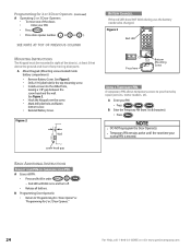
Programming for 2 or 3 Door Openers (Continued) A Operating 2 or 3 Door Openers: • To move one of any moving door parts. Figure 3 Red LED PROG DEF 123 GHI JKL MNO 456 PQRS TUV WXYZ 789 0 99V BBaatttery Press here Bottom Mounting Screw USING A TEMPORARY... 1" 8 Wall screw head gap BATTERY CHANGES. See Figure 3. • Drill a 1/16"pilot hole for 2 or 3 Door Openers." 24 For Help, call 1-800-35-GENIE or visit www.geniecompany.com BASIC ADDITIONAL INSTRUCTIONS FORGOT YOUR PIN OR CHANGING YOUR PIN. SEE NOTE AT TOP OF PREVIOUS COLUMN MOUNTING INSTRUCTIONS The...
Programming for 2 or 3 Door Openers (Continued) A Operating 2 or 3 Door Openers: • To move one of any moving door parts. Figure 3 Red LED PROG DEF 123 GHI JKL MNO 456 PQRS TUV WXYZ 789 0 99V BBaatttery Press here Bottom Mounting Screw USING A TEMPORARY... 1" 8 Wall screw head gap BATTERY CHANGES. See Figure 3. • Drill a 1/16"pilot hole for 2 or 3 Door Openers." 24 For Help, call 1-800-35-GENIE or visit www.geniecompany.com BASIC ADDITIONAL INSTRUCTIONS FORGOT YOUR PIN OR CHANGING YOUR PIN. SEE NOTE AT TOP OF PREVIOUS COLUMN MOUNTING INSTRUCTIONS The...
Owner's Manual
Page 25
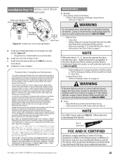
...For Help, call Customer Service at that may damage the Opener. Raise door manually 3'- 4' and verify that door stays at 1-800-35-GENIE. Slight movement is 3' - 4' above the ground, the door should stay open. Pull the Emergency Release Knob toward Power Head. See ... this device must accept any interference received, including interference that position. Release Magnetic Carriage Assembly from Drive Screw. • Lubricate Drive Screw with Part 15 of Motor Cover MAINTENANCE A Monthly: • Door springs and door hardware: - B Yearly: • Wipe off old excess lubricant ...
...For Help, call Customer Service at that may damage the Opener. Raise door manually 3'- 4' and verify that door stays at 1-800-35-GENIE. Slight movement is 3' - 4' above the ground, the door should stay open. Pull the Emergency Release Knob toward Power Head. See ... this device must accept any interference received, including interference that position. Release Magnetic Carriage Assembly from Drive Screw. • Lubricate Drive Screw with Part 15 of Motor Cover MAINTENANCE A Monthly: • Door springs and door hardware: - B Yearly: • Wipe off old excess lubricant ...
Owner's Manual
Page 30
...out of balance • Broken springs or cables • Power outages • Use of extension cords • Missing or damaged parts on parts and service. Trained Genie representatives will arrange to province. Your choice of one of incidental or consequential damages, so the above described service options is Covered Any...FOR ORDINARY USE) ARE LIMITED TO ONE YEAR FROM DATE OF PURCHASE. Some states and provinces do -it sets forth all parts. Do-It-Yourself Service: Call Genie Customer Service toll free at 1-800-354-3643, or visit our website at 1-800-654-3643. ISD995 Series - If ...
...out of balance • Broken springs or cables • Power outages • Use of extension cords • Missing or damaged parts on parts and service. Trained Genie representatives will arrange to province. Your choice of one of incidental or consequential damages, so the above described service options is Covered Any...FOR ORDINARY USE) ARE LIMITED TO ONE YEAR FROM DATE OF PURCHASE. Some states and provinces do -it sets forth all parts. Do-It-Yourself Service: Call Genie Customer Service toll free at 1-800-354-3643, or visit our website at 1-800-654-3643. ISD995 Series - If ...
