Rackmount Installation Guide
Page 5
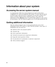
... your system Accessing the server system manual A comprehensive 7400 Server System Manual is located on the Welcome screen. To access this document (in PDF format), place the Server Companion CD into the CD drive on a system running a Window-based operating system, then follow the instructions on the Server Companion CD, which accompanied this system. Some types of information you can access are: s Hardware driver and program updates s Technical tips s Service agreement information s Technical documents and component...
... your system Accessing the server system manual A comprehensive 7400 Server System Manual is located on the Welcome screen. To access this document (in PDF format), place the Server Companion CD into the CD drive on a system running a Window-based operating system, then follow the instructions on the Server Companion CD, which accompanied this system. Some types of information you can access are: s Hardware driver and program updates s Technical tips s Service agreement information s Technical documents and component...
Rackmount Installation Guide
Page 27
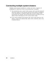
... drawers Multiple system drawers installed in a cabinet can share a single set of peripherals if a switch box, such as an autoswitcher, is relatively simple and covered in detail in the cabinet, connect the external data cables of the monitor and routes the keyboard and mouse inputs to the controlled devices. 22 Installation Turn off all system drawers and devices in the cabinet before attaching...
... drawers Multiple system drawers installed in a cabinet can share a single set of peripherals if a switch box, such as an autoswitcher, is relatively simple and covered in detail in the cabinet, connect the external data cables of the monitor and routes the keyboard and mouse inputs to the controlled devices. 22 Installation Turn off all system drawers and devices in the cabinet before attaching...
System Manual (PDF Version)
Page 4
...and drive cage fans 73 Replacing the control panel board 75 Replacing the SCSI backplane 77 Replacing the system board 80 5 Using the BIOS Setup Utility 85 About the BIOS Setup utility 85 Updating the BIOS 87 Setting the configuration switches 88 The Clear Password switch 88 The Clear CMOS switch 89 6 Managing Your System 91 Protecting against power source problems 91 Surge suppressors 91 Line conditioners 92 Uninterruptible power supplies 92 Maintaining and managing your hard drive 93 Hard drive maintenance utility 93 Hard drive management practices 94 Protecting your server...
...and drive cage fans 73 Replacing the control panel board 75 Replacing the SCSI backplane 77 Replacing the system board 80 5 Using the BIOS Setup Utility 85 About the BIOS Setup utility 85 Updating the BIOS 87 Setting the configuration switches 88 The Clear Password switch 88 The Clear CMOS switch 89 6 Managing Your System 91 Protecting against power source problems 91 Surge suppressors 91 Line conditioners 92 Uninterruptible power supplies 92 Maintaining and managing your hard drive 93 Hard drive maintenance utility 93 Hard drive management practices 94 Protecting your server...

System Manual (PDF Version)
Page 11
.... System reset button is reading or writing data. Hot-plug drive bay has room for up in appropriate RAID configuration to be set the power button to enter sleep mode rather than turning the system off . Power supply alarm speaker reset/System fault LED reset switch disables the power supply alarm speaker, if it's sounding, or resets the system fault LED, if it is replaced. Drives have room for the castors. Front panel 3 It flashes green if the power supply module fails or...
.... System reset button is reading or writing data. Hot-plug drive bay has room for up in appropriate RAID configuration to be set the power button to enter sleep mode rather than turning the system off . Power supply alarm speaker reset/System fault LED reset switch disables the power supply alarm speaker, if it's sounding, or resets the system fault LED, if it is replaced. Drives have room for the castors. Front panel 3 It flashes green if the power supply module fails or...

System Manual (PDF Version)
Page 21
... server errors. NMI (Non-Maskable Interrupt) button allows a technician to glow until the failed power supply module is removed. Chassis intrusion detection switch sends a message to enter sleep mode rather than turning the system off. System reset button lets you can set the power button to the system management hardware, logging an event when the front bezel is replaced. Front panel board 13 Power supply alarm speaker reset/System fault LED reset switch disables the power supply alarm speaker or resets the system fault LED. In an ACPI-enabled operating system like Windows...
... server errors. NMI (Non-Maskable Interrupt) button allows a technician to glow until the failed power supply module is removed. Chassis intrusion detection switch sends a message to enter sleep mode rather than turning the system off. System reset button lets you can set the power button to the system management hardware, logging an event when the front bezel is replaced. Front panel board 13 Power supply alarm speaker reset/System fault LED reset switch disables the power supply alarm speaker or resets the system fault LED. In an ACPI-enabled operating system like Windows...

System Manual (PDF Version)
Page 38
... hot-plug drives. s If you install the drive. s IDE hard drives can add drives of the following in mind: s If you install a drive, see the drive's documentation for information on configuring the drive, setting any type are attached to a controller cable, configure the drive as single if it is a hard drive or master if it in controller card, install it before you are installing a drive that support as many as two drives each. Configure the drives by using the BIOS Setup utility. The system board has...
... hot-plug drives. s If you install the drive. s IDE hard drives can add drives of the following in mind: s If you install a drive, see the drive's documentation for information on configuring the drive, setting any type are attached to a controller cable, configure the drive as single if it is a hard drive or master if it in controller card, install it before you are installing a drive that support as many as two drives each. Configure the drives by using the BIOS Setup utility. The system board has...

System Manual (PDF Version)
Page 39
... side cover panel. (See "Removing the side cover panel" on the system board and which end to connect to an add-on SCSI controller card. Each drive cable is near the bottom of the stack of drive bays. s Use the SCSI LVD cable (2 connectors) to connect the hot-plug backplane to the integrated SCSI controller on the system board or to an add-on SCSI controller card. (This cable is optional.) Replacing the diskette drive The diskette drive is clearly labeled, indicating the cable type...
... side cover panel. (See "Removing the side cover panel" on the system board and which end to connect to an add-on SCSI controller card. Each drive cable is near the bottom of the stack of drive bays. s Use the SCSI LVD cable (2 connectors) to connect the hot-plug backplane to the integrated SCSI controller on the system board or to an add-on SCSI controller card. (This cable is optional.) Replacing the diskette drive The diskette drive is clearly labeled, indicating the cable type...

System Manual (PDF Version)
Page 43
... cover panel" on page 26.) 5 Locate an available 5.25-inch drive bay. 6 Grip the mounting rails firmly with thumb and index finger and pull the filler tray carefully straight out of which came installed in the empty 5.25-inch drive bays. Installing a 3.5-inch drive in a 5.25-inch drive bay Additional 3.5-inch hard drives can also be installed in the server in your server, is required for this type...
... cover panel" on page 26.) 5 Locate an available 5.25-inch drive bay. 6 Grip the mounting rails firmly with thumb and index finger and pull the filler tray carefully straight out of which came installed in the empty 5.25-inch drive bays. Installing a 3.5-inch drive in a 5.25-inch drive bay Additional 3.5-inch hard drives can also be installed in the server in your server, is required for this type...

System Manual (PDF Version)
Page 63
... replace the processor you are installing a faster processor, your system may be installed in damage to set. When adding or replacing a processor, order a processor upgrade kit from the fan connector on the system board. (See "System board" on each processor. If you must have the same processor and FSB speed). As many as two processors may require a BIOS update to be installed on page 8 for both processors are no system board jumpers to , or failure of the fan connector.) Replacing...
... replace the processor you are installing a faster processor, your system may be installed in damage to set. When adding or replacing a processor, order a processor upgrade kit from the fan connector on the system board. (See "System board" on each processor. If you must have the same processor and FSB speed). As many as two processors may require a BIOS update to be installed on page 8 for both processors are no system board jumpers to , or failure of the fan connector.) Replacing...

System Manual (PDF Version)
Page 67
..." on page 22.) 3 Remove the bezel. (See "Removing the bezel" on page 25.) 4 Remove the left side cover panel. (See "Removing the side cover panel" on page 26.) 5 Open the locking lever on the processor socket by moving the lever slightly out to the second CPU fan connector on the system board (See "System board" on page 8 for location). 11 Replace the bezel. (See "Replacing the bezel" on...
..." on page 22.) 3 Remove the bezel. (See "Removing the bezel" on page 25.) 4 Remove the left side cover panel. (See "Removing the side cover panel" on page 26.) 5 Open the locking lever on the processor socket by moving the lever slightly out to the second CPU fan connector on the system board (See "System board" on page 8 for location). 11 Replace the bezel. (See "Replacing the bezel" on...

System Manual (PDF Version)
Page 71
Expansion cards The server has seven PCI expansion slots on the system board, that may be used for a variety of these slots support 64-bit PCI cards and five support 32-bit PCI cards. (See "System board" on page 8.) Replacing an expansion card To replace an expansion card: 1 Set any jumpers and switches on the replacement card. (See the card instructions.) 2 Turn off the system and disconnect the power cord, modem cord (if installed), and all external peripheral devices. 3 Observe all safety and static electricity precautions...
Expansion cards The server has seven PCI expansion slots on the system board, that may be used for a variety of these slots support 64-bit PCI cards and five support 32-bit PCI cards. (See "System board" on page 8.) Replacing an expansion card To replace an expansion card: 1 Set any jumpers and switches on the replacement card. (See the card instructions.) 2 Turn off the system and disconnect the power cord, modem cord (if installed), and all external peripheral devices. 3 Observe all safety and static electricity precautions...

System Manual (PDF Version)
Page 73
....) 6 Locate an available slot and remove the slot cover by pressing the expansion card retention clip back through the back panel. 7 Pull out the slot cover. 11 Connect any jumpers and switches on the card according to the card (see card documentation for additional information. You may need to reconfigure the server after replacing an expansion card. You may also need to install upgrade software that came with the card. Check the card documentation for proper cable orientation). 12 Replace...
....) 6 Locate an available slot and remove the slot cover by pressing the expansion card retention clip back through the back panel. 7 Pull out the slot cover. 11 Connect any jumpers and switches on the card according to the card (see card documentation for additional information. You may need to reconfigure the server after replacing an expansion card. You may also need to install upgrade software that came with the card. Check the card documentation for proper cable orientation). 12 Replace...

System Manual (PDF Version)
Page 78
... cover panel" on the tab to release the connector, then gently pulling the connector from the system board by both power supply status LEDs flashing and an audible alarm, or the system will fail to power up. However, if the power distribution board at the base of the power supply or some other part of the power supply fails, the entire power supply and its housing must be replaced. Replacing the power supply The redundant power supply offers fault...
... cover panel" on the tab to release the connector, then gently pulling the connector from the system board by both power supply status LEDs flashing and an audible alarm, or the system will fail to power up. However, if the power distribution board at the base of the power supply or some other part of the power supply fails, the entire power supply and its housing must be replaced. Replacing the power supply The redundant power supply offers fault...

System Manual (PDF Version)
Page 81
Replacing the back panel and drive cage fans 73 Replacing the back panel and drive cage fans The back panel fan is located behind the hot-plug drive cage, between the cage and the system board. (See the illustration on page 6 for more information.) To remove the back panel or hot-plug cage fan: 1 Turn off the system and disconnect the power cord, modem cord (if installed), and all external peripheral devices. 2 Observe...
Replacing the back panel and drive cage fans 73 Replacing the back panel and drive cage fans The back panel fan is located behind the hot-plug drive cage, between the cage and the system board. (See the illustration on page 6 for more information.) To remove the back panel or hot-plug cage fan: 1 Turn off the system and disconnect the power cord, modem cord (if installed), and all external peripheral devices. 2 Observe...

System Manual (PDF Version)
Page 88
Important All references to front, rear, left side cover panel. (See "Removing the side cover panel" on page 26.) 5 Place the chassis gently on its right side. 6 Remove all expansion cards from the system. (See "Replacing an expansion card" on page 63.) 7 Remove the back panel fan (see "Replacing the back panel and drive cage fans" on page 73.) 8 Disconnect all safety and static electricity precautions. (See "Preventing static electricity discharge...
Important All references to front, rear, left side cover panel. (See "Removing the side cover panel" on page 26.) 5 Place the chassis gently on its right side. 6 Remove all expansion cards from the system. (See "Replacing an expansion card" on page 63.) 7 Remove the back panel fan (see "Replacing the back panel and drive cage fans" on page 73.) 8 Disconnect all safety and static electricity precautions. (See "Preventing static electricity discharge...

System Manual (PDF Version)
Page 106
... management tasks, which can be set in -band monitoring, alerting, and management of the side cover as system temperature, system fans, voltage and power supply conditions, system memory, and chassis intrusion. Additional information about the ManageX Event Manager can be found under Documentation on the Server Companion CD which establish passwords and automatic system lockouts. This lock not only prevents unauthorized access to enable administration and control of the system, a key...
... management tasks, which can be set in -band monitoring, alerting, and management of the side cover as system temperature, system fans, voltage and power supply conditions, system memory, and chassis intrusion. Additional information about the ManageX Event Manager can be found under Documentation on the Server Companion CD which establish passwords and automatic system lockouts. This lock not only prevents unauthorized access to enable administration and control of the system, a key...

System Manual (PDF Version)
Page 130
... change the switch setting to AT. Keyboard not detected See "The keyboard does not work." Memory errors were detected See "The system detected memory errors while the system powered up during start up." Memory size error Enter the BIOS Setup utility, then save the memory configuration. Non-system disk or disk error Eject the diskette, then press ENTER. Check for errors. Not enough memory Close all programs that some passwords are trying to access. Keyboard clock line failure...
... change the switch setting to AT. Keyboard not detected See "The keyboard does not work." Memory errors were detected See "The system detected memory errors while the system powered up during start up." Memory size error Enter the BIOS Setup utility, then save the memory configuration. Non-system disk or disk error Eject the diskette, then press ENTER. Check for errors. Not enough memory Close all programs that some passwords are trying to access. Keyboard clock line failure...
System Manual (PDF Version)
Page 151
...drive 47 diskette drive 31 drive, RAID 45 drive, SCA 45 drive, SCSI 45 expansion cards 63 heatsink 58 hot-plug drive 38 memory 51 outriggers 16 power supply 68 power supply modules 68 processor 55 interior features 6 interrupts, system 138 J jumpers JP5 setting 10 JP6 setting 10 setting, RAID delay start 10 setting, RAID termination 10 K Kensington lock slot 5 keyboard cleaning 104 port location 5 troubleshooting 117 L LAN 100 Mbit speed LED 5 activity LED 5 port location 5 LEDs 100 Mbit speed 5 disk activity 2, 12 drive activity 11 front panel board, location 12 hot-plug drive activity 3 LAN...
...drive 47 diskette drive 31 drive, RAID 45 drive, SCA 45 drive, SCSI 45 expansion cards 63 heatsink 58 hot-plug drive 38 memory 51 outriggers 16 power supply 68 power supply modules 68 processor 55 interior features 6 interrupts, system 138 J jumpers JP5 setting 10 JP6 setting 10 setting, RAID delay start 10 setting, RAID termination 10 K Kensington lock slot 5 keyboard cleaning 104 port location 5 troubleshooting 117 L LAN 100 Mbit speed LED 5 activity LED 5 port location 5 LEDs 100 Mbit speed 5 disk activity 2, 12 drive activity 11 front panel board, location 12 hot-plug drive activity 3 LAN...

System Manual (PDF Version)
Page 152
...Index changing 99 protect switch, location 8 set user and supervisor 99 set user password only 99 using 99 peripheral devices, troubleshooting 113 ports I/O 133 keyboard 5 LAN 5 mouse 5 network 5 parallel 5 serial 5 USB 5 video 5 POST (power-on self-test) 18 power alarm speaker reset switch 3 button 17 button location 3, 13 indicator LED 2, 12 LED 17 module switches 4 supply module 68 supply specifications 133 Power menu, BIOS Setup utility 86 power source problems 91 power supply modules 4 redundant 5 replacing 70 preventing static electricity 22 printer, troubleshooting 114 processor adding...
...Index changing 99 protect switch, location 8 set user and supervisor 99 set user password only 99 using 99 peripheral devices, troubleshooting 113 ports I/O 133 keyboard 5 LAN 5 mouse 5 network 5 parallel 5 serial 5 USB 5 video 5 POST (power-on self-test) 18 power alarm speaker reset switch 3 button 17 button location 3, 13 indicator LED 2, 12 LED 17 module switches 4 supply module 68 supply specifications 133 Power menu, BIOS Setup utility 86 power source problems 91 power supply modules 4 redundant 5 replacing 70 preventing static electricity 22 printer, troubleshooting 114 processor adding...

System Manual (PDF Version)
Page 153
... button location 3, 13 resetting the system, Windows NT 20 resources DMA usage 139 I/O addresses 135 interrupts 138 memory map 138 S safety, general precautions 125 SCSI backplane features 10 device, troubleshooting 113 replacing the backplane 77 security changing passwords 99 chassis intrusion switch 99 chassis lock 2 hot-plug drive locks 3 Kensington lock slot 5 set supervisor password 99 set user password 99 setting up in BIOS 99 software locks 99 system 98 using passwords 99 Security menu, BIOS Setup utility 86 serial port location 5 Server Companion CD 101 setting delay start jumper, RAID...
... button location 3, 13 resetting the system, Windows NT 20 resources DMA usage 139 I/O addresses 135 interrupts 138 memory map 138 S safety, general precautions 125 SCSI backplane features 10 device, troubleshooting 113 replacing the backplane 77 security changing passwords 99 chassis intrusion switch 99 chassis lock 2 hot-plug drive locks 3 Kensington lock slot 5 set supervisor password 99 set user password 99 setting up in BIOS 99 software locks 99 system 98 using passwords 99 Security menu, BIOS Setup utility 86 serial port location 5 Server Companion CD 101 setting delay start jumper, RAID...