
English Manual.
Page 14
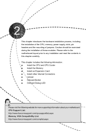
...; Install an Expansion Card ■ Install other Internal Connectors ■ Jumper ■ Onboard Button ■ Onboard Debug LED Please visit the following website for more supporting information about your motherboard. CPU Support List: http://www.foxconnsupport.com/cpusupportlist.aspx Memory, VGA Compatibility List: http://www.foxconnsupport.com/complist.aspx This chapter introduces the hardware installation process, including the installation of the CPU, memory, power supply, slots, pin headers and the mounting of these modules. Please refer to the motherboard layout...
...; Install an Expansion Card ■ Install other Internal Connectors ■ Jumper ■ Onboard Button ■ Onboard Debug LED Please visit the following website for more supporting information about your motherboard. CPU Support List: http://www.foxconnsupport.com/cpusupportlist.aspx Memory, VGA Compatibility List: http://www.foxconnsupport.com/complist.aspx This chapter introduces the hardware installation process, including the installation of the CPU, memory, power supply, slots, pin headers and the mounting of these modules. Please refer to the motherboard layout...
English Manual.
Page 20
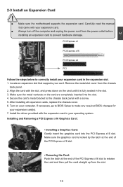
... manual that supports your expansion card. ■ Always turn off the computer and unplug the power cord from the chassis back panel. 2. Align the card with your card. Turn on the card are completely inserted into the PCI Express x16 slot. Secure the card's metal bracket to the chassis back panel with the expansion card in your computer. Installing and Removing a PCI Express x16 Graphics Card : • Installing a Graphics Card: Gently insert the graphics card into the slot. 4. Remove the metal slot...
... manual that supports your expansion card. ■ Always turn off the computer and unplug the power cord from the chassis back panel. 2. Align the card with your card. Turn on the card are completely inserted into the PCI Express x16 slot. Secure the card's metal bracket to the chassis back panel with the expansion card in your computer. Installing and Removing a PCI Express x16 Graphics Card : • Installing a Graphics Card: Gently insert the graphics card into the slot. 4. Remove the metal slot...

English Manual.
Page 23
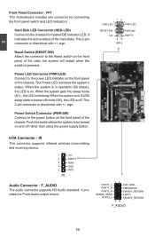
... turned on the front panel of the chassis. Hard Disk LED Connector (HDD-LED) Connect to the power LED indicator on the front panel of the hard disks. It indicates the active status of the chassis. Reset Switch (RESET-SW) Attach the connector to the power button on the front panel of the case; When the system is in S3/S4 sleep state or power off . Power Switch Connector (PWR-SW) Connect to the Reset switch on and off rather than using the power supply button...
... turned on the front panel of the chassis. Hard Disk LED Connector (HDD-LED) Connect to the power LED indicator on the front panel of the hard disks. It indicates the active status of the chassis. Reset Switch (RESET-SW) Attach the connector to the power button on the front panel of the case; When the system is in S3/S4 sleep state or power off . Power Switch Connector (PWR-SW) Connect to the Reset switch on and off rather than using the power supply button...

English Manual.
Page 25
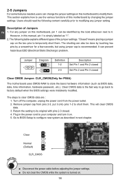
...! 1 Clear 2 3 Normal 1 (Default) 2 3 CLR_CMOS ■ Disconnect the power cable before adjusting the jumper settings. ■ Do not clear the CMOS while the system is simply labeled as BIOS data, date, time information, hardware password...etc.). Go to BIOS Setup to modifying any jumper on this motherboard, pin 1 can be done by touching two pins by the bold silkscreen next to factory default when the BIOS settings were mistakenly modified. Users...
...! 1 Clear 2 3 Normal 1 (Default) 2 3 CLR_CMOS ■ Disconnect the power cable before adjusting the jumper settings. ■ Do not clear the CMOS while the system is simply labeled as BIOS data, date, time information, hardware password...etc.). Go to BIOS Setup to modifying any jumper on this motherboard, pin 1 can be done by touching two pins by the bold silkscreen next to factory default when the BIOS settings were mistakenly modified. Users...

English Manual.
Page 26
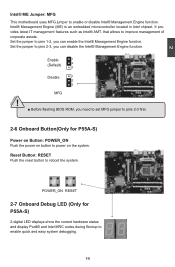
.... Reset Button: RESET Push the reset button to enable or disable Intel® Management Engine function. Set the jumper to power on the system. Set the jumper to pins 2-3, you need to set MFG jumper to pins 2-3 first. 2-6 Onboard Button(Only for P55A-S) 2-digital LED displays show the current hardware status and display Port80 and Intel MRC codes during Bootup to improve management of corporate assets. 2 Intel® ME Jumper: MFG This motherboard uses MFG jumper to...
.... Reset Button: RESET Push the reset button to enable or disable Intel® Management Engine function. Set the jumper to power on the system. Set the jumper to pins 2-3, you need to set MFG jumper to pins 2-3 first. 2-6 Onboard Button(Only for P55A-S) 2-digital LED displays show the current hardware status and display Port80 and Intel MRC codes during Bootup to improve management of corporate assets. 2 Intel® ME Jumper: MFG This motherboard uses MFG jumper to...
English Manual.
Page 30
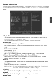
... settings. ► Keyboard The system boot will not stop if an error is detected during powering up /down keys to select an item, then use the or keys to ► Third IDE Master [Not Detected] configure system Time. ► Fourth IDE Master [Not Detected] Halt On Keyboard Mouse [All Errors, But ...] [Disabled] [Disabled] Model Name : P55A/P55A-S BIOS Version : 945F1P01 Memory : 512MB MAC Address : 00-22-68-2E-26-1D Intel (R) Core...
... settings. ► Keyboard The system boot will not stop if an error is detected during powering up /down keys to select an item, then use the or keys to ► Third IDE Master [Not Detected] configure system Time. ► Fourth IDE Master [Not Detected] Halt On Keyboard Mouse [All Errors, But ...] [Disabled] [Disabled] Model Name : P55A/P55A-S BIOS Version : 945F1P01 Memory : 512MB MAC Address : 00-22-68-2E-26-1D Intel (R) Core...
English Manual.
Page 32
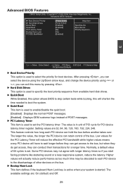
..., a default value of 64 cycles is set the PCI latency timer. Some PCI devices may be allocated to each PCI device can hold the bus before they can select the device using the Up/Down arrow keys, and change the device priority using or ; Advanced BIOS Features ► Boot Device Priority ► Hard Disk Drives Quick Boot Quiet Boot PCI Latency Timer Bootup Num-Lock PCI IDE BusMaster [[PPrreessssEEnntteerr]] Help Item [Press Enter] [Enabled] Specifies the [Enabled] Boot Device [64...
..., a default value of 64 cycles is set the PCI latency timer. Some PCI devices may be allocated to each PCI device can hold the bus before they can select the device using the Up/Down arrow keys, and change the device priority using or ; Advanced BIOS Features ► Boot Device Priority ► Hard Disk Drives Quick Boot Quiet Boot PCI Latency Timer Bootup Num-Lock PCI IDE BusMaster [[PPrreessssEEnntteerr]] Help Item [Press Enter] [Enabled] Specifies the [Enabled] Boot Device [64...
English Manual.
Page 35
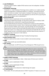
... The selected option will be entered into C State Package limit register. ► C1 Auto Demotion When enable, CPU will be met, including CPU, chipset, motherboard, BIOS and operation system. Execute Disable Bit allows the processor to insert code in memory by where application code can enable/disable the EIST (Processor Power Management, PPM) through this feature and the setting is used to enable/disable it cannot. By combining Execute Disable Bit with Execute Disable Bit-enabled systems can...
... The selected option will be entered into C State Package limit register. ► C1 Auto Demotion When enable, CPU will be met, including CPU, chipset, motherboard, BIOS and operation system. Execute Disable Bit allows the processor to insert code in memory by where application code can enable/disable the EIST (Processor Power Management, PPM) through this feature and the setting is used to enable/disable it cannot. By combining Execute Disable Bit with Execute Disable Bit-enabled systems can...
English Manual.
Page 39
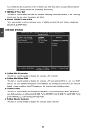
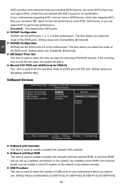
... Help F9:Optimized Defaults ► OnBoard LAN Controller This item is used to enable or disable the onboard LAN controller. ► OnBoard LAN Boot ROM This item is used to use. By installing a boot ROM in the network board, you can enable a client PC system on the network to be booted remotely. ► USB Functions This item is used to enable or disable the onboard LAN boot optional ROM. 3 SATA#2 are the SATA ports 5,6 of the SATA ports. OnBoard Devices CMOS Setup Utility - A LAN boot ROM lets you set the operation mode of USB ports on the network. This item...
... Help F9:Optimized Defaults ► OnBoard LAN Controller This item is used to enable or disable the onboard LAN controller. ► OnBoard LAN Boot ROM This item is used to use. By installing a boot ROM in the network board, you can enable a client PC system on the network to be booted remotely. ► USB Functions This item is used to enable or disable the onboard LAN boot optional ROM. 3 SATA#2 are the SATA ports 5,6 of the SATA ports. OnBoard Devices CMOS Setup Utility - A LAN boot ROM lets you set the operation mode of USB ports on the network. This item...
English Manual.
Page 48
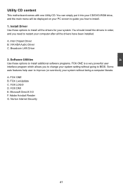
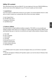
... LAN Driver 2. Some auto features help user to improve (or overclock) your PC screen to guide you how to BIOS. A. A. FOX LiveUpdate C. Microsoft DirectX 9.0 F. Adobe Acrobat Reader G. Intel Chipset Driver B. FOX ONE B. FOX DMI E. You can simply put it into your CD/DVD-ROM drive, and the main menu will be displayed on your system without going to install. 1. Install Driver Use these options to install additional software programs. FOX ONE is a very powerful user...
... LAN Driver 2. Some auto features help user to improve (or overclock) your PC screen to guide you how to BIOS. A. A. FOX LiveUpdate C. Microsoft DirectX 9.0 F. Adobe Acrobat Reader G. Intel Chipset Driver B. FOX ONE B. FOX DMI E. You can simply put it into your CD/DVD-ROM drive, and the main menu will be displayed on your system without going to install. 1. Install Driver Use these options to install additional software programs. FOX ONE is a very powerful user...
English Manual.
Page 14
... be exercised during the installation of jumpers. This chapter includes the following information : ■ Install the CPU and CPU Cooler ■ Install the Memory ■ Install an Expansion Card ■ Install other Internal Connectors ■ Jumper ■ Onboard Button ■ Onboard Debug LED Please visit the following website for more supporting information about your motherboard. This chapter introduces the hardware installation process, including the installation of the CPU, memory, power supply, slots, pin headers and the mounting of...
... be exercised during the installation of jumpers. This chapter includes the following information : ■ Install the CPU and CPU Cooler ■ Install the Memory ■ Install an Expansion Card ■ Install other Internal Connectors ■ Jumper ■ Onboard Button ■ Onboard Debug LED Please visit the following website for more supporting information about your motherboard. This chapter introduces the hardware installation process, including the installation of the CPU, memory, power supply, slots, pin headers and the mounting of...
English Manual.
Page 23
... receiving device. 1 2 3 4 5 IR +5V EMPTY IRRX GND IRTX Audio Connector : F_AUDIO The audio connector supports HD Audio standard. Power Switch Connector (PWR-SW) Connect to the chassis front panel IDE indicator LED. sign. The Power LED indicates the system's status. Reset Switch (RESET-SW) Attach the connector to be turned on . Push this switch allows the system to the Reset switch on the front panel of the hard disks. PWR-LED - This 2-pin connector is on and off . 2 Front Panel Connector : FP1 This motherboard...
... receiving device. 1 2 3 4 5 IR +5V EMPTY IRRX GND IRTX Audio Connector : F_AUDIO The audio connector supports HD Audio standard. Power Switch Connector (PWR-SW) Connect to the chassis front panel IDE indicator LED. sign. The Power LED indicates the system's status. Reset Switch (RESET-SW) Attach the connector to be turned on . Push this switch allows the system to the Reset switch on the front panel of the hard disks. PWR-LED - This 2-pin connector is on and off . 2 Front Panel Connector : FP1 This motherboard...
English Manual.
Page 25
... pins 1-2 to short them. It can prevent hazardous ESD (Electrical Static Discharge) problem. Remove jumper cap from the power outlet. 2. Go to BIOS Setup to store the basic hardware information (such as BIOS data, date, time information, hardware password...etc.). This will clear CMOS data. 3. This section explains how to use the various functions of this motherboard to your computer and turn it . Jumper 1 Diagram 1 1 Definition 1-2 2-3 Description Set Pin...
... pins 1-2 to short them. It can prevent hazardous ESD (Electrical Static Discharge) problem. Remove jumper cap from the power outlet. 2. Go to BIOS Setup to store the basic hardware information (such as BIOS data, date, time information, hardware password...etc.). This will clear CMOS data. 3. This section explains how to use the various functions of this motherboard to your computer and turn it . Jumper 1 Diagram 1 1 Definition 1-2 2-3 Description Set Pin...
English Manual.
Page 26
Enable 1 (Default) 2 3 Disable 1 2 3 MFG ! ■ Before flashing BIOS ROM, you need to set MFG jumper to pins 2-3 first. 2-6 Onboard Button(Only for P55A-S) 2-digital LED displays show the current hardware status and display Port80 and Intel MRC codes during Bootup to improve management of corporate assets. Reset Button: RESET Push the reset button to power on the system. Set the jumper to pins 1-2, you can disable the Intel® Management Engine function. Intel® Management Engine (ME...
Enable 1 (Default) 2 3 Disable 1 2 3 MFG ! ■ Before flashing BIOS ROM, you need to set MFG jumper to pins 2-3 first. 2-6 Onboard Button(Only for P55A-S) 2-digital LED displays show the current hardware status and display Port80 and Intel MRC codes during Bootup to improve management of corporate assets. Reset Button: RESET Push the reset button to power on the system. Set the jumper to pins 1-2, you can disable the Intel® Management Engine function. Intel® Management Engine (ME...

English Manual.
Page 32
.... Advanced BIOS Features ► Boot Device Priority ► Hard Disk Drives Quick Boot Quiet Boot PCI Latency Timer Bootup Num-Lock PCI IDE BusMaster [[PPrreessssEEnntteerr]] Help Item [Press Enter] [Enabled] Specifies the [Enabled] Boot Device [64] Priority sequence . [On] [Enabled] 3 Move Enter:Select +/-/:Value F10:Save ESC:Exit F1:General Help F9:Optimized Defaults ► Boot Device Priority This option is used to the disadvantage of PCI cycle for boot devices. This feature controls how long each PCI device to...
.... Advanced BIOS Features ► Boot Device Priority ► Hard Disk Drives Quick Boot Quiet Boot PCI Latency Timer Bootup Num-Lock PCI IDE BusMaster [[PPrreessssEEnntteerr]] Help Item [Press Enter] [Enabled] Specifies the [Enabled] Boot Device [64] Priority sequence . [On] [Enabled] 3 Move Enter:Select +/-/:Value F10:Save ESC:Exit F1:General Help F9:Optimized Defaults ► Boot Device Priority This option is used to the disadvantage of PCI cycle for boot devices. This feature controls how long each PCI device to...

English Manual.
Page 35
...; Active Processor Cores This item is used to enable/disable it cannot. Execute Disable Bit allows the processor to classify areas in each processor package. ► A20M Legacy OSes and APs may need for WinXP. ► Virtualization Technology Virtualization (i.e. Set [Disabled] for virus-related repairs. There are some system requirements must be displayed only when the CPU is supporting this item. ! Intel® Vanderpool Technology) allows a platform to insert code in...
...; Active Processor Cores This item is used to enable/disable it cannot. Execute Disable Bit allows the processor to classify areas in each processor package. ► A20M Legacy OSes and APs may need for WinXP. ► Virtualization Technology Virtualization (i.e. Set [Disabled] for virus-related repairs. There are some system requirements must be displayed only when the CPU is supporting this item. ! Intel® Vanderpool Technology) allows a platform to insert code in...
English Manual.
Page 39
...IDE]. OnBoard Devices CMOS Setup Utility - If your motherboard which also supports AHCI, then you can select IDE option to have a SATA device, which you can enable a client PC system on the network to be booted remotely. ► USB Functions This item is used to enable or disable the onboard LAN boot optional ROM. This item allows you select the mode of the SATA ports. OnBoard Devices OnBoard LAN Controller [Enabled] Help Item OnBoard LAN Boot ROM [Disabled] USB Functions [14 USB Ports] Options OnBoard Audio Controller [Enabled] Disabled...
...IDE]. OnBoard Devices CMOS Setup Utility - If your motherboard which also supports AHCI, then you can select IDE option to have a SATA device, which you can enable a client PC system on the network to be booted remotely. ► USB Functions This item is used to enable or disable the onboard LAN boot optional ROM. This item allows you select the mode of the SATA ports. OnBoard Devices OnBoard LAN Controller [Enabled] Help Item OnBoard LAN Boot ROM [Disabled] USB Functions [14 USB Ports] Options OnBoard Audio Controller [Enabled] Disabled...
English Manual.
Page 48
... install. 1. A. Norton Internet Security H. Broadcom LAN Driver D. FOX LOGO D. A. FOX DMI E. Intel Chipset Driver B. Adobe Acrobat Reader G. FOX LiveUpdate C. Software Utilities Use these options to BIOS. You should install the drivers in order, and you need to restart your PC screen to guide you run CD drive in operation system. *2 : The item will appear in Windows XP operation system, but it into your CD/DVD-ROM drive, and the main menu...
... install. 1. A. Norton Internet Security H. Broadcom LAN Driver D. FOX LOGO D. A. FOX DMI E. Intel Chipset Driver B. Adobe Acrobat Reader G. FOX LiveUpdate C. Software Utilities Use these options to BIOS. You should install the drivers in order, and you need to restart your PC screen to guide you run CD drive in operation system. *2 : The item will appear in Windows XP operation system, but it into your CD/DVD-ROM drive, and the main menu...

English Manual.
Page 106
... 74.5GB 149.0GB 74.5GB Type/Status(Vol ID) Recovery Disk(0) Offline Disk(0) Member Disk(0) Non-RAID Disk 5 Exit RAID BIOS [↑↓]-Select [ESC]-Exit [ENTER]-Select Menu 1. Restart computer to Non-RAID 6. Reset Disks to exit Intel® Matrix Storage Manager program. Remove any diskette from floppy drive. 5. Create RAID Volume 4. If you do not remove irrelevant hard disk, Windows may detect it during the installation, and you want to exit...
... 74.5GB 149.0GB 74.5GB Type/Status(Vol ID) Recovery Disk(0) Offline Disk(0) Member Disk(0) Non-RAID Disk 5 Exit RAID BIOS [↑↓]-Select [ESC]-Exit [ENTER]-Select Menu 1. Restart computer to Non-RAID 6. Reset Disks to exit Intel® Matrix Storage Manager program. Remove any diskette from floppy drive. 5. Create RAID Volume 4. If you do not remove irrelevant hard disk, Windows may detect it during the installation, and you want to exit...
English Manual.
Page 108
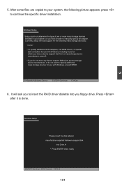
... 6. Currently, Setup will ask you floppy drive. Windows Setup Setup could not determine the type of one or more mass storage devices installed in your system, the following mass storage device(s): * To specify additional SCSI adapters, CD-ROM drivers, or special disk controllers for use with Windows, press ENTER. Press after it is done. 5 Windows Setup Please insert the disk labeled manufacturer-supplied hardware support disk into you to continue the specific driver installation. After some files are copied...
... 6. Currently, Setup will ask you floppy drive. Windows Setup Setup could not determine the type of one or more mass storage devices installed in your system, the following mass storage device(s): * To specify additional SCSI adapters, CD-ROM drivers, or special disk controllers for use with Windows, press ENTER. Press after it is done. 5 Windows Setup Please insert the disk labeled manufacturer-supplied hardware support disk into you to continue the specific driver installation. After some files are copied...


