User manual
Page 20
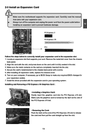
... the motherboard supports the expansion card. Carefully read the manual that supports your operating system. Turn on your expansion card. ■ Always turn off the computer and unplug the power cord from the power outlet before installing an expansion card to prevent hardware damage. If necessary, go to BIOS Setup to the chassis back panel with your computer. Installing and Removing a PCI Express x16 Graphics Card : • Installing a Graphics Card: Gently insert the graphics card into the slot...
... the motherboard supports the expansion card. Carefully read the manual that supports your operating system. Turn on your expansion card. ■ Always turn off the computer and unplug the power cord from the power outlet before installing an expansion card to prevent hardware damage. If necessary, go to BIOS Setup to the chassis back panel with your computer. Installing and Removing a PCI Express x16 Graphics Card : • Installing a Graphics Card: Gently insert the graphics card into the slot...
User manual
Page 23
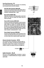
... a Sony standard audio connector, it can be turned on the chassis. sign. Push this connector. RESET-SW PWR-SW NC EMPTY 9 10 FP1 Chassis Intruder Connector : INTR2 The connector can be connected to a security switch on and off rather than using the power supply button. 12 + + HDD-LED - This 2-pin connector is blinking; The Power LED indicates the system's status. PWR-LED - Hard Disk LED Connector (HDD-LED) Connect to the power LED indicator on the front panel of the chassis. Reset Switch (RESET-SW) Attach...
... a Sony standard audio connector, it can be turned on the chassis. sign. Push this connector. RESET-SW PWR-SW NC EMPTY 9 10 FP1 Chassis Intruder Connector : INTR2 The connector can be connected to a security switch on and off rather than using the power supply button. 12 + + HDD-LED - This 2-pin connector is blinking; The Power LED indicates the system's status. PWR-LED - Hard Disk LED Connector (HDD-LED) Connect to the power LED indicator on the front panel of the chassis. Reset Switch (RESET-SW) Attach...
User manual
Page 25
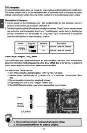
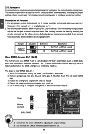
.... Jumper 1 Diagram 1 1 Definition 1-2 2-3 Description Set Pin 1 and Pin 2 closed Set Pin 2 and Pin 3 closed . 4. Remove jumper cap from the power outlet. 2. Go to BIOS Setup to factory default when the BIOS settings were mistakenly modified. This section explains how to use the various functions of this motherboard by a screwdriver for a few seconds, but using jumper cap is the fast way to go back to configure new system as described in this manual, pin...
.... Jumper 1 Diagram 1 1 Definition 1-2 2-3 Description Set Pin 1 and Pin 2 closed Set Pin 2 and Pin 3 closed . 4. Remove jumper cap from the power outlet. 2. Go to BIOS Setup to factory default when the BIOS settings were mistakenly modified. This section explains how to use the various functions of this motherboard by a screwdriver for a few seconds, but using jumper cap is the fast way to go back to configure new system as described in this manual, pin...
User manual
Page 26
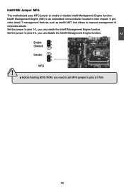
... motherboard uses MFG jumper to improve management of corporate assets. Set the jumper to pins 2-3, you need to set MFG jumper to pins 1-2, you can disable the Intel® Management Engine function. It provides latest IT management features such as Intel® AMT, that allows to enable or disable Intel® Management Engine function. CAUTION 19 19 Enable 1 (Default) 2 3 Disable 1 2 3 MFG ! ■ Before flashing BIOS ROM, you can enable...
... motherboard uses MFG jumper to improve management of corporate assets. Set the jumper to pins 2-3, you need to set MFG jumper to pins 1-2, you can disable the Intel® Management Engine function. It provides latest IT management features such as Intel® AMT, that allows to enable or disable Intel® Management Engine function. CAUTION 19 19 Enable 1 (Default) 2 3 Disable 1 2 3 MFG ! ■ Before flashing BIOS ROM, you can enable...
User manual
Page 28
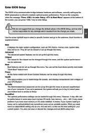
... correct password before boot or access to maintain optimal system performance. Power on the computer, when the message "Press to enter Setup, to Boot Menu" appears at the bottom of the screen, you to key in some ways (such as CPU Name, memory size, system date, time and so on. Each function is explained below: Main It displays the basic system configuration, such as less I/O cards, less memory...
... correct password before boot or access to maintain optimal system performance. Power on the computer, when the message "Press to enter Setup, to Boot Menu" appears at the bottom of the screen, you to key in some ways (such as CPU Name, memory size, system date, time and so on. Each function is explained below: Main It displays the basic system configuration, such as less I/O cards, less memory...
User manual
Page 32
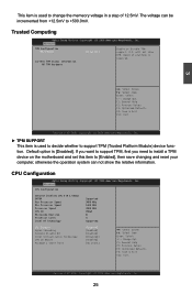
... Aptio Setup Utility - F1: General Help F2: Previous Values F3: Optimized Defaults F4: Save & Exit ESC: Exit Version 2.02.1205. Advanced TPM Configuration TPM SUPPORT Current TPM Status Information NO TPM Hardware [Disabled] Enable or Disable TPM support. Advanced CPU Configuration Genuine Intel(R) CPU 0 @ 3.00GHz EMT64 Supported Max Processor Speed 3000 MHz Min Processor Speed 1600 MHz Processor Speed 3000 MHz CPU ID 206a3 Microcode Revision 8 Processor Cores 4 Intel HT Technology Supported C1E Support Hyper-threading Execute Disable Bit...
... Aptio Setup Utility - F1: General Help F2: Previous Values F3: Optimized Defaults F4: Save & Exit ESC: Exit Version 2.02.1205. Advanced TPM Configuration TPM SUPPORT Current TPM Status Information NO TPM Hardware [Disabled] Enable or Disable TPM support. Advanced CPU Configuration Genuine Intel(R) CPU 0 @ 3.00GHz EMT64 Supported Max Processor Speed 3000 MHz Min Processor Speed 1600 MHz Processor Speed 3000 MHz CPU ID 206a3 Microcode Revision 8 Processor Cores 4 Intel HT Technology Supported C1E Support Hyper-threading Execute Disable Bit...
User manual
Page 33
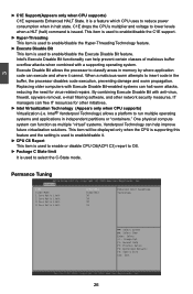
... enable/disable the Execute Disable Bit feature. When a malicious worm attempts to run multiple operating systems and applications in the buffer, the processor disables code execution, preventing damage and worm propagation. Permance Tuning Aptio Setup Utility - Intel® Vanderpool Technology) allows a platform to insert code in independent partitions or "containers." Replacing older computers with anti-virus, firewall, spyware removal, e-mail filtering software, and other network...
... enable/disable the Execute Disable Bit feature. When a malicious worm attempts to run multiple operating systems and applications in the buffer, the processor disables code execution, preventing damage and worm propagation. Permance Tuning Aptio Setup Utility - Intel® Vanderpool Technology) allows a platform to insert code in independent partitions or "containers." Replacing older computers with anti-virus, firewall, spyware removal, e-mail filtering software, and other network...
User manual
Page 34
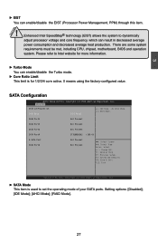
... F2: Previous Values F3: Optimized Defaults F4: Save & Exit ESC: Exit Version 2.02.1205. Please refer to Intel website for 1/2/3/4 core active. 0 means using the factory-configured value. Setting options: [Disabled]; [IDE Mode]; [AHCI Mode]; [RAID Mode]. 27 Enhanced Intel SpeedStep® technology (EIST) allows the system to set the operating mode of your SATA ports. There are some system requirements must be met, including CPU, chipset, motherboard, BIOS and operation system. C opyright...
... F2: Previous Values F3: Optimized Defaults F4: Save & Exit ESC: Exit Version 2.02.1205. Please refer to Intel website for 1/2/3/4 core active. 0 means using the factory-configured value. Setting options: [Disabled]; [IDE Mode]; [AHCI Mode]; [RAID Mode]. 27 Enhanced Intel SpeedStep® technology (EIST) allows the system to set the operating mode of your SATA ports. There are some system requirements must be met, including CPU, chipset, motherboard, BIOS and operation system. C opyright...
User manual
Page 36
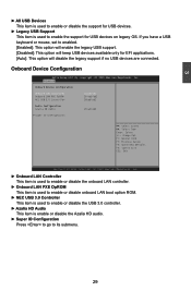
... LAN PXE OpROM This item is used to enable or disable onboard LAN boot option ROM. ► NEC USB 3.0 Controller This item is enable or disable the Azalia HD audio. ► Super IO Configuration Press to go to its submenu. 29 Onboard Device Configuration Aptio Setup Utility - Advanced Onboard Device Configuration Onboard LAN Controller Onboard LAN PXE OpROM NEC USB 3.0 Controller [Enabled] [Disabled] [Enabled] Audio Configuration Azalia HD Audio [Enabled] ▶ Super IO Configuration → ← : Select Screen ↑ ↓ : Select Item Enter: Select +/-: Change...
... LAN PXE OpROM This item is used to enable or disable onboard LAN boot option ROM. ► NEC USB 3.0 Controller This item is enable or disable the Azalia HD audio. ► Super IO Configuration Press to go to its submenu. 29 Onboard Device Configuration Aptio Setup Utility - Advanced Onboard Device Configuration Onboard LAN Controller Onboard LAN PXE OpROM NEC USB 3.0 Controller [Enabled] [Disabled] [Enabled] Audio Configuration Azalia HD Audio [Enabled] ▶ Super IO Configuration → ← : Select Screen ↑ ↓ : Select Item Enter: Select +/-: Change...
User manual
Page 47
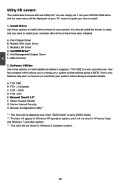
... auto features help user to BIOS. FOX LOGO D. FOX DMI E. Software Utilities Use these options to [RAID Mode]. *2 : The item will appear in Windows Vista and Windows 7 operation system. *3 : This item will be displayed on your PC screen to guide you need to install. 1. FOX LiveUpdate C. You can simply put it will not show in Windows XP operation system, but it into your CD/DVD-ROM drive, and the main menu...
... auto features help user to BIOS. FOX LOGO D. FOX DMI E. Software Utilities Use these options to [RAID Mode]. *2 : The item will appear in Windows Vista and Windows 7 operation system. *3 : This item will be displayed on your PC screen to guide you need to install. 1. FOX LiveUpdate C. You can simply put it will not show in Windows XP operation system, but it into your CD/DVD-ROM drive, and the main menu...
User manual
Page 76
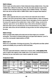
... need four SATA hard disks. RAID 1 (Mirror) RAID 1 writes duplicate data onto a pair of drives and reads both sets of data in excellent performance and good fault tolerance. Under a RAID 1 setup, an extra drive called the "spare drive" can be affected as long as there are other working drives in the array. Comparison Table : Solution RAID0 RAID1 RAID5 Hard Disks No. >=2 2 >=3 RAID10 >=4 (Even number) Recovery 2 Capacity All...
... need four SATA hard disks. RAID 1 (Mirror) RAID 1 writes duplicate data onto a pair of drives and reads both sets of data in excellent performance and good fault tolerance. Under a RAID 1 setup, an extra drive called the "spare drive" can be affected as long as there are other working drives in the array. Comparison Table : Solution RAID0 RAID1 RAID5 Hard Disks No. >=2 2 >=3 RAID10 >=4 (Even number) Recovery 2 Capacity All...
User manual
Page 108
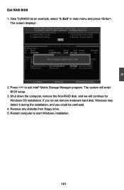
... CCoorrppoorraattiioonn.AlAl lRl RigihgthstsRReseesrevrevde.d. [ MAIN MENU ] 1. The system will continue for Windows OS installation. Take TryRAID5 as an example, select "5. Create RAID Volume 3. Recover Volume Options 5. Delete RAID Volume 4. Shut down the computer, remove the Non-RAID disk, and we will enter BIOS setup. 3. Remove any diskette from floppy drive. 5. Exit RAID BIOS 1. Reset Disks to exit? Exit [ DISK/VOLUME INFORMATION ] RAID Volume : ID Name Level Stripe Size Status Bootable �0��...
... CCoorrppoorraattiioonn.AlAl lRl RigihgthstsRReseesrevrevde.d. [ MAIN MENU ] 1. The system will continue for Windows OS installation. Take TryRAID5 as an example, select "5. Create RAID Volume 3. Recover Volume Options 5. Delete RAID Volume 4. Shut down the computer, remove the Non-RAID disk, and we will enter BIOS setup. 3. Remove any diskette from floppy drive. 5. Exit RAID BIOS 1. Reset Disks to exit? Exit [ DISK/VOLUME INFORMATION ] RAID Volume : ID Name Level Stripe Size Status Bootable �0��...
User manual
Page 110
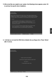
... storage devices for use with Windows, including those for use with Windows, press ENTER. S=Specify Additional Device ENTER=Continue F3=Exit 6. After some files are copied to your system, or you floppy drive. Windows Setup Setup could not determine the type of one or more mass storage devices installed in your system, the following mass storage device(s): * To specify additional SCSI adapters, CD-ROM drivers, or special disk controllers for which you have a device support disk from a mass storage device...
... storage devices for use with Windows, including those for use with Windows, press ENTER. S=Specify Additional Device ENTER=Continue F3=Exit 6. After some files are copied to your system, or you floppy drive. Windows Setup Setup could not determine the type of one or more mass storage devices installed in your system, the following mass storage device(s): * To specify additional SCSI adapters, CD-ROM drivers, or special disk controllers for which you have a device support disk from a mass storage device...

User manual
Page 23
... 2-pin connector is on the front panel of the case; The system can be connected to the power button on . Hard Disk LED Connector (HDD-LED) Connect to the Reset switch on the chassis. RESET-SW PWR-SW NC EMPTY 9 10 FP1 Chassis Intruder Connector : INTR2 The connector can detect the chassis intrusion through a CD/DVD audio cable. PWR-LED - Reset Switch (RESET-SW) Attach the connector to the chassis front panel IDE indicator LED. 2 Front Panel Connector : FP1 This motherboard includes one connector for connecting the front panel switch and LED...
... 2-pin connector is on the front panel of the case; The system can be connected to the power button on . Hard Disk LED Connector (HDD-LED) Connect to the Reset switch on the chassis. RESET-SW PWR-SW NC EMPTY 9 10 FP1 Chassis Intruder Connector : INTR2 The connector can detect the chassis intrusion through a CD/DVD audio cable. PWR-LED - Reset Switch (RESET-SW) Attach the connector to the chassis front panel IDE indicator LED. 2 Front Panel Connector : FP1 This motherboard includes one connector for connecting the front panel switch and LED...
User manual
Page 25
... system as "1". 2. For any jumper setting. "Closed" means placing a jumper cap on . 18 18 Remove jumper cap from the power outlet. 2. Return the setting to its original with pins 2-3 closed Clear CMOS Jumper: CLR_CMOS The motherboard uses CMOS RAM to short them . Jumper 1 Diagram 1 1 Definition 1-2 2-3 Description Set Pin 1 and Pin 2 closed Set Pin 2 and Pin 3 closed . 4. Go to BIOS Setup to factory default when the BIOS settings were mistakenly modified. 2 2-5 Jumpers For some features needed, users can also be identified by...
... system as "1". 2. For any jumper setting. "Closed" means placing a jumper cap on . 18 18 Remove jumper cap from the power outlet. 2. Return the setting to its original with pins 2-3 closed Clear CMOS Jumper: CLR_CMOS The motherboard uses CMOS RAM to short them . Jumper 1 Diagram 1 1 Definition 1-2 2-3 Description Set Pin 1 and Pin 2 closed Set Pin 2 and Pin 3 closed . 4. Go to BIOS Setup to factory default when the BIOS settings were mistakenly modified. 2 2-5 Jumpers For some features needed, users can also be identified by...

User manual
Page 32
... Supported Max Processor Speed 3000 MHz Min Processor Speed 1600 MHz Processor Speed 3000 MHz CPU ID 206a3 Microcode Revision 8 Processor Cores 4 Intel HT Technology Supported C1E Support Hyper-threading Execute Disable Bit Intel Virtualization Technology CPU C6 Report Package C State limit [Enabled] [Enabled] [Enabled] [Disabled] [Enabled] [No Limit] → ← : Select Screen ↑ ↓ : Select Item Enter: Select +/-: Change Opt. F1: General Help F2: Previous Values F3: Optimized Defaults F4: Save & Exit ESC: Exit Version 2.02.1205. Default option is used...
... Supported Max Processor Speed 3000 MHz Min Processor Speed 1600 MHz Processor Speed 3000 MHz CPU ID 206a3 Microcode Revision 8 Processor Cores 4 Intel HT Technology Supported C1E Support Hyper-threading Execute Disable Bit Intel Virtualization Technology CPU C6 Report Package C State limit [Enabled] [Enabled] [Enabled] [Disabled] [Enabled] [No Limit] → ← : Select Screen ↑ ↓ : Select Item Enter: Select +/-: Change Opt. F1: General Help F2: Previous Values F3: Optimized Defaults F4: Save & Exit ESC: Exit Version 2.02.1205. Default option is used...

User manual
Page 33
... Technology can help improve future virtualization solutions. This item will be displayed only when the CPU is supporting this feature and the setting is used to enable/disable it cannot. Advanced EIST Turbo Mode 1 Core Ratio Limit 2 Core Ratio Limit 3 Core Ratio Limit 4 Core Ratio Limit [Enabled] [Enabled] 36 34 32 31 Enhanced Intel SpeedStep Technology → ← : Select Screen ↑ ↓ : Select Item Enter: Select +/-: Change Opt. Intel's Execute Disable Bit...
... Technology can help improve future virtualization solutions. This item will be displayed only when the CPU is supporting this feature and the setting is used to enable/disable it cannot. Advanced EIST Turbo Mode 1 Core Ratio Limit 2 Core Ratio Limit 3 Core Ratio Limit 4 Core Ratio Limit [Enabled] [Enabled] 36 34 32 31 Enhanced Intel SpeedStep Technology → ← : Select Screen ↑ ↓ : Select Item Enter: Select +/-: Change Opt. Intel's Execute Disable Bit...

User manual
Page 36
...are connected. Onboard Device Configuration Aptio Setup Utility - F1: General Help F2: Previous Values F3: Optimized Defaults F4: Save & Exit ESC: Exit Version 2.02.1205. If you have a USB keyboard or mouse, set to its submenu. 29 C opyright (C) 2010 American Megatrends, Inc. Advanced Onboard Device Configuration Onboard LAN Controller Onboard LAN PXE OpROM NEC USB 3.0 Controller [Enabled] [Disabled] [Enabled] Audio Configuration Azalia HD Audio [Enabled] ▶ Super IO Configuration → ← : Select Screen ↑ ↓ : Select Item Enter: Select +/-: Change...
...are connected. Onboard Device Configuration Aptio Setup Utility - F1: General Help F2: Previous Values F3: Optimized Defaults F4: Save & Exit ESC: Exit Version 2.02.1205. If you have a USB keyboard or mouse, set to its submenu. 29 C opyright (C) 2010 American Megatrends, Inc. Advanced Onboard Device Configuration Onboard LAN Controller Onboard LAN PXE OpROM NEC USB 3.0 Controller [Enabled] [Disabled] [Enabled] Audio Configuration Azalia HD Audio [Enabled] ▶ Super IO Configuration → ← : Select Screen ↑ ↓ : Select Item Enter: Select +/-: Change...

User manual
Page 47
... in Windows 7 operation system. 40 40 Software Utilities Use these options to install. 1. You should install the drivers in order, and you to change your CD/DVD-ROM drive, and the main menu will not shown in Windows Vista and Windows 7 operation system. *3 : This item will be displayed only when "SATA Mode" is a very powerful user interface program which allows you need to BIOS. 4 Utility CD content This motherboard comes with one Utility CD. Realtek LAN Driver D. A.
... in Windows 7 operation system. 40 40 Software Utilities Use these options to install. 1. You should install the drivers in order, and you to change your CD/DVD-ROM drive, and the main menu will not shown in Windows Vista and Windows 7 operation system. *3 : This item will be displayed only when "SATA Mode" is a very powerful user interface program which allows you need to BIOS. 4 Utility CD content This motherboard comes with one Utility CD. Realtek LAN Driver D. A.

User manual
Page 110
... manually specify an adapter. Windows Setup Setup could not determine the type of one or more mass storage devices installed in your system, the following mass storage device(s): * To specify additional SCSI adapters, CD-ROM drivers, or special disk controllers for use with Windows, including those for which you have a device support disk from a mass storage device manufacturer, or do not have chosen to continue the specific driver installation. It will load support for use with Windows, press ENTER...
... manually specify an adapter. Windows Setup Setup could not determine the type of one or more mass storage devices installed in your system, the following mass storage device(s): * To specify additional SCSI adapters, CD-ROM drivers, or special disk controllers for use with Windows, including those for which you have a device support disk from a mass storage device manufacturer, or do not have chosen to continue the specific driver installation. It will load support for use with Windows, press ENTER...


