User manual
Page 6
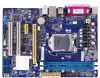
... Channel Memory Configuration 11 Installing a Memory 11 2-3 Install an Expansion Card 13 2-4 Install other Internal Connectors 14 2-5 Jumper 17 Chapter 3 BIOS Setup Enter BIOS Setup 20 Main...21 F-Center...23 Smart BIOS 23 Fox Intelligent Stepping 24 CPU Configuration 25 Performance Tuning 26 Advanced...28 North Bridge 28 ME Subsystem 29 Onboard Device...
... Channel Memory Configuration 11 Installing a Memory 11 2-3 Install an Expansion Card 13 2-4 Install other Internal Connectors 14 2-5 Jumper 17 Chapter 3 BIOS Setup Enter BIOS Setup 20 Main...21 F-Center...23 Smart BIOS 23 Fox Intelligent Stepping 24 CPU Configuration 25 Performance Tuning 26 Advanced...28 North Bridge 28 ME Subsystem 29 Onboard Device...
User manual
Page 15
..., hard drive, etc. The CPU cannot be set the frequency beyond hardware specifications since it does not meet the standard requirements for HT Technology ■ A BIOS that supports HT Technology and has it enabled Install the CPU Locate the alignment keys on the motherboard CPU socket and the notches on the...
..., hard drive, etc. The CPU cannot be set the frequency beyond hardware specifications since it does not meet the standard requirements for HT Technology ■ A BIOS that supports HT Technology and has it enabled Install the CPU Locate the alignment keys on the motherboard CPU socket and the notches on the...
User manual
Page 20
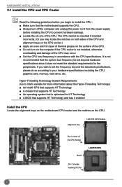
...: Push the latch at the end of the PCI Express x16 slot to make any required BIOS changes for your operating system. After installing all expansion cards, replace the chassis cover. 6. If necessary, go to BIOS Setup to release the card and then pull the card straight up from the slot. 13...
...: Push the latch at the end of the PCI Express x16 slot to make any required BIOS changes for your operating system. After installing all expansion cards, replace the chassis cover. 6. If necessary, go to BIOS Setup to release the card and then pull the card straight up from the slot. 13...
User manual
Page 23
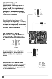
... INTR 1 GND TX+ TXGND RXRX+ GND SATA_1/2/3/4 1 GND POWER SENSE CONTROL CPU_FAN/SYS_FAN1 16 USB 2.0 Connectors: F_USB1/2 These connectors comply with COM1 connector in the BIOS Setup. VCC DD+ GND EMPTY 12 9 10 VCC DD+ GND GND F_USB1/2 Serial ATA 2.0 Connectors: SATA_1/2/3/4 These connectors are used to a security switch on the...
... INTR 1 GND TX+ TXGND RXRX+ GND SATA_1/2/3/4 1 GND POWER SENSE CONTROL CPU_FAN/SYS_FAN1 16 USB 2.0 Connectors: F_USB1/2 These connectors comply with COM1 connector in the BIOS Setup. VCC DD+ GND EMPTY 12 9 10 VCC DD+ GND GND F_USB1/2 Serial ATA 2.0 Connectors: SATA_1/2/3/4 These connectors are used to a security switch on the...
User manual
Page 24
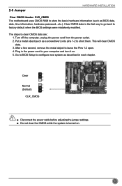
Clear CMOS data is turned on . 5. This will clear CMOS data. 3. CAUTION 17 Go to BIOS Setup to configure new system as described in the power cord to your computer and turn it on . After a few second, remove the metal object ... adjusting the jumper settings. ■ Do not clear the CMOS while the system is the fast way to go back to factory default when the BIOS settings were mistakenly modified. The steps to leave the Pins 1-2 open. 4. 2-5 Jumper HARDWARE INSTALLATION Clear CMOS Header: CLR_CMOS The motherboard uses CMOS RAM to store...
Clear CMOS data is turned on . 5. This will clear CMOS data. 3. CAUTION 17 Go to BIOS Setup to configure new system as described in the power cord to your computer and turn it on . After a few second, remove the metal object ... adjusting the jumper settings. ■ Do not clear the CMOS while the system is the fast way to go back to factory default when the BIOS settings were mistakenly modified. The steps to leave the Pins 1-2 open. 4. 2-5 Jumper HARDWARE INSTALLATION Clear CMOS Header: CLR_CMOS The motherboard uses CMOS RAM to store...
User manual
Page 25
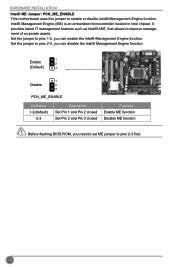
... 2 (Default) 3 1 Disable 2 3 PCH_ME_ENABLE Definition 1-2(default) 2-3 Description Set Pin 1 and Pin 2 closed Set Pin 2 and Pin 3 closed Function Enable ME function Disable ME function Before flashing BIOS ROM, you can enable the Intel® Management Engine function. CAUTION 18 It provides latest IT management features such as Intel® AMT, that allows...
... 2 (Default) 3 1 Disable 2 3 PCH_ME_ENABLE Definition 1-2(default) 2-3 Description Set Pin 1 and Pin 2 closed Set Pin 2 and Pin 3 closed Function Enable ME function Disable ME function Before flashing BIOS ROM, you can enable the Intel® Management Engine function. CAUTION 18 It provides latest IT management features such as Intel® AMT, that allows...
User manual
Page 26
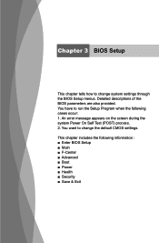
Chapter 3 BIOS Setup This chapter tells how to change the default CMOS settings. An error message appears on the screen during the system Power On Self Test (POST) process. 2. Detailed descriptions of the BIOS parameters are also provided. This chapter includes the following cases occur: 1. You have to change system settings through the BIOS Setup menus. You want to run the Setup Program when the following information : ■ Enter BIOS Setup ■ Main ■ F-Center ■ Advanced ■ Boot ■ Power ■ Health ■ Security ■ Save & Exit
Chapter 3 BIOS Setup This chapter tells how to change the default CMOS settings. An error message appears on the screen during the system Power On Self Test (POST) process. 2. Detailed descriptions of the BIOS parameters are also provided. This chapter includes the following cases occur: 1. You have to change system settings through the BIOS Setup menus. You want to run the Setup Program when the following information : ■ Enter BIOS Setup ■ Main ■ F-Center ■ Advanced ■ Boot ■ Power ■ Health ■ Security ■ Save & Exit
User manual
Page 27
..., trial and error, to enter boot menu" appears at the bottom of your current system. You can save or discard the changes and exit BIOS setup here. 20 It means, if your CPU/System. They all can be responsible for the chipset can be setup through this menu. Security ...values for any damage which resulted from the change fan speeds, and displays temperatures and voltages of your system loading is heavy, set up the BIOS parameters is critical to optimal default may cause problem if you need now is explained below: Main It displays the basic system configuration, such ...
..., trial and error, to enter boot menu" appears at the bottom of your current system. You can save or discard the changes and exit BIOS setup here. 20 It means, if your CPU/System. They all can be responsible for the chipset can be setup through this menu. Security ...values for any damage which resulted from the change fan speeds, and displays temperatures and voltages of your system loading is heavy, set up the BIOS parameters is critical to optimal default may cause problem if you need now is explained below: Main It displays the basic system configuration, such ...
User manual
Page 28
...Security Save & Exit System Date System Time [Fri 04/20/2012] Set the Date. Access Level Model Name ME Version BIOS Version Build Date and Time Administrator H61MXP 8.0.10.1464 C36F1D05 04/20/2012 15:01:45 Halt On [All, but keyboard] CPU Brand Name: Intel(R) Core(...1219. Day-weekday from 1 to 31. Use [ENTER], [TAB] or [SHIFT-TAB] to input the value. User can result in system halt. 21 Main BIOS SETUP Aptio Setup Utility - C opyright (C) 2012 American Megatrends, Inc. Copyright (C) 2012 American Megatrends, Inc. ► System Date format. to input the value. ...
...Security Save & Exit System Date System Time [Fri 04/20/2012] Set the Date. Access Level Model Name ME Version BIOS Version Build Date and Time Administrator H61MXP 8.0.10.1464 C36F1D05 04/20/2012 15:01:45 Halt On [All, but keyboard] CPU Brand Name: Intel(R) Core(...1219. Day-weekday from 1 to 31. Use [ENTER], [TAB] or [SHIFT-TAB] to input the value. User can result in system halt. 21 Main BIOS SETUP Aptio Setup Utility - C opyright (C) 2012 American Megatrends, Inc. Copyright (C) 2012 American Megatrends, Inc. ► System Date format. to input the value. ...

User manual
Page 29
BIOS SETUP [All, but keyboard]: All errors but keyboard can result in your system before powering on. ► MAC Address This item displays the onboard LAN MAC address. 22 The size is depending on how many memory modules are installed in system halt. ► CPU Brand Name It displays the current CPU name. ► Total Memory This item displays the total memory size.
BIOS SETUP [All, but keyboard]: All errors but keyboard can result in your system before powering on. ► MAC Address This item displays the onboard LAN MAC address. 22 The size is depending on how many memory modules are installed in system halt. ► CPU Brand Name It displays the current CPU name. ► Total Memory This item displays the total memory size.
User manual
Page 30
...General Help F2: Previous Values F3: Optimized Defaults F4: Save & Reset ESC: Exit Version 2.14.1219. F-Center BIOS SETUP Aptio Setup Utility - Smart BIOS Aptio Setup Utility - F1: General Help F2: Previous Values F3: Optimized Defaults F4: Save & Exit ESC: ...: Select +/-: Change Opt. Main AFd-vCaenctedr Advanced Boot Power Health Security Save & Exit Fox Control Center Super BIOS Protection Settings Super BIOS Protect [Disabled] ▶ Smart BIOS ▶ Fox Intelligent Stepping ▶ CPU Configuration ▶ Performance Tuning → ←: Select Screen ↑...
...General Help F2: Previous Values F3: Optimized Defaults F4: Save & Reset ESC: Exit Version 2.14.1219. F-Center BIOS SETUP Aptio Setup Utility - Smart BIOS Aptio Setup Utility - F1: General Help F2: Previous Values F3: Optimized Defaults F4: Save & Exit ESC: ...: Select +/-: Change Opt. Main AFd-vCaenctedr Advanced Boot Power Health Security Save & Exit Fox Control Center Super BIOS Protection Settings Super BIOS Protect [Disabled] ▶ Smart BIOS ▶ Fox Intelligent Stepping ▶ CPU Configuration ▶ Performance Tuning → ←: Select Screen ↑...
User manual
Page 31
BIOS SETUP ► Smart Power LED Smart Power LED is a feature built on your computer through smart boot menu. Continue blinking On (1/2sec.), Off (1/2sec.) Stop ...
BIOS SETUP ► Smart Power LED Smart Power LED is a feature built on your computer through smart boot menu. Continue blinking On (1/2sec.), Off (1/2sec.) Stop ...
User manual
Page 32
... run multiple operating systems and applications in independent partitions or "containers." F1: General Help F2: Previous Values F3: Optimized Defaults F4: Save & Reset ESC: Exit BIOS SETUP Version 2.14.1219. Should be displayed only when the CPU is supporting this feature and the setting is used to enable/disable it. ►...
... run multiple operating systems and applications in independent partitions or "containers." F1: General Help F2: Previous Values F3: Optimized Defaults F4: Save & Reset ESC: Exit BIOS SETUP Version 2.14.1219. Should be displayed only when the CPU is supporting this feature and the setting is used to enable/disable it. ►...
User manual
Page 33
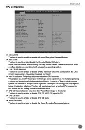
... CPU Configuration ▶ North Bridge Configuration CPU Configuration → ←: Select Screen ↑ ↓: Select Item Enter: Select +/-: Change Opt. BIOS SETUP Performance Tuning Aptio Setup Utility - Configuration database of using XMP timing profile 1. CAUTION Enhanced Intel SpeedStep® technology (EIST) allows the system to... can enable/disable the Turbo mode. There are some system requirements must be met, including CPU, chipset, motherboard, BIOS and operation system. Options: [Automatic], [Manual], [XMP Profile 1], [XMP Profile 2]. [Automatic]-
... CPU Configuration ▶ North Bridge Configuration CPU Configuration → ←: Select Screen ↑ ↓: Select Item Enter: Select +/-: Change Opt. BIOS SETUP Performance Tuning Aptio Setup Utility - Configuration database of using XMP timing profile 1. CAUTION Enhanced Intel SpeedStep® technology (EIST) allows the system to... can enable/disable the Turbo mode. There are some system requirements must be met, including CPU, chipset, motherboard, BIOS and operation system. Options: [Automatic], [Manual], [XMP Profile 1], [XMP Profile 2]. [Automatic]-
User manual
Page 34
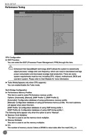
The value that BIOS programs into the memory controller is a function of each DIMM. ► tRP This item allows you to select the row precharge time (in clock cycles). &#... care ratio limit. ► Graphics Voltage(1/256) This item is determined from the supported CAS latencies at given clock frequencies of the target clock frequency. BIOS SETUP asserted depends on the memory clock frequency.
The value that BIOS programs into the memory controller is a function of each DIMM. ► tRP This item allows you to select the row precharge time (in clock cycles). &#... care ratio limit. ► Graphics Voltage(1/256) This item is determined from the supported CAS latencies at given clock frequencies of the target clock frequency. BIOS SETUP asserted depends on the memory clock frequency.
User manual
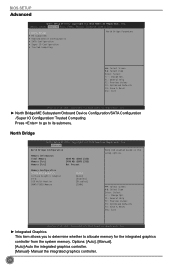
Page 35
... setup options. → ←: Select Screen ↑ ↓: Select Item Enter: Select +/-: Change Opt. Manual the integrated graphics controller. 28 North Bridge Aptio Setup Utility - BIOS SETUP Advanced Aptio Setup Utility - C opyright (C) 2012 American Megatrends, Inc. F1: General Help F2: Previous Values F3: Optimized Defaults F4: Save & Reset ESC: Exit Version...
... setup options. → ←: Select Screen ↑ ↓: Select Item Enter: Select +/-: Change Opt. Manual the integrated graphics controller. 28 North Bridge Aptio Setup Utility - BIOS SETUP Advanced Aptio Setup Utility - C opyright (C) 2012 American Megatrends, Inc. F1: General Help F2: Previous Values F3: Optimized Defaults F4: Save & Reset ESC: Exit Version...
User manual
Page 36
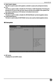
ME Subsystem Aptio Setup Utility - BIOS SETUP ► Initial Graphic Adapter This item is used to select which graphics controller is used as the primary boot device. ► VT-d This item ...
ME Subsystem Aptio Setup Utility - BIOS SETUP ► Initial Graphic Adapter This item is used to select which graphics controller is used as the primary boot device. ► VT-d This item ...
User manual
Page 37
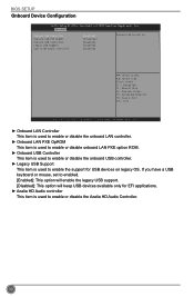
... ↑ ↓: Select Item Enter: Select +/-: Change Opt. F1: General Help F2: Previous Values F3: Optimized Defaults F4: Save & Exit ESC: Exit Version 2.14.1219. BIOS SETUP Onboard Device Configuration Aptio Setup Utility -
... ↑ ↓: Select Item Enter: Select +/-: Change Opt. F1: General Help F2: Previous Values F3: Optimized Defaults F4: Save & Exit ESC: Exit Version 2.14.1219. BIOS SETUP Onboard Device Configuration Aptio Setup Utility -
User manual
Page 38
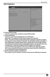
... show the SATA Device information. 31 F1: General Help F2: Previous Values F3: Optimized Defaults F4: Save & Exit ESC: Exit Version 2.14.1219. SATA Configuration BIOS SETUP Aptio Setup Utility -
... show the SATA Device information. 31 F1: General Help F2: Previous Values F3: Optimized Defaults F4: Save & Exit ESC: Exit Version 2.14.1219. SATA Configuration BIOS SETUP Aptio Setup Utility -
User manual
Page 39
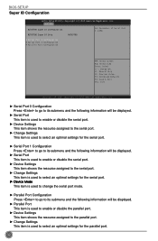
... the parallel port. ► Change Settings This item is used to select an optimal settings for the parallel port. 32 C opyright (C) 2012 American Megatrends, Inc. BIOS SETUP Super IO Configuration Aptio Setup Utility - Advanced NCT6779D Super IO Configuration NCT6779D Super IO Chip NCT6779D Set Parameters of Serial Port 0 (COMA) ▶ Serial...
... the parallel port. ► Change Settings This item is used to select an optimal settings for the parallel port. 32 C opyright (C) 2012 American Megatrends, Inc. BIOS SETUP Super IO Configuration Aptio Setup Utility - Advanced NCT6779D Super IO Configuration NCT6779D Super IO Chip NCT6779D Set Parameters of Serial Port 0 (COMA) ▶ Serial...


