
English Manual
Page 5
... can operate normally when your device. ■ If there is turned off before installing or removing CPU, memory, expansion cards or other peripherals. nections might damage the motherboard. ■ When handling the motherboard, avoid touching any installation steps or have a problem related to the use of your CPU is suggested to high temperature. Also, make sure the power supply AC input voltage setting has been configured to the local standard...
... can operate normally when your device. ■ If there is turned off before installing or removing CPU, memory, expansion cards or other peripherals. nections might damage the motherboard. ■ When handling the motherboard, avoid touching any installation steps or have a problem related to the use of your CPU is suggested to high temperature. Also, make sure the power supply AC input voltage setting has been configured to the local standard...
English Manual
Page 6
... Product Specifications 2 Layout...4 Back Panel Connectors 5 Chapter 2 Hardware Install Install the CPU and CPU Cooler 8 Install the Memory 10 Install an Expansion Card 12 Install other Internal Connectors 13 Jumpers 17 Install driver and utility 18 Chapter 3 BIOS Setup Enter BIOS Setup 21 Main Menu 21 System Information 23 Advanced BIOS Features 25 Core Releaser 26 Fox Central Control Unit 27 Advanced Chipset Features 32 Integrated Peripherals 36 Power Management Setup 40 PC Health Status 42 BIOS Security Features 43 Load Optimal Defaults 44 Save Changes...
... Product Specifications 2 Layout...4 Back Panel Connectors 5 Chapter 2 Hardware Install Install the CPU and CPU Cooler 8 Install the Memory 10 Install an Expansion Card 12 Install other Internal Connectors 13 Jumpers 17 Install driver and utility 18 Chapter 3 BIOS Setup Enter BIOS Setup 21 Main Menu 21 System Information 23 Advanced BIOS Features 25 Core Releaser 26 Fox Central Control Unit 27 Advanced Chipset Features 32 Integrated Peripherals 36 Power Management Setup 40 PC Health Status 42 BIOS Security Features 43 Load Optimal Defaults 44 Save Changes...
English Manual
Page 9
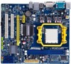
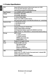
... USB Support hot plug Support up to 12 x USB 2.0 ports (6 rear panel ports, 3 onboard USB headers supporting 6 extra ports) Support USB 2.0 protocol up to 16GB of system memory Dual channel DDR3 1600(oc*)/1333/1066 MHz architecture (oc*: overclocking) Expansion Slots 1 x PCI Express x16 slot 1 x PCI Express x1 slot 2 x PCI slots VGA Integrated ATI RadeonTM HD4250 GPU Support Hybrid Graphic Technology Dual independent displays support with HDMI/DVI and D-Sub Support DirectX 10.1, Shader Model 4.1, Universal Video Decoder (UVD) 2.0 Storage SB710 chipset: - 5 x SATA...
... USB Support hot plug Support up to 12 x USB 2.0 ports (6 rear panel ports, 3 onboard USB headers supporting 6 extra ports) Support USB 2.0 protocol up to 16GB of system memory Dual channel DDR3 1600(oc*)/1333/1066 MHz architecture (oc*: overclocking) Expansion Slots 1 x PCI Express x16 slot 1 x PCI Express x1 slot 2 x PCI slots VGA Integrated ATI RadeonTM HD4250 GPU Support Hybrid Graphic Technology Dual independent displays support with HDMI/DVI and D-Sub Support DirectX 10.1, Shader Model 4.1, Universal Video Decoder (UVD) 2.0 Storage SB710 chipset: - 5 x SATA...

English Manual
Page 10
... 1 x 8-pin ATX 12V power connector 5 x SATA connectors 1 x ESATA connector 1 x IDE connector 3 x USB 2.0 connectors (supporting 6 x USB devices) 1 x CPU fan header (4-pin) 1 x System fan header (4-pin) 1 x NB fan header (4-pin) 1 x Front panel connector 1 x CD_IN connector 1 x Front Audio connector 1 x SPDIF_OUT connector 1 x COM connector 1 x Chassis intrusion alarm header (INTR) 1 x Speaker connector Back Panel 1 x PS/2 Keyboard port Connectors 1 x VGA port 1 x HDMI port 1 x DVI-D port 6 x USB 2.0 ports 1 x RJ-45 LAN port 1 x ESATA Port 8-channel Audio ports Hardware Monitor...
... 1 x 8-pin ATX 12V power connector 5 x SATA connectors 1 x ESATA connector 1 x IDE connector 3 x USB 2.0 connectors (supporting 6 x USB devices) 1 x CPU fan header (4-pin) 1 x System fan header (4-pin) 1 x NB fan header (4-pin) 1 x Front panel connector 1 x CD_IN connector 1 x Front Audio connector 1 x SPDIF_OUT connector 1 x COM connector 1 x Chassis intrusion alarm header (INTR) 1 x Speaker connector Back Panel 1 x PS/2 Keyboard port Connectors 1 x VGA port 1 x HDMI port 1 x DVI-D port 6 x USB 2.0 ports 1 x RJ-45 LAN port 1 x ESATA Port 8-channel Audio ports Hardware Monitor...

English Manual
Page 14
.... CPU Support List: http://www.foxconnsupport.com/cpusupportlist.aspx Memory, VGA Compatibility List: http://www.foxconnsupport.com/complist.aspx This chapter introduces the hardware and software installation process, including the installation of the CPU, memory, power supply, slots, pin headers and the mounting of these modules. This chapter includes the following information : ■ Install the CPU and CPU Cooler ■ Install the Memory ■ Install an Expansion Card ■ Install other Internal Connectors ■ Jumpers ■ Install driver and utility Please...
.... CPU Support List: http://www.foxconnsupport.com/cpusupportlist.aspx Memory, VGA Compatibility List: http://www.foxconnsupport.com/complist.aspx This chapter introduces the hardware and software installation process, including the installation of the CPU, memory, power supply, slots, pin headers and the mounting of these modules. This chapter includes the following information : ■ Install the CPU and CPU Cooler ■ Install the Memory ■ Install an Expansion Card ■ Install other Internal Connectors ■ Jumpers ■ Install driver and utility Please...
English Manual
Page 19
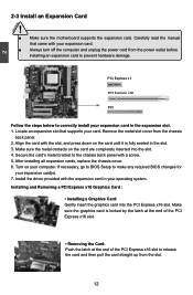
... motherboard supports the expansion card. Install the driver provided with the slot, and press down on the card are completely inserted into the PCI Express x16 slot. Carefully read the manual that supports your computer. If necessary, go to BIOS Setup to release the card and then pull the card straight up from the chassis back panel. 2. Installing and Removing a PCI Express x16 Graphics Card : • Installing a Graphics Card: Gently insert the graphics card into the slot. 4. After installing all expansion cards, replace...
... motherboard supports the expansion card. Install the driver provided with the slot, and press down on the card are completely inserted into the PCI Express x16 slot. Carefully read the manual that supports your computer. If necessary, go to BIOS Setup to release the card and then pull the card straight up from the chassis back panel. 2. Installing and Removing a PCI Express x16 Graphics Card : • Installing a Graphics Card: Gently insert the graphics card into the slot. 4. After installing all expansion cards, replace...

English Manual
Page 21
... the switch is blinking; This 2-pin connector is used to be turned on . Front Panel Connector : FP1 This motherboard includes one connector for connecting the front panel switch and LED Indicators. Reset Switch (RESET-SW) Attach the connector to the picture on the front panel of the hard disks. We recommend you need to align the ATX power connector according to the Reset switch on the right. If you are using a 4-pin power supply, you using the power supply button. 12 + + HDD-LED - The Power LED indicates...
... the switch is blinking; This 2-pin connector is used to be turned on . Front Panel Connector : FP1 This motherboard includes one connector for connecting the front panel switch and LED Indicators. Reset Switch (RESET-SW) Attach the connector to the picture on the front panel of the hard disks. We recommend you need to align the ATX power connector according to the Reset switch on the right. If you are using a 4-pin power supply, you using the power supply button. 12 + + HDD-LED - The Power LED indicates...
English Manual
Page 24
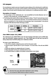
... system as BIOS data, date, time information, hardware password...etc.). The shorting can prevent hazardous ESD (Electrical Static Discharge) problem. The steps to it. Return the setting to its original with pins 2-3 closed Clear CMOS Jumper: CLR_CMOS The motherboard uses CMOS RAM to factory default when the BIOS settings were mistakenly modified. Normal 1 2 (Default) 3 CLR_CMOS ■ Disconnect the power cable before adjusting the jumper settings. ■ Do not clear the CMOS while the...
... system as BIOS data, date, time information, hardware password...etc.). The shorting can prevent hazardous ESD (Electrical Static Discharge) problem. The steps to it. Return the setting to its original with pins 2-3 closed Clear CMOS Jumper: CLR_CMOS The motherboard uses CMOS RAM to factory default when the BIOS settings were mistakenly modified. Normal 1 2 (Default) 3 CLR_CMOS ■ Disconnect the power cable before adjusting the jumper settings. ■ Do not clear the CMOS while the...
English Manual
Page 25
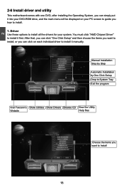
... "AMD Chipset Driver" to install it manually. Driver Use these options to install all the drivers for your PC screen to guide you how to install. 1. 2 2-6 Install driver and utility This motherboard comes with one DVD, after installing the Operating System, you can click on your system. After that, you can click "One Click Setup" and then choose the items you can simply put it into your DVD-ROM drive, and the main menu will...
... "AMD Chipset Driver" to install it manually. Driver Use these options to install all the drivers for your PC screen to guide you how to install. 1. 2 2-6 Install driver and utility This motherboard comes with one DVD, after installing the Operating System, you can click on your system. After that, you can click "One Click Setup" and then choose the items you can simply put it into your DVD-ROM drive, and the main menu will...
English Manual
Page 28
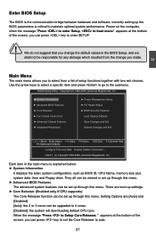
... software, correctly setting up the BIOS parameters is explained below: ► System Information It displays the basic system configuration, such as BIOS ID, CPU Name, memory size plus system date, time and Floppy drive. Power on the computer, when the message "Press to enter Setup, to maintain optimal system performance. We do not suggest that you to 4 cores. [Disabled]: the system will downloading default CPU core. Use the arrow keys to select a specific...
... software, correctly setting up the BIOS parameters is explained below: ► System Information It displays the basic system configuration, such as BIOS ID, CPU Name, memory size plus system date, time and Floppy drive. Power on the computer, when the message "Press to enter Setup, to maintain optimal system performance. We do not suggest that you to 4 cores. [Disabled]: the system will downloading default CPU core. Use the arrow keys to select a specific...
English Manual
Page 30
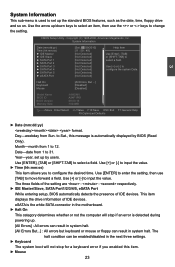
... BIOS (Read Only). Use [+] or [-] to [Not Detected] configure the system Date. [Not Detected] [Not Detected] Halt On Keyboard Mouse [All Errors, But ...] [Disabled] [Disabled] Model Name BIOS ID BIOS Version Memory Size :A88GMV :A34F1P01 :08.00.16 :1024MB Move Enter:Select +/-/:Value F10:Save ESC:Exit F1:General Help F9:Optimized Defaults 3 ► Date (mm:dd:yy) format. eSATA is the white SATA connector in the motherboard...
... BIOS (Read Only). Use [+] or [-] to [Not Detected] configure the system Date. [Not Detected] [Not Detected] Halt On Keyboard Mouse [All Errors, But ...] [Disabled] [Disabled] Model Name BIOS ID BIOS Version Memory Size :A88GMV :A34F1P01 :08.00.16 :1024MB Move Enter:Select +/-/:Value F10:Save ESC:Exit F1:General Help F9:Optimized Defaults 3 ► Date (mm:dd:yy) format. eSATA is the white SATA connector in the motherboard...
English Manual
Page 33
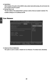
... Move Enter:Select +/-/:Value F10:Save ESC:Exit F1:General Help F9:Optimized Defaults ► Advanced Clock Calibration This option is used to boot the system. ► Bootup Num-Lock This item defines if the keyboard Num Lock key is active when your system is started. Copyright (C) 1985-2006, American Megatrends, Inc. The available settings are: On (default) and Off. Core Releaser CMOS Setup Utility...
... Move Enter:Select +/-/:Value F10:Save ESC:Exit F1:General Help F9:Optimized Defaults ► Advanced Clock Calibration This option is used to boot the system. ► Bootup Num-Lock This item defines if the keyboard Num Lock key is active when your system is started. Copyright (C) 1985-2006, American Megatrends, Inc. The available settings are: On (default) and Off. Core Releaser CMOS Setup Utility...
English Manual
Page 36
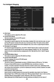
... "Memory Speed Adjust" item. Fox Intelligent Stepping CMOS Setup Utility - The Serial Presence Detect (SPD) device is used to adjust the CPU Clock Ratio. Copyright (C) 1985-2006, American Megatrends, Inc. Multiply CPU clock with the CPUNB HT Speed setting. ► CPU-NB Multiplier Adjust This option is used to adjust the CPU-NB Clock Ratio. ► Current CPU-NB Speed This item displays the current CPU-NB speed. ► Memory Speed Mode This item is used to enable/disable provision...
... "Memory Speed Adjust" item. Fox Intelligent Stepping CMOS Setup Utility - The Serial Presence Detect (SPD) device is used to adjust the CPU Clock Ratio. Copyright (C) 1985-2006, American Megatrends, Inc. Multiply CPU clock with the CPUNB HT Speed setting. ► CPU-NB Multiplier Adjust This option is used to adjust the CPU-NB Clock Ratio. ► Current CPU-NB Speed This item displays the current CPU-NB speed. ► Memory Speed Mode This item is used to enable/disable provision...
English Manual
Page 40
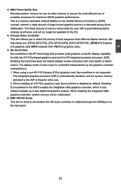
... Express x16 graphics card; When using a non-ATI PCI Express (PCIe) graphics card, SurroundView is the ATI technology that provides multi-graphics controller display capability for both the ATI PCIe-based graphics card and the ATI integrated graphics processor (IGP). PCI-PCI graphics card.) ► Surround View SurroundView is not supported. The display mode of page-locked graphics memory is allocated during driver initialization. When installing an ATI PCIe graphics card, SurroundView is enabled through the HDMI port on the rear panel. 33 Enabling SurroundView in the BIOS enables...
... Express x16 graphics card; When using a non-ATI PCI Express (PCIe) graphics card, SurroundView is the ATI technology that provides multi-graphics controller display capability for both the ATI PCIe-based graphics card and the ATI integrated graphics processor (IGP). PCI-PCI graphics card.) ► Surround View SurroundView is not supported. The display mode of page-locked graphics memory is allocated during driver initialization. When installing an ATI PCIe graphics card, SurroundView is enabled through the HDMI port on the rear panel. 33 Enabling SurroundView in the BIOS enables...

English Manual
Page 43
...[Press Enter] [Press Enter] Configure the IDE [Enabled] device(s). [Disabled] [Enabled] Move Enter:Select +/-/:Value F10:Save ESC:Exit F1:General Help F9:Optimized Defaults ► IDE Configuration / USB Configuration / SuperIO Configuration Press to go to relative submenu. ► OnBoard LAN This item is used to enable or disable the onboard LAN controller. ► OnBoard LAN Boot ROM This item is used to enable or disable the HD Audio Controller. 36 A LAN boot ROM lets you can enable a client PC system on the network. By installing a boot ROM in the network board...
...[Press Enter] [Press Enter] Configure the IDE [Enabled] device(s). [Disabled] [Enabled] Move Enter:Select +/-/:Value F10:Save ESC:Exit F1:General Help F9:Optimized Defaults ► IDE Configuration / USB Configuration / SuperIO Configuration Press to go to relative submenu. ► OnBoard LAN This item is used to enable or disable the onboard LAN controller. ► OnBoard LAN Boot ROM This item is used to enable or disable the HD Audio Controller. 36 A LAN boot ROM lets you can enable a client PC system on the network. By installing a boot ROM in the network board...

English Manual
Page 44
...used to support native IDE mode. [RAID] - The specification includes a description of your SATA drives must also support AHCI. [AHCI] - 3 IDE Configuration CMOS Setup Utility - Copyright (C) 1985-2006, American Megatrends, Inc. IDE Configuration IDE Configuration Help Item OnChip SATA Channel [Ena bled] Disabled OnChip SATA Type [Native IDE] I Enabled SATA IDE Combined Mode [Enabled] Move Enter:Select +/-/:Value F10:Save ESC:Exit F1:General Help F9:Optimized Defaults ► OnChip SATA Channel...
...used to support native IDE mode. [RAID] - The specification includes a description of your SATA drives must also support AHCI. [AHCI] - 3 IDE Configuration CMOS Setup Utility - Copyright (C) 1985-2006, American Megatrends, Inc. IDE Configuration IDE Configuration Help Item OnChip SATA Channel [Ena bled] Disabled OnChip SATA Type [Native IDE] I Enabled SATA IDE Combined Mode [Enabled] Move Enter:Select +/-/:Value F10:Save ESC:Exit F1:General Help F9:Optimized Defaults ► OnChip SATA Channel...
English Manual
Page 47
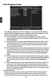
... Item Energy-using Products [Enabled] Resume by LAN [Disabled] Select the ACPI Resume by PCIE Card [Disabled] System Suspend. The S2 sleeping state is a low wake latency sleeping state. The S3 sleeping state is maintained. (also called Power On Suspend) S2 - When you select "S1 (POS)" mode, the power is lost in the "soft" off all devices. Resume by USB Devices [Disabled] Resume by PS2 Keyboard [Disabled] Resume by ACPI. Power Management Setup CMOS Setup Utility - Copyright...
... Item Energy-using Products [Enabled] Resume by LAN [Disabled] Select the ACPI Resume by PCIE Card [Disabled] System Suspend. The S2 sleeping state is a low wake latency sleeping state. The S3 sleeping state is maintained. (also called Power On Suspend) S2 - When you select "S1 (POS)" mode, the power is lost in the "soft" off all devices. Resume by USB Devices [Disabled] Resume by PS2 Keyboard [Disabled] Resume by ACPI. Power Management Setup CMOS Setup Utility - Copyright...
English Manual
Page 50
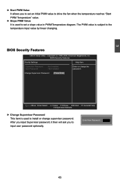
...:Optimized Defaults ► Change Supervisor Password This item is used to set a slope value in PWM/Temperature diagram. Enter New Password : 43 Copyright (C) 1985-2006, American Megatrends, Inc. BIOS Security Features CMOS Setup Utility - BIOS Security Features Scurity Settings Help Item Supervisor Password : Not Installed Enter or change supervisor password. After you input Supervisor password, it then will ask you to set an initial PWM value to drive the fan when the temperature reaches "Start PWM Temperature...
...:Optimized Defaults ► Change Supervisor Password This item is used to set a slope value in PWM/Temperature diagram. Enter New Password : 43 Copyright (C) 1985-2006, American Megatrends, Inc. BIOS Security Features CMOS Setup Utility - BIOS Security Features Scurity Settings Help Item Supervisor Password : Not Installed Enter or change supervisor password. After you input Supervisor password, it then will ask you to set an initial PWM value to drive the fan when the temperature reaches "Start PWM Temperature...
English Manual
Page 54
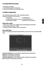
... enter the main menu of the Option ROM Utility. Hardware and software you may need here : ■ A floppy drive ■ A DVD-ROM drive ■ A floppy disk(Or USB disk for Vista) ■ A motherboard driver CD ■ Several SATA hard disks ■ Windows XP or Vista Install CD RAID Enable in BIOS 1. Controller Configuration: To view the SATA controller configuration by pressing [1]. Set the "OnChip SATA Type" to "RAID". 3. Shut down your computer, enter the BIOS setup by pressing [Del] key during POST to save the setting, then PC will reboot itself. Install SATA hard...
... enter the main menu of the Option ROM Utility. Hardware and software you may need here : ■ A floppy drive ■ A DVD-ROM drive ■ A floppy disk(Or USB disk for Vista) ■ A motherboard driver CD ■ Several SATA hard disks ■ Windows XP or Vista Install CD RAID Enable in BIOS 1. Controller Configuration: To view the SATA controller configuration by pressing [1]. Set the "OnChip SATA Type" to "RAID". 3. Shut down your computer, enter the BIOS setup by pressing [Del] key during POST to save the setting, then PC will reboot itself. Install SATA hard...
English Manual
Page 56
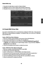
... floppy disk into the floppy disk drive/USB port. 3. Option ROM Utility (c) 2008 Advanced Micro Devices, Inc. [ View[ DLeDfinDeeLfinDitMionenMue]nu ] LD No RAID Mode Total Drv Capacity(MB) Status LD 1 RAID 0 2 XXXXX Functional Stripe Block: 64 KB Cache Mode: WriteThru [ Drives Assignment ] Channel :ID Drive Model Compatibilities Capacity(GB) 1 :Mas XXXXXXXXXXX SATA XG XX.XX 2 :Mas XXXXXXXXXXX SATA XG XX.XX Press Ctrl-Y to create a RAID driver disk when the prompt menu appears. 6. or press any key...
... floppy disk into the floppy disk drive/USB port. 3. Option ROM Utility (c) 2008 Advanced Micro Devices, Inc. [ View[ DLeDfinDeeLfinDitMionenMue]nu ] LD No RAID Mode Total Drv Capacity(MB) Status LD 1 RAID 0 2 XXXXX Functional Stripe Block: 64 KB Cache Mode: WriteThru [ Drives Assignment ] Channel :ID Drive Model Compatibilities Capacity(GB) 1 :Mas XXXXXXXXXXX SATA XG XX.XX 2 :Mas XXXXXXXXXXX SATA XG XX.XX Press Ctrl-Y to create a RAID driver disk when the prompt menu appears. 6. or press any key...


