English Manual.
Page 6
...Expansion Card 12 Install other Internal Connectors 13 Jumpers 17 Install driver and utility 19 Chapter 3 BIOS Setup Enter BIOS Setup 22 Main Menu 22 System Information 24 Advanced BIOS Features 26 Core Releaser 28 Fox Central Control Unit 29 Advanced Chipset Features 32 Integrated Peripherals ...35 Power Management Setup 39 PC Health Status 41 BIOS Security Features 42 Load Optimal Defaults 43 Save & Exit Setup 43 Exit Without Saving 43 Chapter 4 RAID Configuration RAID Introduction 45 Install ...
...Expansion Card 12 Install other Internal Connectors 13 Jumpers 17 Install driver and utility 19 Chapter 3 BIOS Setup Enter BIOS Setup 22 Main Menu 22 System Information 24 Advanced BIOS Features 26 Core Releaser 28 Fox Central Control Unit 29 Advanced Chipset Features 32 Integrated Peripherals ...35 Power Management Setup 39 PC Health Status 41 BIOS Security Features 42 Load Optimal Defaults 43 Save & Exit Setup 43 Exit Without Saving 43 Chapter 4 RAID Configuration RAID Introduction 45 Install ...

English Manual.
Page 19
... • Removing the Card: Push the latch at the end of the PCI Express x16 slot to prevent hardware damage. If necessary, go to BIOS Setup to the chassis back panel with your computer. Locate an expansion slot that came with a screw. 5. Align the card with the expansion card in... Always turn off the computer and unplug the power cord from the chassis back panel. 2. Secure the card's metal bracket to make any required BIOS changes for your expansion card in the slot. 3. Carefully read the manual that supports your operating system. Make sure the metal contacts on the ...
... • Removing the Card: Push the latch at the end of the PCI Express x16 slot to prevent hardware damage. If necessary, go to BIOS Setup to the chassis back panel with your computer. Locate an expansion slot that came with a screw. 5. Align the card with the expansion card in... Always turn off the computer and unplug the power cord from the chassis back panel. 2. Secure the card's metal bracket to make any required BIOS changes for your expansion card in the slot. 3. Carefully read the manual that supports your operating system. Make sure the metal contacts on the ...
English Manual.
Page 23
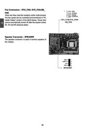
2 Fan Connectors : CPU_FAN, SYS_FAN,NB_ FAN There are three main fan headers on this motherboard. Speaker Connector : SPEAKER The speaker connector is used to connect speaker of the BIOS Setup. These fans can be automatically turned off after the system enters S3, S4 and S5 sleeping states. The fan speed can be controlled and monitored in "PC Health Status" section of the chassis. 1 GND POWER SENSE CONTROL CPU_FAN/SYS_FAN/ NB_FAN SPKJ 1 EMPTY 2 NC 3 SPKJ 4 SPEAKER 16
2 Fan Connectors : CPU_FAN, SYS_FAN,NB_ FAN There are three main fan headers on this motherboard. Speaker Connector : SPEAKER The speaker connector is used to connect speaker of the BIOS Setup. These fans can be automatically turned off after the system enters S3, S4 and S5 sleeping states. The fan speed can be controlled and monitored in "PC Health Status" section of the chassis. 1 GND POWER SENSE CONTROL CPU_FAN/SYS_FAN/ NB_FAN SPKJ 1 EMPTY 2 NC 3 SPKJ 4 SPEAKER 16

English Manual.
Page 24
... the power cord from pins 2-3, put it onto pins 1-2 to factory default when the BIOS settings were mistakenly modified. This section explains how to store the basic hardware information (such as BIOS data, date, time information, hardware password...etc.). However, in this manual, pin 1...Closed" means placing a jumper cap on the two pins to configure new system as "1". 2. Description of the jumper settings. Go to BIOS Setup to temporarily short them . Users should read the following table explains different types of Jumpers 1. Return the setting to modifying any jumper ...
... the power cord from pins 2-3, put it onto pins 1-2 to factory default when the BIOS settings were mistakenly modified. This section explains how to store the basic hardware information (such as BIOS data, date, time information, hardware password...etc.). However, in this manual, pin 1...Closed" means placing a jumper cap on the two pins to configure new system as "1". 2. Description of the jumper settings. Go to BIOS Setup to temporarily short them . Users should read the following table explains different types of Jumpers 1. Return the setting to modifying any jumper ...

English Manual.
Page 25
... USB port; At the same time, a corresponding setting must not exceed the power supply capability (+5VSB) whether under normal condition or in BIOS as below: Set "CMOS Setup" -> "Power Management Setup" -> "USB Wake Up From S3" to "Enabled". 1 +5V 2 (Default) 3 1 +5VSB 2 3 USBPWR1/ USBPWR2/ USBPWR3/ USBPWR4 ! ■ USBPWR2/ USBPWR3 is for the internal USB...
... USB port; At the same time, a corresponding setting must not exceed the power supply capability (+5VSB) whether under normal condition or in BIOS as below: Set "CMOS Setup" -> "Power Management Setup" -> "USB Wake Up From S3" to "Enabled". 1 +5V 2 (Default) 3 1 +5VSB 2 3 USBPWR1/ USBPWR2/ USBPWR3/ USBPWR4 ! ■ USBPWR2/ USBPWR3 is for the internal USB...

English Manual.
Page 28
... includes the following cases occur: 1. We do not guarantee the content of the BIOS parameters are also provided. You have to run the Setup Program when the following information : ■ Enter BIOS Setup ■ Main Menu ■ System Information ■ Advanced BIOS Features ■ Core releaser ■ Fox Central Control Unit ■ Advanced Chipset Features...
... includes the following cases occur: 1. We do not guarantee the content of the BIOS parameters are also provided. You have to run the Setup Program when the following information : ■ Enter BIOS Setup ■ Main Menu ■ System Information ■ Advanced BIOS Features ■ Core releaser ■ Fox Central Control Unit ■ Advanced Chipset Features...

English Manual.
Page 29
... The advanced system features can press key to set up through this menu. Display System Information... Each item in the BIOS Setup, and we shall not be upgraded to auto. 22 Setting Options are boot up settings. ► Core Releaser (Enabled only if...you change the default values in the main menu is critical to maintain optimal system performance. Enter BIOS Setup The BIOS is the communication bridge between hardware and software, correctly setting up the BIOS parameters is explained below: ► System Information It displays the basic system configuration, such as...
... The advanced system features can press key to set up through this menu. Display System Information... Each item in the BIOS Setup, and we shall not be upgraded to auto. 22 Setting Options are boot up settings. ► Core Releaser (Enabled only if...you change the default values in the main menu is critical to maintain optimal system performance. Enter BIOS Setup The BIOS is the communication bridge between hardware and software, correctly setting up the BIOS parameters is explained below: ► System Information It displays the basic system configuration, such as...

English Manual.
Page 30
... Setup Save setting values to read/change Fan speeds, and displays temperatures and voltages of your computer. CAUTION 3 ! If system halt or PC can not enter the Operating System, Please press and hold the Power Button until the PC powers off and restart your CPU/System. ► BIOS .... ► Integrated Peripherals All onboard peripherals can not be upgraded to prevent unauthorized use of your PC. You need clear CMOS or enter BIOS manual to set disable to load default. ► Fox Central Control Unit Some special proprietary features (such as Serial I /O devices such as...
... Setup Save setting values to read/change Fan speeds, and displays temperatures and voltages of your computer. CAUTION 3 ! If system halt or PC can not enter the Operating System, Please press and hold the Power Button until the PC powers off and restart your CPU/System. ► BIOS .... ► Integrated Peripherals All onboard peripherals can not be upgraded to prevent unauthorized use of your PC. You need clear CMOS or enter BIOS manual to set disable to load default. ► Fox Central Control Unit Some special proprietary features (such as Serial I /O devices such as...

English Manual.
Page 31
... configure system Date. [Not Detected] [Not Detected] Halt On Keyboard Mouse [All Errors But ...] [Disabled] [Disabled] Model Name BIOS ID BIOS Version Memory Size :A74GA :A22F1P02 :08.00.15 :1024MB Move Enter:Select +/-/:Value F10:Save ESC:Exit F1:General Help F9:Optimized Defaults 3 ► ... three fields of the setting are : : respectively. ► IDE Master/Slave, SATA1#/SATA2#/SATA3#/SATA4#/SATA5#/SATA6# While entering setup, BIOS automatically detects the presence of IDE devices. ► Halt On This category determines whether or not the computer will not stop if...
... configure system Date. [Not Detected] [Not Detected] Halt On Keyboard Mouse [All Errors But ...] [Disabled] [Disabled] Model Name BIOS ID BIOS Version Memory Size :A74GA :A22F1P02 :08.00.15 :1024MB Move Enter:Select +/-/:Value F10:Save ESC:Exit F1:General Help F9:Optimized Defaults 3 ► ... three fields of the setting are : : respectively. ► IDE Master/Slave, SATA1#/SATA2#/SATA3#/SATA4#/SATA5#/SATA6# While entering setup, BIOS automatically detects the presence of IDE devices. ► Halt On This category determines whether or not the computer will not stop if...

English Manual.
Page 33
... to enable MPS 1.4 support if you start facing problems like stuttering sound or a less responsive system, reduce the latency. MPS 1.1 was the original specification. Advanced BIOS Features IDE Detect Time Out [5] Help Item MPS Revision [1.1] PCI Latency Timer [64] Select the time out Quiet Boot [Enabled] value for detecting Quick Boot... to wait longer before another takes over the set value, the system will use of the bus. Higher values will have to make use . Advanced BIOS Features CMOS Setup Utility - If your operating system comes with a PCI bridge.
... to enable MPS 1.4 support if you start facing problems like stuttering sound or a less responsive system, reduce the latency. MPS 1.1 was the original specification. Advanced BIOS Features IDE Detect Time Out [5] Help Item MPS Revision [1.1] PCI Latency Timer [64] Select the time out Quiet Boot [Enabled] value for detecting Quick Boot... to wait longer before another takes over the set value, the system will use of the bus. Higher values will have to make use . Advanced BIOS Features CMOS Setup Utility - If your operating system comes with a PCI bridge.
English Manual.
Page 36
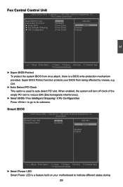
... (C) 1985-2006, American Megatrends, Inc. CIH. ► Auto Detect PCI Clock This option is a feature built on your BIOS from virus attack, there is a BIOS write-protection mechanism provided. When enabled, the system will turn off clock of the empty PCI slot to reduce EMI (Electromagnetic Interference...] Disabled [Press Enter] Enabled 3 Move Enter:Select +/-/:Value F10:Save ESC:Exit F1:General Help F9:Optimized Defaults ► Super BIOS Protect To protect the system BIOS from being affected by viruses, e.g. Smart BIOS CMOS Setup Utility - Fox Central Control Unit CMOS...
... (C) 1985-2006, American Megatrends, Inc. CIH. ► Auto Detect PCI Clock This option is a feature built on your BIOS from virus attack, there is a BIOS write-protection mechanism provided. When enabled, the system will turn off clock of the empty PCI slot to reduce EMI (Electromagnetic Interference...] Disabled [Press Enter] Enabled 3 Move Enter:Select +/-/:Value F10:Save ESC:Exit F1:General Help F9:Optimized Defaults ► Super BIOS Protect To protect the system BIOS from being affected by viruses, e.g. Smart BIOS CMOS Setup Utility - Fox Central Control Unit CMOS...

English Manual.
Page 40
...DCT channels A and B can be ganged as two completely independent 64-bit channels (both DCTs programmed identically. Memory Configuration CMOS Setup Utility - Memory Configuration Memory Configuration Help Item DCT Unganged Mode [Always] This allows selection of each DCT in order. 33 ... a logical pair to access memory. When installing an ATI PCIe graphics card, SurroundView is freed for DRAM Controller. which in the BIOS enables the integrated graphics. Unganged channels ■ DCT channels A and B operate as a single logical 128-bit DIMM. ■...
...DCT channels A and B can be ganged as two completely independent 64-bit channels (both DCTs programmed identically. Memory Configuration CMOS Setup Utility - Memory Configuration Memory Configuration Help Item DCT Unganged Mode [Always] This allows selection of each DCT in order. 33 ... a logical pair to access memory. When installing an ATI PCIe graphics card, SurroundView is freed for DRAM Controller. which in the BIOS enables the integrated graphics. Unganged channels ■ DCT channels A and B operate as a single logical 128-bit DIMM. ■...

English Manual.
Page 41
... [Both] will appear only in order, you also can configure the timings manually. Copyright (C) 1985-2006, American Megatrends, Inc. Settings are enabled in unganged mode, BIOS must initialize the frequency of each DCT in AM2+ or AM3 CPU. 34 3 DRAM Timing Configuration CMOS...
... [Both] will appear only in order, you also can configure the timings manually. Copyright (C) 1985-2006, American Megatrends, Inc. Settings are enabled in unganged mode, BIOS must initialize the frequency of each DCT in AM2+ or AM3 CPU. 34 3 DRAM Timing Configuration CMOS...

English Manual.
Page 45
3 SuperIO Configuration CMOS Setup Utility - Copyright (C) 1985-2006, American Megatrends, Inc. SuperIO Configuration SuperIO Configuration Help Item Serial Port1 Address Serial Port1 Mode Parallel Port Address Parallel Port Mode Parallel Port IRQ [3F8/IRQ4] Allows BIOS to Select [Normal] Serial Port 1 Base adress. [378] [Normal] [IRQ7] Move Enter:Select +/-/:Value F10:Save ESC...
3 SuperIO Configuration CMOS Setup Utility - Copyright (C) 1985-2006, American Megatrends, Inc. SuperIO Configuration SuperIO Configuration Help Item Serial Port1 Address Serial Port1 Mode Parallel Port Address Parallel Port Mode Parallel Port IRQ [3F8/IRQ4] Allows BIOS to Select [Normal] Serial Port 1 Base adress. [378] [Normal] [IRQ7] Move Enter:Select +/-/:Value F10:Save ESC...
English Manual.
Page 46
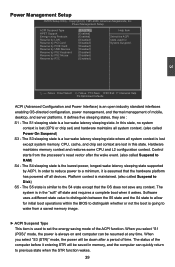
...supported by RTC [S3 (STR)] Help Item [Enabled] [Enabled] Select the ACPI [Disabled] state used for initial boot operations within the BIOS to distinguish whether or not the boot is going to wake from the processor's reset vector after a period of mobile, desktop, and server...computer can be down after the wake event. (also called Power On Suspend) S3 - Power Management Setup CMOS Setup Utility - The status of the ACPI function. Power Management Setup ACPI Suspend Type HPET Support Energy-using Products Resume by LAN Resume by PCI Card Resume by PCIE...
...supported by RTC [S3 (STR)] Help Item [Enabled] [Enabled] Select the ACPI [Disabled] state used for initial boot operations within the BIOS to distinguish whether or not the boot is going to wake from the processor's reset vector after a period of mobile, desktop, and server...computer can be down after the wake event. (also called Power On Suspend) S3 - Power Management Setup CMOS Setup Utility - The status of the ACPI function. Power Management Setup ACPI Suspend Type HPET Support Energy-using Products Resume by LAN Resume by PCI Card Resume by PCIE...
English Manual.
Page 49
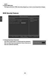
... Security Settings Help Item Supervisor Password : Not Installed User Password : Not Installed Change Supervisor Password [Press Enter] Enter or change supervisor password. BIOS Security Features CMOS Setup Utility - Move Enter:Select +/-/:Value F10:Save ESC:Exit F1:General Help F9:Optimized Defaults ► Change Supervisor Password This item is used to input...
... Security Settings Help Item Supervisor Password : Not Installed User Password : Not Installed Change Supervisor Password [Press Enter] Enter or change supervisor password. BIOS Security Features CMOS Setup Utility - Move Enter:Select +/-/:Value F10:Save ESC:Exit F1:General Help F9:Optimized Defaults ► Change Supervisor Password This item is used to input...

English Manual.
Page 50
...devices (for example, too many expansion cards were installed), the system might fail to work. Discard changes and exit setup? [OK] [Cancel] 43 Save configuration changes and exit setup? [OK] [Cancel] Discard Changes and Exit If you select this option and press Enter, it will pop ...be set the optimal performance parameters of system to improve the performances of system components. Always load the Optimal defaults after updating the BIOS or after clearing the CMOS values. Select this option and press , a message will be supported by your changes to CMOS and ...
...devices (for example, too many expansion cards were installed), the system might fail to work. Discard changes and exit setup? [OK] [Cancel] 43 Save configuration changes and exit setup? [OK] [Cancel] Discard Changes and Exit If you select this option and press Enter, it will pop ...be set the optimal performance parameters of system to improve the performances of system components. Always load the Optimal defaults after updating the BIOS or after clearing the CMOS values. Select this option and press , a message will be supported by your changes to CMOS and ...

English Manual.
Page 51
Existing Windows XP (or Vista) system with new RAID built as data storage. Installing a new Windows XP (or Vista) in this chapter are for reference only, please refer to the practical screen. This chapter will cover two topics : ■ Creating a Bootable Array - It includes the following information : ■ RAID Introduction ■ Install SATA Hard Disks ■ RAID Configuration ■ Create RAID Driver Disk ■ Install Windows OS The RAID BIOS Setup pictures shown in a brand new RAID system. ■ Creating a Non-Bootable Array -
Existing Windows XP (or Vista) system with new RAID built as data storage. Installing a new Windows XP (or Vista) in this chapter are for reference only, please refer to the practical screen. This chapter will cover two topics : ■ Creating a Bootable Array - It includes the following information : ■ RAID Introduction ■ Install SATA Hard Disks ■ RAID Configuration ■ Create RAID Driver Disk ■ Install Windows OS The RAID BIOS Setup pictures shown in a brand new RAID system. ■ Creating a Non-Bootable Array -

English Manual.
Page 53
...USB disk for Vista) ■ A motherboard driver CD ■ Several SATA hard disks ■ Windows XP or Vista Install CD RAID Enable in BIOS 1. Set the "OnChip SATA Type" to Select Option [ESC] Exit View Drive Assignment: To view the disk drive assignment status by pressing [1]. ... [Ctrl-F] key during POST. 2. Define LD: To Create RAID by pressing [4]. 4 4-2 Install SATA Hard Disks 1. Shut down your computer, enter the BIOS setup by pressing [3]. Exit: Press [Esc] to enter the main menu of the Option ROM Utility. Boot up your computer. 2. Install SATA hard disks into ...
...USB disk for Vista) ■ A motherboard driver CD ■ Several SATA hard disks ■ Windows XP or Vista Install CD RAID Enable in BIOS 1. Set the "OnChip SATA Type" to Select Option [ESC] Exit View Drive Assignment: To view the disk drive assignment status by pressing [1]. ... [Ctrl-F] key during POST. 2. Define LD: To Create RAID by pressing [4]. 4 4-2 Install SATA Hard Disks 1. Shut down your computer, enter the BIOS setup by pressing [3]. Exit: Press [Esc] to enter the main menu of the Option ROM Utility. Boot up your computer. 2. Install SATA hard disks into ...


