
Operation Manual
Page 5
...Fig. A2-1 Parallel Interface Timing ........ 84 85 89 -iv- A1-2 Driver Circuit Diagram ..... Fig. 41 Alignment of Side Edges 32 Fig. 42 Form Position Setting Mark 32 Fig. 43 Print Area 3 2 Fig. 44 Setting of Cut Paper Sheet 33 Fig. 45 Printer with Cut Paper Sheet Set Completely 33 Fig. 46 Gap Adjustment... Feed Knob 41 Fig. 51 Loosening All 4 Screws 41 Fig. 52 Pulling Out Wires Hooked to Control Panel 42 Fig. 53 Construction of Type II Printer 43 Fig. 54 Location of DIP Switches 4 4 Fig. 55 Setting DIP Switches 4 4 Fig. 56 Setting Amount of Line Spacing 48 Fig. 57 Setting Form...
...Fig. A2-1 Parallel Interface Timing ........ 84 85 89 -iv- A1-2 Driver Circuit Diagram ..... Fig. 41 Alignment of Side Edges 32 Fig. 42 Form Position Setting Mark 32 Fig. 43 Print Area 3 2 Fig. 44 Setting of Cut Paper Sheet 33 Fig. 45 Printer with Cut Paper Sheet Set Completely 33 Fig. 46 Gap Adjustment... Feed Knob 41 Fig. 51 Loosening All 4 Screws 41 Fig. 52 Pulling Out Wires Hooked to Control Panel 42 Fig. 53 Construction of Type II Printer 43 Fig. 54 Location of DIP Switches 4 4 Fig. 55 Setting DIP Switches 4 4 Fig. 56 Setting Amount of Line Spacing 48 Fig. 57 Setting Form...
Operation Manual
Page 88
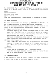
... technology in Fig. APPENDIX 1 Construction of MX-80 Type II and MX-80 F/T Type II The EPSON MX-80 Type I I and MX-80 F/T Type II dot matrix printers (hereinafter referred to as "Type II Printer") consist of the stepper motor corresponds to ...the next print line. Then, the CPU seeks the shortest travel time to one another. 1.1. Printer mechanism The printer mechanism has been developed by the stepper motor, like the head carriage. Al-l, and the driver...
... technology in Fig. APPENDIX 1 Construction of MX-80 Type II and MX-80 F/T Type II The EPSON MX-80 Type I I and MX-80 F/T Type II dot matrix printers (hereinafter referred to as "Type II Printer") consist of the stepper motor corresponds to ...the next print line. Then, the CPU seeks the shortest travel time to one another. 1.1. Printer mechanism The printer mechanism has been developed by the stepper motor, like the head carriage. Al-l, and the driver...

Operation Manual
Page 91
1.3. Printer initialization Printer initialization is interrupted and reapplied (i.e., by turning the Power Switch off and on). (2) Initialization may be driven by activating the INIT signal to energize the ... the primary AC power source is accomplished in either of the print head and two stepper motors. 1.4. This line should be initiated remotely by a TTL driver or its equivalent. Power circuit The power circuit generates 5V DC for the logic circuit, and 24V DC to the parallel interface connector.
1.3. Printer initialization Printer initialization is interrupted and reapplied (i.e., by turning the Power Switch off and on). (2) Initialization may be driven by activating the INIT signal to energize the ... the primary AC power source is accomplished in either of the print head and two stepper motors. 1.4. This line should be initiated remotely by a TTL driver or its equivalent. Power circuit The power circuit generates 5V DC for the logic circuit, and 24V DC to the parallel interface connector.


