Technical Brief (Impact Printers)
Page 4
...network connection AppleTalk connection Compatibility PC/Macintosh PC/Macintosh PC PC PC/Macintosh Macintosh When an optional interface is added, EPSON impact printers automatic interface switching feature will automatically advance the paper to the tear-off , paper parking, and microfeed adjustments. ...drivers guarantees ease of use right out of built-in fonts: LL Bitmap fonts-available on all built-in fonts in fonts that allow you save paper and trouble, and precisely line up printing on most EPSON impact printers. DOS applications will overide all EPSON impact printers...
...network connection AppleTalk connection Compatibility PC/Macintosh PC/Macintosh PC PC PC/Macintosh Macintosh When an optional interface is added, EPSON impact printers automatic interface switching feature will automatically advance the paper to the tear-off , paper parking, and microfeed adjustments. ...drivers guarantees ease of use right out of built-in fonts: LL Bitmap fonts-available on all built-in fonts in fonts that allow you save paper and trouble, and precisely line up printing on most EPSON impact printers. DOS applications will overide all EPSON impact printers...

Product Information Guide
Page 6
...send it is not listed in the software package, any more data for the next print job. When it any Epson 24-pin driver will be compatible. (Preferably, choose the LQ-800/1000.) DIP Switch Settings The default settings will avoid unexpected results. When your system must be checked before ... back on your software you asks you to set to lock in the paper, wait for tractor paper. LQ - 850/950/1050 DOT - The paper can be adjusted for using the printer. MATRIX PRINTER Installation/Support Tips Short Tear Off To activate the short tear-off line and press the FF button. To...
...send it is not listed in the software package, any more data for the next print job. When it any Epson 24-pin driver will be compatible. (Preferably, choose the LQ-800/1000.) DIP Switch Settings The default settings will avoid unexpected results. When your system must be checked before ... back on your software you asks you to set to lock in the paper, wait for tractor paper. LQ - 850/950/1050 DOT - The paper can be adjusted for using the printer. MATRIX PRINTER Installation/Support Tips Short Tear Off To activate the short tear-off line and press the FF button. To...
Product Support Bulletin(s)
Page 15
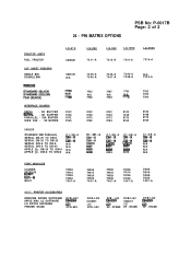
PRINTER ACCESSORIES WINDOWS DRIVER SOFTWARE APPLE MAC LQ SOFTWARE LQ PATCH SOFWARE PRINTER STAND DCB-LQ2 El= CPD-552 DCB-LQ2 C842001 LQ1 CPD-552 DCB - STAND DCB-LQ2 i?iF1 KP - LQ2 ZYO' KP - N/A N/A N/A N/A FONT MODULES COURIER...-A MISC. TRACTOR UNITS PULL TRACTOR CUT SHEET FEEDERS SINGLE BIN DOUBLE BIN 24 - STAND DCB-LQ2 C842001 LQ1 KP - PIN MATRIX OPTIONS PSB No: P-0017B Page: 2 of 2 LQ-510 C800061 LQ-850 7311-A LQ-950 LQ-1050 LQ-2550 7313-A 7312-A 7314-A C806121 N/A 7339-A 7346-A 7345-A 7347-A 7340-A 7348-A N/A 7343-A INTERFACE BOARDS SERIAL - 0K BUFFER - 8K...
PRINTER ACCESSORIES WINDOWS DRIVER SOFTWARE APPLE MAC LQ SOFTWARE LQ PATCH SOFWARE PRINTER STAND DCB-LQ2 El= CPD-552 DCB-LQ2 C842001 LQ1 CPD-552 DCB - STAND DCB-LQ2 i?iF1 KP - LQ2 ZYO' KP - N/A N/A N/A N/A FONT MODULES COURIER...-A MISC. TRACTOR UNITS PULL TRACTOR CUT SHEET FEEDERS SINGLE BIN DOUBLE BIN 24 - STAND DCB-LQ2 C842001 LQ1 KP - PIN MATRIX OPTIONS PSB No: P-0017B Page: 2 of 2 LQ-510 C800061 LQ-850 7311-A LQ-950 LQ-1050 LQ-2550 7313-A 7312-A 7314-A C806121 N/A 7339-A 7346-A 7345-A 7347-A 7340-A 7348-A N/A 7343-A INTERFACE BOARDS SERIAL - 0K BUFFER - 8K...
Technical Manual
Page 10
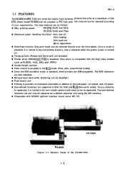
... and FX-1 050 are serial dot matrix 9-pin terminal printers that print at a maximum of the FX-850/1050 1-1 q Two NLQ fonts (Roman and Saris-serif) are also standard. The user-defined character set ) using the DIP switches. q User-defined characters are IBM-compatible. q Printer driver EPSON ESC/P-83 is standard. (This driver is turned on envelopes and...
... and FX-1 050 are serial dot matrix 9-pin terminal printers that print at a maximum of the FX-850/1050 1-1 q Two NLQ fonts (Roman and Saris-serif) are also standard. The user-defined character set ) using the DIP switches. q User-defined characters are IBM-compatible. q Printer driver EPSON ESC/P-83 is standard. (This driver is turned on envelopes and...

Technical Manual
Page 36
... sensors, and printhead are also included on the PEGX board are: Universal IC q STK6722HZ (IC2A Carriage Motor Driver q NJM2355 (lCIA Switching Regulator IC Gate Array q E05A15HA (IC3A Paper Feed and Carriage Motors controller, and Printhead driver q E05A16GA (IC7A Host computer interface Memory IC q EP-ROM (IC4A Program ROM, 256 K-bit q S-...Figure 1-14. PEGX Board DIP SW2 DIP SW1 GA(E05A16GA) 1-27 Since the complicated logic circuit section is the main board, and interfaces the printer to the host computer, controls the printer mechanism and control panel, and supplies DC voltage.
... sensors, and printhead are also included on the PEGX board are: Universal IC q STK6722HZ (IC2A Carriage Motor Driver q NJM2355 (lCIA Switching Regulator IC Gate Array q E05A15HA (IC3A Paper Feed and Carriage Motors controller, and Printhead driver q E05A16GA (IC7A Host computer interface Memory IC q EP-ROM (IC4A Program ROM, 256 K-bit q S-...Figure 1-14. PEGX Board DIP SW2 DIP SW1 GA(E05A16GA) 1-27 Since the complicated logic circuit section is the main board, and interfaces the printer to the host computer, controls the printer mechanism and control panel, and supplies DC voltage.
Technical Manual
Page 110
... -8 4.2.3 Push Tractor Unit Removal 4. -8 4.2.4 Circuit Board Removal 4-9 4.2.4.1 PEGX Board Removal 4-9 4.2.4.2 PEBFIL-11 Board Removal 4-11 4.2.5 Printer Mechanism Disassembly 4-12 4.2.5.1 Printer Mechanism Removal 4-13 4.2.5.2 Printhead Removal 4-14 4.2.5.3 FPC (Flexible Printed Cable) Removal ......... 4-15 4.2.5.4 Carriage Motor Removal 4-16 4.2.5.5 Timing Belt...23 4.2.5.11 Paper Release Lever Removal 4-24 4.2.5.12 Main and Base Frame Removal 4-25 4.2.5.13 Ribbon Driver Unit Removal 4-28 4.2.5.14 Carriage Removal 4-29 4.2.5.15 Paper Guide Plate Removal 4-31 4.2.5.16 Paper Feed...
... -8 4.2.3 Push Tractor Unit Removal 4. -8 4.2.4 Circuit Board Removal 4-9 4.2.4.1 PEGX Board Removal 4-9 4.2.4.2 PEBFIL-11 Board Removal 4-11 4.2.5 Printer Mechanism Disassembly 4-12 4.2.5.1 Printer Mechanism Removal 4-13 4.2.5.2 Printhead Removal 4-14 4.2.5.3 FPC (Flexible Printed Cable) Removal ......... 4-15 4.2.5.4 Carriage Motor Removal 4-16 4.2.5.5 Timing Belt...23 4.2.5.11 Paper Release Lever Removal 4-24 4.2.5.12 Main and Base Frame Removal 4-25 4.2.5.13 Ribbon Driver Unit Removal 4-28 4.2.5.14 Carriage Removal 4-29 4.2.5.15 Paper Guide Plate Removal 4-31 4.2.5.16 Paper Feed...
Technical Manual
Page 112
Ribbon Driver Unit Removal 4-28 Figure 4-4o. LS and Parallel Adjustment Bush Removal 4-30 Figure 4-43. Paper Feed Roller Unit Removal 4-32 Figure 4-46. Paper Holding Roller Lever R Removal 4-33 Figure 4-49. Paper Tension Roller Assembly Removal 4-36 Figure 4-53. Printer Mechanism Separation 4-26 Figure 4-37. Paper Holding Roller Lever L Removal 4-34 Figure...
Ribbon Driver Unit Removal 4-28 Figure 4-4o. LS and Parallel Adjustment Bush Removal 4-30 Figure 4-43. Paper Feed Roller Unit Removal 4-32 Figure 4-46. Paper Holding Roller Lever R Removal 4-33 Figure 4-49. Paper Tension Roller Assembly Removal 4-36 Figure 4-53. Printer Mechanism Separation 4-26 Figure 4-37. Paper Holding Roller Lever L Removal 4-34 Figure...
Technical Manual
Page 140
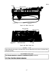
REV.-A \~ Carriage Timing Belt Figure 4-37. Base Frame Unit ASSEMBLY POINT When fitting the main frame to reassemble the printer mechanism: 4.3.2 Paper Feed Motor Backlash Adjustment 4-27 Main Frame Unit Paper Feed Roller A..., PaDer Guide Plate Ribbo~ Driver Home Position Senser FPC Figure 4-38. TADJUSTMENTSREQU'RED The following adjustment is required to the base frame, hook the eight tabs into the holes in the base frame, and pull it forward.
REV.-A \~ Carriage Timing Belt Figure 4-37. Base Frame Unit ASSEMBLY POINT When fitting the main frame to reassemble the printer mechanism: 4.3.2 Paper Feed Motor Backlash Adjustment 4-27 Main Frame Unit Paper Feed Roller A..., PaDer Guide Plate Ribbo~ Driver Home Position Senser FPC Figure 4-38. TADJUSTMENTSREQU'RED The following adjustment is required to the base frame, hook the eight tabs into the holes in the base frame, and pull it forward.
Technical Manual
Page 141
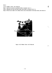
Ribbon Driver Unit Removal .c*- ', 4-28 Tab Tab Figure 4-39. REV.-A 4.2.5.13 Ribbon Driver Unit Removal g$..!'.:, Step 1: Remove the printer mechanism (Refer to Section 4.2.5.1 2.). Step 2: Separate the main and base frame units (Refer to Section 4.2.5. 1.). Step 3: Press the six tabs for the ribbon driver unit at the bottom of the base frame, and remove it.
Ribbon Driver Unit Removal .c*- ', 4-28 Tab Tab Figure 4-39. REV.-A 4.2.5.13 Ribbon Driver Unit Removal g$..!'.:, Step 1: Remove the printer mechanism (Refer to Section 4.2.5.1 2.). Step 2: Separate the main and base frame units (Refer to Section 4.2.5. 1.). Step 3: Press the six tabs for the ribbon driver unit at the bottom of the base frame, and remove it.
Technical Manual
Page 150
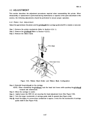
... Turn the larger countersink of carriage guide shaft B (See Figure 4-55). 4-37 Step 8: Insert the blade of a screw driver (a diameter is rotated or removed. Ribbon Mask Holder and Ribbon Mask Configuration Step 4: Reinstall the printhead on the carriage. Step 6:...5: Move the carriage to Section 4.2.5.2.). When disassembly or replacement is performed during maintenance or repaires of the parts described in this printer. Step 1: Remove the printer mechanism (Refer to Section 4.2.5. l.). Figure 4-53. NOTE: When reinstalling the printhead, lock the head lock levers while pushing ...
... Turn the larger countersink of carriage guide shaft B (See Figure 4-55). 4-37 Step 8: Insert the blade of a screw driver (a diameter is rotated or removed. Ribbon Mask Holder and Ribbon Mask Configuration Step 4: Reinstall the printhead on the carriage. Step 6:...5: Move the carriage to Section 4.2.5.2.). When disassembly or replacement is performed during maintenance or repaires of the parts described in this printer. Step 1: Remove the printer mechanism (Refer to Section 4.2.5. l.). Figure 4-53. NOTE: When reinstalling the printhead, lock the head lock levers while pushing ...


