Service Manual
Page 4
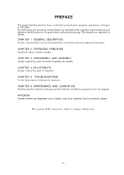
...circuit diagrams, circuit board component layout and exploded diagram. CHAPTER 2. OPERATING PRINCIPLES Describes the theory of the printer. iv - The chapters are intended for adjustment. MAINTENANCE AND LUBRICATION Describes preventive maintenance techniques and lists Lubricants...page. The contents of DFX-5000+. CHAPTER 3. DISASSEMBLY AND ASSEMBLY Includes a step-by -step guide for product disassembly and assembly. PREFACE This manual describes functions, theory of electrical and mechanical operations, maintenance, and repair of this, manual are subject to change ...
...circuit diagrams, circuit board component layout and exploded diagram. CHAPTER 2. OPERATING PRINCIPLES Describes the theory of the printer. iv - The chapters are intended for adjustment. MAINTENANCE AND LUBRICATION Describes preventive maintenance techniques and lists Lubricants...page. The contents of DFX-5000+. CHAPTER 3. DISASSEMBLY AND ASSEMBLY Includes a step-by -step guide for product disassembly and assembly. PREFACE This manual describes functions, theory of electrical and mechanical operations, maintenance, and repair of this, manual are subject to change ...
Service Manual
Page 78
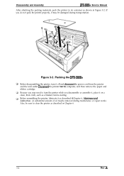
...Assembly DFX-5000+ Service Manual After attaching the packing materials, pack the printer in its container as shown in Chapter 6. 3-2 Rev. Discomect the printer from the printer and the wall outlet. Packing the DFX-5000+ Before disassembling the printer, turn the printer while... you may be sure to turn it on a clean, thick cloth, such as described @Chapter 6, Mainfenunce and Lubrication. (A substantial amount of oil maybe removed during maintenance or repair...
...Assembly DFX-5000+ Service Manual After attaching the packing materials, pack the printer in its container as shown in Chapter 6. 3-2 Rev. Discomect the printer from the printer and the wall outlet. Packing the DFX-5000+ Before disassembling the printer, turn the printer while... you may be sure to turn it on a clean, thick cloth, such as described @Chapter 6, Mainfenunce and Lubrication. (A substantial amount of oil maybe removed during maintenance or repair...
Service Manual
Page 123
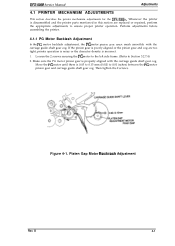
DFX-5000 Service Manual Adjustments 4.1 PRINTER MECHANISM ADJUSTMENTS This section describes the printer mechanism adjustments for the DFX-5000+. If the pinion gear is poorly aligned or the pinion gear and cog are replaced or repaired, perform the appropriate adjustments to Section 3.2.7.4) 2. Loosen the 2 screws securing the PG motor to the left side frame. (Refer to ensure proper printer operation...
DFX-5000 Service Manual Adjustments 4.1 PRINTER MECHANISM ADJUSTMENTS This section describes the printer mechanism adjustments for the DFX-5000+. If the pinion gear is poorly aligned or the pinion gear and cog are replaced or repaired, perform the appropriate adjustments to Section 3.2.7.4) 2. Loosen the 2 screws securing the PG motor to the left side frame. (Refer to ensure proper printer operation...
Service Manual
Page 146
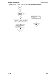
Go back to Section 5.5, Repair of the Printer Mechanism, and check for other problems. ® Perform bidirectional adjustment. eEND Rev. A 5-9 Camiage operation is normal, but the self-testis printed incorrectly (continued). DFX-5000+ Service Manual Troubleshooting 3.
Go back to Section 5.5, Repair of the Printer Mechanism, and check for other problems. ® Perform bidirectional adjustment. eEND Rev. A 5-9 Camiage operation is normal, but the self-testis printed incorrectly (continued). DFX-5000+ Service Manual Troubleshooting 3.
Service Manual
Page 150
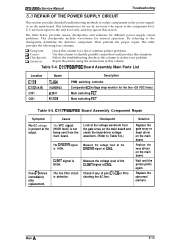
...to identify possible causes that could produce this section. Then perform the proper repair. Repair the printer using the instructions in this column. C117 PSB/PSE Board Assembly Component Repair Symptom No DC voltage is present at CN3. CLIMIT signal is shorting the...printer prints again. Fuse F1 blows immediately after replacement. Checkpoint Look at the voltage waveform from the main board. servicers repair to the unit level only, and may ignore this symptom. Table 5-4. Cause The VPC signal (HIGH level) is defective. DFX-5000+ Service Manual Troubleshooting 5.3 REPAIR...
...to identify possible causes that could produce this section. Then perform the proper repair. Repair the printer using the instructions in this column. C117 PSB/PSE Board Assembly Component Repair Symptom No DC voltage is present at CN3. CLIMIT signal is shorting the...printer prints again. Fuse F1 blows immediately after replacement. Checkpoint Look at the voltage waveform from the main board. servicers repair to the unit level only, and may ignore this symptom. Table 5-4. Cause The VPC signal (HIGH level) is defective. DFX-5000+ Service Manual Troubleshooting 5.3 REPAIR...
Service Manual
Page 152
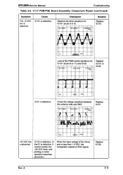
C117 PSB/PSE Board Assembly Component Repair (continued) Rev. A 5-15 DFX-5000+ Service Manual Troubleshooting Table 5-5.
C117 PSB/PSE Board Assembly Component Repair (continued) Rev. A 5-15 DFX-5000+ Service Manual Troubleshooting Table 5-5.
Service Manual
Page 154
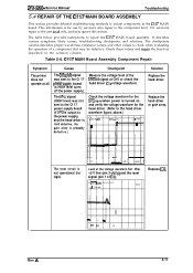
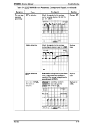
...the voltage waveform for the head driver. (Refer to the head driver waveform figure, above.) ~vl=c mv . CI17 MAIN Board Assembly Component Repair Symptom The printer does not operate at CN1 or check the head driver IC'S voltage waveform. Measure the voltage level of IC9). I 3LY>=J ,66s i ... C117 MAIN board assembly. Check these values and rep, air the board as described in the C117 MAIN board. DFX-5000+ Service Manual Troubleshooting 5.4 REPAIR OF THE C117 MAIN BOARD ASSEMBLY This section provides detailed troubleshooting methods to isolate components in the solution column. - ...
...the voltage waveform for the head driver. (Refer to the head driver waveform figure, above.) ~vl=c mv . CI17 MAIN Board Assembly Component Repair Symptom The printer does not operate at CN1 or check the head driver IC'S voltage waveform. Measure the voltage level of IC9). I 3LY>=J ,66s i ... C117 MAIN board assembly. Check these values and rep, air the board as described in the C117 MAIN board. DFX-5000+ Service Manual Troubleshooting 5.4 REPAIR OF THE C117 MAIN BOARD ASSEMBLY This section provides detailed troubleshooting methods to isolate components in the solution column. - ...
Service Manual
Page 156
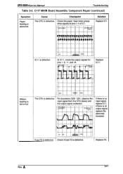
... carriage is ~perating. (The normal voltage level is defective. CI17 MAIN Board Assembly Component Repair (continued) Symptom The carriage operates abnormally. Checkpoint Check the signals for the carriage motor phases at pins 9 anc 11 of IC7. DFX-5000+ Service Manual Troubleshooting Table 5-6. Rev. Check the signals for P-ch. Replace QM1. Replace Q3 or Q6...
... carriage is ~perating. (The normal voltage level is defective. CI17 MAIN Board Assembly Component Repair (continued) Symptom The carriage operates abnormally. Checkpoint Check the signals for the carriage motor phases at pins 9 anc 11 of IC7. DFX-5000+ Service Manual Troubleshooting Table 5-6. Rev. Check the signals for P-ch. Replace QM1. Replace Q3 or Q6...
Service Manual
Page 158
A S-21 C117 MAIN Board Assembly Component Repair (continued) Rev. DFX-5000+ Service Manual Troubleshooting Table 5-6.
A S-21 C117 MAIN Board Assembly Component Repair (continued) Rev. DFX-5000+ Service Manual Troubleshooting Table 5-6.
Service Manual
Page 160
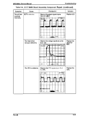
Observe the voltage waveform at pin 15 of IC7. The CPU is printed incorrectly. LIVH j2QV AT. A S-23 C117 MAIN Board Assembly Component Repair (continued) Symptom The self-test is defective. Observe the PTS signal at the drain side. l,92ms SAVE Replace the CPU. Solution Replace IC7. F\ + ++++ 5V 1 Rev. BVI Uv Replace the abnormal FET. The head driver FETs are defective. Checkpoint Observe the output signal at pins 129-137 of the CPU. Cause IC7 is defective. DFX-5000+ Service Manual Troubleshooting Table 5-6.
Observe the voltage waveform at pin 15 of IC7. The CPU is printed incorrectly. LIVH j2QV AT. A S-23 C117 MAIN Board Assembly Component Repair (continued) Symptom The self-test is defective. Observe the PTS signal at the drain side. l,92ms SAVE Replace the CPU. Solution Replace IC7. F\ + ++++ 5V 1 Rev. BVI Uv Replace the abnormal FET. The head driver FETs are defective. Checkpoint Observe the output signal at pins 129-137 of the CPU. Cause IC7 is defective. DFX-5000+ Service Manual Troubleshooting Table 5-6.
Service Manual
Page 162
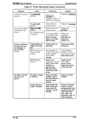
.... Remove the ribbon cartridge, rotate it, and check whether it correctly. Replace the ribbon cartridge. DFX-5000+ Service Manual Troubleshooting Table 5-7. The PF motor is performed, but the printer does not feed paper or does not feed it feeds the ribbon normally. Check if the tip... of the page (darker on one side than the other). Printer Mechanism Repair (continued) Symptom A particular dot does not ...
.... Remove the ribbon cartridge, rotate it, and check whether it correctly. Replace the ribbon cartridge. DFX-5000+ Service Manual Troubleshooting Table 5-7. The PF motor is performed, but the printer does not feed paper or does not feed it feeds the ribbon normally. Check if the tip... of the page (darker on one side than the other). Printer Mechanism Repair (continued) Symptom A particular dot does not ...
Service Manual
Page 164
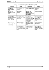
PerForm the tractor wire spring tension adjustment, as described in Section 4.1.3. Printer Mechanism Repair (continued) Symptom Printing occurs outside the paper width. The tractor select (front or rear) function is disconnected from the tractor select cam. Checkpoint Solution Check ... 'w The plunger is incorrect. Check the coil resistance of the tractor wire spring is defective. Visually check the tractor select gear holder. Replace the plunger. DFX-5000+ Service Manual Troubleshooting Table 5-7.
PerForm the tractor wire spring tension adjustment, as described in Section 4.1.3. Printer Mechanism Repair (continued) Symptom Printing occurs outside the paper width. The tractor select (front or rear) function is disconnected from the tractor select cam. Checkpoint Solution Check ... 'w The plunger is incorrect. Check the coil resistance of the tractor wire spring is defective. Visually check the tractor select gear holder. Replace the plunger. DFX-5000+ Service Manual Troubleshooting Table 5-7.


