Technical Brief (Impact Printers)
Page 1
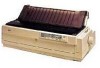
...four pin printers all have 3 numbers in their names EPSON Sales Training EPSON is a 9- L LL L Nine-pin impact printers - An impact printer has several advantages over any other type of multi-part forms that can all begin with tireless printheads and superior quality ribbons. EPSON impact printers are ... printing and the number of printer: Low cost - only impact printers can handle multi-part forms and multiple paper paths that the printer are either 9- both in their reliability with LQ FX-980-Nine-pin narrow carriage Wide carriage printers have 4 number in purchase ...
...four pin printers all have 3 numbers in their names EPSON Sales Training EPSON is a 9- L LL L Nine-pin impact printers - An impact printer has several advantages over any other type of multi-part forms that can all begin with tireless printheads and superior quality ribbons. EPSON impact printers are ... printing and the number of printer: Low cost - only impact printers can handle multi-part forms and multiple paper paths that the printer are either 9- both in their reliability with LQ FX-980-Nine-pin narrow carriage Wide carriage printers have 4 number in purchase ...

User Manual
Page 1
...EPSON® 24-Pin Dot Matrix Printer LQ-2070 All rights reserved. Seiko Epson Corporation and its affiliates shall be reproduced, stored in a retrieval system, or transmitted in any form or by any liability assumed for damages, losses, costs, or expenses incurred by purchaser or third parties as Original EPSON Products or EPSON Approved Products by Seiko Epson... may be liable against any damages or problems arising from the use of Epson America, Inc. No part of Seiko Epson Corporation. No patent liability is any means, electronic, mechanical, photocopying, recording...
...EPSON® 24-Pin Dot Matrix Printer LQ-2070 All rights reserved. Seiko Epson Corporation and its affiliates shall be reproduced, stored in a retrieval system, or transmitted in any form or by any liability assumed for damages, losses, costs, or expenses incurred by purchaser or third parties as Original EPSON Products or EPSON Approved Products by Seiko Epson... may be liable against any damages or problems arising from the use of Epson America, Inc. No part of Seiko Epson Corporation. No patent liability is any means, electronic, mechanical, photocopying, recording...
User Manual
Page 94
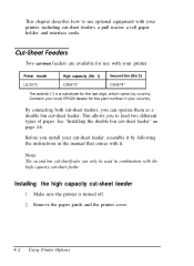
... the instructions in combination with your local EPSON dealer for use optional equipment with it. Remove the paper guide and the printer cover. 4-2 Using Printer Options Cut-Sheet Feeders Two cut -sheet feeder. Printer model High capacity (Bin 1) Second bin (Bin 2) LQ-2070 C80673* C80674* The asterisk (*) is ...By connecting both cut-sheet feeders, you to use with the high capacity cut -sheet feeders are available for the part number in your printer, including cut -sheet feeder. This allows you can only be used in the manual that comes with your country....
... the instructions in combination with your local EPSON dealer for use optional equipment with it. Remove the paper guide and the printer cover. 4-2 Using Printer Options Cut-Sheet Feeders Two cut -sheet feeder. Printer model High capacity (Bin 1) Second bin (Bin 2) LQ-2070 C80673* C80674* The asterisk (*) is ...By connecting both cut-sheet feeders, you to use with the high capacity cut -sheet feeders are available for the part number in your printer, including cut -sheet feeder. This allows you can only be used in the manual that comes with your country....
User Manual
Page 109
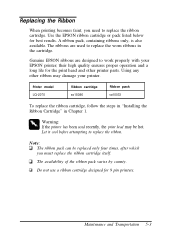
... ribbon cartridge. Printer model LQ-2070 Ribbon cartridge so15086 Ribbon pack so10033 To replace the ribbon cartridge, follow the steps in "Installing the Ribbon Cartridge" in the cartridge. Let it cool before attempting to work properly with your printer. Using any other printer parts. Do not... pack varies by county. Use the EPSON ribbon cartridge or pack listed below for 9 pin printers. A ribbon pack, containing ribbons only, is also available. Genuine EPSON ribbons are used recently, the print head may damage your EPSON printer; their high quality ensures proper operation and...
... ribbon cartridge. Printer model LQ-2070 Ribbon cartridge so15086 Ribbon pack so10033 To replace the ribbon cartridge, follow the steps in "Installing the Ribbon Cartridge" in the cartridge. Let it cool before attempting to work properly with your printer. Using any other printer parts. Do not... pack varies by county. Use the EPSON ribbon cartridge or pack listed below for 9 pin printers. A ribbon pack, containing ribbons only, is also available. Genuine EPSON ribbons are used recently, the print head may damage your EPSON printer; their high quality ensures proper operation and...

Service Manual
Page 54
... 2-6 Rev.A In the push tractor method, the release lever is set to one of the black arrow and thus feeds paper into the printer. When the push tractor method is transmitted to release the pressure between the paper guide roller and the platen. Figure 2-6 illustrates push tractor ...gear, and tractor reduction gear. Operation Principles LQ-2070 Servcie Manual 2. When the PF motor pinion gear turns in the direction of the black arrow, the tractor gear rotates in the front part of the black arrow, and thus feeds paper into the printer. When the push tractor method is transmitted...
... 2-6 Rev.A In the push tractor method, the release lever is set to one of the black arrow and thus feeds paper into the printer. When the push tractor method is transmitted to release the pressure between the paper guide roller and the platen. Figure 2-6 illustrates push tractor ...gear, and tractor reduction gear. Operation Principles LQ-2070 Servcie Manual 2. When the PF motor pinion gear turns in the direction of the black arrow, the tractor gear rotates in the front part of the black arrow, and thus feeds paper into the printer. When the push tractor method is transmitted...

Service Manual
Page 79
...Tool Round-nose pliers Nippers Tweezers Soldering iron E-ring holder #2.5 Phillips screwdriver No. Standard screwdriver Thickness gauge Part No. Table 3-2. Rev.A 3-1 CAUTION To maintain efficient printer operation: • Use only recommended tools for disassembly or assembly. B740400100 B740500100 B741000100 B740200100 B740800400 B743800200 ...remains live even after the power switch is required only for disassembling, assembling, or adjusting the printer. LQ-2070 Service Manual Disassembly and Assembly 3.1 OVERVIEW This section describes various points to the AC power socket....
...Tool Round-nose pliers Nippers Tweezers Soldering iron E-ring holder #2.5 Phillips screwdriver No. Standard screwdriver Thickness gauge Part No. Table 3-2. Rev.A 3-1 CAUTION To maintain efficient printer operation: • Use only recommended tools for disassembly or assembly. B740400100 B740500100 B741000100 B740200100 B740800400 B743800200 ...remains live even after the power switch is required only for disassembling, assembling, or adjusting the printer. LQ-2070 Service Manual Disassembly and Assembly 3.1 OVERVIEW This section describes various points to the AC power socket....
Service Manual
Page 80
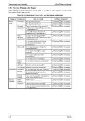
...the bidirectional print position adjusted correctly? Disassembly and Assembly LQ-2070 Service Manual 3.1.3 Service Checks After Repair Before returning the printer after service, use the check list in Table 3-3, which provides a record to Check Printer units Printhead Are any wires worn out? Inspection Check ... of distortion? Was the self-test successful? Is Check Required? Table 3-3. Is the ribbon mask free of all relevant parts been included in the shipment? System upgrade ROM version ROM version ________. Are any wires broken? advance Movement noisy Mechanism ...
...the bidirectional print position adjusted correctly? Disassembly and Assembly LQ-2070 Service Manual 3.1.3 Service Checks After Repair Before returning the printer after service, use the check list in Table 3-3, which provides a record to Check Printer units Printhead Are any wires worn out? Inspection Check ... of distortion? Was the self-test successful? Is Check Required? Table 3-3. Is the ribbon mask free of all relevant parts been included in the shipment? System upgrade ROM version ROM version ________. Are any wires broken? advance Movement noisy Mechanism ...

Service Manual
Page 81
Table 3-4. LQ-2070 Service Manual Disassembly and Assembly 3.1.4 Specifications for Screws Table 3-4 lists the abbreviations used in the following sections for small parts, such as screws and washers. Screw Types and Abbreviations Abbreviation CPS CBB CBS CBN CBC CBA CB(O) Part Name Cross-recessed pan head S-tight screw Cross-recessed bind head B-tight screw Cross...
Table 3-4. LQ-2070 Service Manual Disassembly and Assembly 3.1.4 Specifications for Screws Table 3-4 lists the abbreviations used in the following sections for small parts, such as screws and washers. Screw Types and Abbreviations Abbreviation CPS CBB CBS CBN CBC CBA CB(O) Part Name Cross-recessed pan head S-tight screw Cross-recessed bind head B-tight screw Cross...

Service Manual
Page 82
... operation. Also disconnect the interface cable. • Whenever the printer is replaced). PG adjustment required. Disassembly and Assembly LQ-2070 Service Manual 3.2. PRINTER DISASSEMBLY AND ASSEMBLY This section describes procedures for Disassembling the Printer 3-4 Rev.A Note: Exploded diagrams in these notes. TPE level reset required (when part is simply the reverse of the required adjustments, refer...
... operation. Also disconnect the interface cable. • Whenever the printer is replaced). PG adjustment required. Disassembly and Assembly LQ-2070 Service Manual 3.2. PRINTER DISASSEMBLY AND ASSEMBLY This section describes procedures for Disassembling the Printer 3-4 Rev.A Note: Exploded diagrams in these notes. TPE level reset required (when part is simply the reverse of the required adjustments, refer...

Service Manual
Page 83
Rev.A 3-5 When remounting them, be sure to release the hooks at both sides. LQ-2070 Service Manual Disassembly and Assembly 3.2.1. Before Starting Disassembly Procedures 1. Remove the following parts: È Front edge guide assembly ‘ Front cover Ç Rear edge guide assembly • Printer cover . Front/rear tractor assembly ° Ribbon cartridge Refer to the...
Rev.A 3-5 When remounting them, be sure to release the hooks at both sides. LQ-2070 Service Manual Disassembly and Assembly 3.2.1. Before Starting Disassembly Procedures 1. Remove the following parts: È Front edge guide assembly ‘ Front cover Ç Rear edge guide assembly • Printer cover . Front/rear tractor assembly ° Ribbon cartridge Refer to the...
Service Manual
Page 92
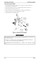
Disassembly and Assembly LQ-2070 Service Manual 3.2.9.1 Removing the PF Motor 1. Remove the panel board (see Section 3.2.2) and upper housing assembly (see Section 3.2.9). 4. Remove the printer mechanism (see Section 3.2.7). 3. Disconnect connector CN10 from the right sub frame. The CBS screw (3 × 6, F/Zn ) is ...Section 3.2.1). 2. Remove the PF motor from the C186 MAIN board assembly. 6. The CB screw (3 × 8, F/Zn) is used to secure the upper part of the PF motor. The tightening torque for the CB and CBS screws (3 × 8, F/Zn) = 0.78 ~ 0.98 Nm (8 ~ 10 Kg ...
Disassembly and Assembly LQ-2070 Service Manual 3.2.9.1 Removing the PF Motor 1. Remove the panel board (see Section 3.2.2) and upper housing assembly (see Section 3.2.9). 4. Remove the printer mechanism (see Section 3.2.7). 3. Disconnect connector CN10 from the right sub frame. The CBS screw (3 × 6, F/Zn ) is ...Section 3.2.1). 2. Remove the PF motor from the C186 MAIN board assembly. 6. The CB screw (3 × 8, F/Zn) is used to secure the upper part of the PF motor. The tightening torque for the CB and CBS screws (3 × 8, F/Zn) = 0.78 ~ 0.98 Nm (8 ~ 10 Kg ...

Service Manual
Page 95
Refer to Chapter 4. Remove the following figures. Mount the 11 parts above on the right frame assembly, as shown in the following 11 parts from the MAIN board assembly. 3. Compression Spring (200g) Plain Wahser (8.2x0.5x1.5S/Na) Spur Gear (21 mm) Spur Gear (34.5 mm)... Gear (8mm/30mm) Intermittent Gear Spur Gear (27mm) Spur Gear (34.5mm) Spur Gear (34mm) Figure 3-21 Engaging Gears 1 Rev.A 3-17 LQ-2070 Service Manual Disassembly and Assembly 2. Remove the right sub frame from the right frame assembly by disconnecting CN16 from the right frame assembly. 2 compression springs...
Refer to Chapter 4. Remove the following figures. Mount the 11 parts above on the right frame assembly, as shown in the following 11 parts from the MAIN board assembly. 3. Compression Spring (200g) Plain Wahser (8.2x0.5x1.5S/Na) Spur Gear (21 mm) Spur Gear (34.5 mm)... Gear (8mm/30mm) Intermittent Gear Spur Gear (27mm) Spur Gear (34.5mm) Spur Gear (34mm) Figure 3-21 Engaging Gears 1 Rev.A 3-17 LQ-2070 Service Manual Disassembly and Assembly 2. Remove the right sub frame from the right frame assembly by disconnecting CN16 from the right frame assembly. 2 compression springs...

Service Manual
Page 114
... Item \ Adjustment Platen Bi-d Print Factory TPE Level Gap Alignment Settings Reset Printer Mechanism Replacement -- ( f1) r ( f 2) -- envelopes. r -- -- CR Assembly Replacement or Removal r r -- -- ( f 1) : -- Note When any part is removed or replaced. Right Frame Assembly Replacement or Removal r r -- -- RD Assembly Replacement or Removal r r -- -- LQ-2070 Service Manual Adjustment 4.1 ADJUSTMENT OVERVIEW 4.1.1 Required Adjustments This section describes what...
... Item \ Adjustment Platen Bi-d Print Factory TPE Level Gap Alignment Settings Reset Printer Mechanism Replacement -- ( f1) r ( f 2) -- envelopes. r -- -- CR Assembly Replacement or Removal r r -- -- ( f 1) : -- Note When any part is removed or replaced. Right Frame Assembly Replacement or Removal r r -- -- RD Assembly Replacement or Removal r r -- -- LQ-2070 Service Manual Adjustment 4.1 ADJUSTMENT OVERVIEW 4.1.1 Required Adjustments This section describes what...
Service Manual
Page 123
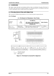
... Reading Refer to the Place one lead on abnormal symptoms. The checkpoint tables let you identify the faulty part or unit by checking the values or ranges listed for each component. 5.2 TROUBLESHOOTING INFORMATION This section gives ... R R F 3 1 1 2 19 7 C 3 C 6 C 2 2 2 1 5 1 8 23 1 0 1 4 6 F 5 1 13 9 21 17 C5 C4 C1 24 20 12 8 16 T T 4 R COM. Flowcharts let you troubleshoot the printer. Printhead Coil Resistance Test Points Common Pin No. LQ-2070 Service Manual Troubleshooting 5.1 OVERVIEW This chapter contains flowcharts and checkpoint tables to the following figure.
... Reading Refer to the Place one lead on abnormal symptoms. The checkpoint tables let you identify the faulty part or unit by checking the values or ranges listed for each component. 5.2 TROUBLESHOOTING INFORMATION This section gives ... R R F 3 1 1 2 19 7 C 3 C 6 C 2 2 2 1 5 1 8 23 1 0 1 4 6 F 5 1 13 9 21 17 C5 C4 C1 24 20 12 8 16 T T 4 R COM. Flowcharts let you troubleshoot the printer. Printhead Coil Resistance Test Points Common Pin No. LQ-2070 Service Manual Troubleshooting 5.1 OVERVIEW This chapter contains flowcharts and checkpoint tables to the following figure.
Service Manual
Page 131
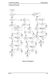
...cable correctly. YES NO Replace the FFC. Check the FFC using a multimeter. Are any bad parts. FFC. YES NO Is the YES probelm corrected? Are the correct printer drivers installed ? NO YES Is the NO FFC connected correctly? Is it OK? missing ?...YES probelm corrected? Replace the C186 MAIN abord EENNDD Is the bottom of printhead wires check OK? LQ-2070 Service Manual 4. YES Replace the printhead.. Reset the printer. YES NO Is the YES problem corrected ? EEENNNDDD NO Is the YES problem corrected ? EENNDD ...
...cable correctly. YES NO Replace the FFC. Check the FFC using a multimeter. Are any bad parts. FFC. YES NO Is the YES probelm corrected? Are the correct printer drivers installed ? NO YES Is the NO FFC connected correctly? Is it OK? missing ?...YES probelm corrected? Replace the C186 MAIN abord EENNDD Is the bottom of printhead wires check OK? LQ-2070 Service Manual 4. YES Replace the printhead.. Reset the printer. YES NO Is the YES problem corrected ? EEENNNDDD NO Is the YES problem corrected ? EENNDD ...

Service Manual
Page 143
LQ-2070 Service Manual Maintenance 6.1 PREVENTIVE MAINTENANCE Preventive maintenance includes regular ...G-26 G-26 G-26 G-26 Note: Lubrication must be sure the surface to the following pages. CAUTION Disconnect the printer from the bottom. About 1/2 the size of a grain of rice About the whole the size of a grain...Name G-26 O-2 Quantity 40 gm 40 cc Availability EPSON EPSON Part No. Before returning the printer to the figure on the plastic components of the printer. 6.2 APPLYING LUBRICATION EPSON recommends the printer be lubricated at the points illustrated to be lubricated is...
LQ-2070 Service Manual Maintenance 6.1 PREVENTIVE MAINTENANCE Preventive maintenance includes regular ...G-26 G-26 G-26 G-26 Note: Lubrication must be sure the surface to the following pages. CAUTION Disconnect the printer from the bottom. About 1/2 the size of a grain of rice About the whole the size of a grain...Name G-26 O-2 Quantity 40 gm 40 cc Availability EPSON EPSON Part No. Before returning the printer to the figure on the plastic components of the printer. 6.2 APPLYING LUBRICATION EPSON recommends the printer be lubricated at the points illustrated to be lubricated is...

Service Manual
Page 147
PARTS LIST A-1 A-2 A-5 A-11 A-17 A-20 A-26 List of Contents A.1. Cable Connections A-5 Figure A-2. C186 MAIN Board Assembly Component Layout A-17 Figure A-6. Connector Summary A-6 Table ... Pin Assignments - CN12 A-8 Table A-12. Connector Pin Assignments - C166 PSE Board Assembly Component Layout A-19 Figure A-8. CSF Bin 1 Exploded Diagrams (1 A-23 Figure A-12. LQ-2070 Exploded Diagrams (3 A-22 Figure A-11. CN5 A-7 Table A-5. CN9 A-8 Table A-9. Connector Pin Assignments - EXPANDED PRODUCTION COMMANDS A.2. C186 MAIN Board Assembly Circuit Diagram A-11 Figure ...
PARTS LIST A-1 A-2 A-5 A-11 A-17 A-20 A-26 List of Contents A.1. Cable Connections A-5 Figure A-2. C186 MAIN Board Assembly Component Layout A-17 Figure A-6. Connector Summary A-6 Table ... Pin Assignments - CN12 A-8 Table A-12. Connector Pin Assignments - C166 PSE Board Assembly Component Layout A-19 Figure A-8. CSF Bin 1 Exploded Diagrams (1 A-23 Figure A-12. LQ-2070 Exploded Diagrams (3 A-22 Figure A-11. CN5 A-7 Table A-5. CN9 A-8 Table A-9. Connector Pin Assignments - EXPANDED PRODUCTION COMMANDS A.2. C186 MAIN Board Assembly Circuit Diagram A-11 Figure ...

Service Manual
Page 158
X: Not available. LQ - 2070 (24pins) LQ -2170 (24pins) C186 C166 C165 C165 X 1 Located at both sides O 1 2 on left side FX - 2170 (9pins) C165 C165 O 2 2 on left side EM-248 (AM0083) EM-247 EM-241 EM-242 EM-247 EM-241 EM-243 EM-249 A-10 Rev.A Appendix LQ-2070 Service Manual Table A-16 Parts Comparison Between LQ2070, LQ 2170 and FX 2170 Main Board PSB/PSE Board Cover Open Sensor PG sensors Release Lever Sensors CR Motor PF Motor O: Available.
X: Not available. LQ - 2070 (24pins) LQ -2170 (24pins) C186 C166 C165 C165 X 1 Located at both sides O 1 2 on left side FX - 2170 (9pins) C165 C165 O 2 2 on left side EM-248 (AM0083) EM-247 EM-241 EM-242 EM-247 EM-241 EM-243 EM-249 A-10 Rev.A Appendix LQ-2070 Service Manual Table A-16 Parts Comparison Between LQ2070, LQ 2170 and FX 2170 Main Board PSB/PSE Board Cover Open Sensor PG sensors Release Lever Sensors CR Motor PF Motor O: Available.
Service Manual
Page 159
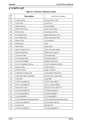
Appendix LQ-2070 Service Manual A.7.PARTS LIST Table A-17 Part No. Screw(M4x14) 122 C.B.C-Lamitite(M3x8) 123 Rivet B-Tite Screw 123 C.B.B. B.Screw(M3x8) 125 C.B.Screw(M2X7) 126 Printer Mechanism Mounting Screw 127 C.B.B. Screw (M4X12) Hexagon Nut C.B.B.Screw(M4X12) A-26 Rev.A Screw (M3x8) C.B.C. Lamititie (M3x8) Rivet ...) 124 C.B. No. Screw(M4X12) 128 Hexagon Nut 129 C.B.B. Screw(M4X12) Parts Price List Name Housing Assy,.Lower Cover,Front Housing,Upper Cover, Printer,Rear Cover,Assy.,Printer Edge Guide Assy.,Front Edge Guide Assy.,Rear Cover,Bottom Knob Shield Plate Cover,...
Appendix LQ-2070 Service Manual A.7.PARTS LIST Table A-17 Part No. Screw(M4x14) 122 C.B.C-Lamitite(M3x8) 123 Rivet B-Tite Screw 123 C.B.B. B.Screw(M3x8) 125 C.B.Screw(M2X7) 126 Printer Mechanism Mounting Screw 127 C.B.B. Screw (M4X12) Hexagon Nut C.B.B.Screw(M4X12) A-26 Rev.A Screw (M3x8) C.B.C. Lamititie (M3x8) Rivet ...) 124 C.B. No. Screw(M4X12) 128 Hexagon Nut 129 C.B.B. Screw(M4X12) Parts Price List Name Housing Assy,.Lower Cover,Front Housing,Upper Cover, Printer,Rear Cover,Assy.,Printer Edge Guide Assy.,Front Edge Guide Assy.,Rear Cover,Bottom Knob Shield Plate Cover,...
Service Manual
Page 160
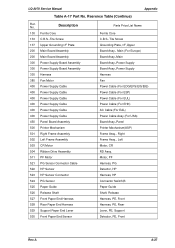
... Paper Guide Shaft, Release Harness, PE, Front Harness, PE, Rear Lever, PE, Support Detector, PE, Front Rev.A A-27 No. LQ-2070 Service Manual Appendix Table A-17 Part No. Reerence Table (Continue) Ref. Description 130 Ferrite Core 133 C.B.S.-Tite Screw 137 Upper Grounding I/F Plate 200 Main Board Assembly 200 Main... Cable 400 Power Supply Cable 400 Power Supply Cable 400 Power Supply Cable 400 Power Supply Cable 450 Panel Board Assembly 500 Printer Mechanism 501 Right Frame Assembly 502 Left Frame Assembly 503 CR Motor 504 Ribbon Drive Assembly 511 PF Motor 521 PG Sensor ...
... Paper Guide Shaft, Release Harness, PE, Front Harness, PE, Rear Lever, PE, Support Detector, PE, Front Rev.A A-27 No. LQ-2070 Service Manual Appendix Table A-17 Part No. Reerence Table (Continue) Ref. Description 130 Ferrite Core 133 C.B.S.-Tite Screw 137 Upper Grounding I/F Plate 200 Main Board Assembly 200 Main... Cable 400 Power Supply Cable 400 Power Supply Cable 400 Power Supply Cable 400 Power Supply Cable 450 Panel Board Assembly 500 Printer Mechanism 501 Right Frame Assembly 502 Left Frame Assembly 503 CR Motor 504 Ribbon Drive Assembly 511 PF Motor 521 PG Sensor ...


