User Manual
Page 32
... the Control Panel group. If you need to install the printer driver. Insert the EPSON driver disk into drive A (or B, depending on your printer's capabilities. Select LQ-2070 ESC/P 2 as two utilities to install the printer driver for instructions. Installing the Printer Driver The EPSON printer driver is installed automatically. 6. Windows will now use the Printers utility in the next section to change the default...
... the Control Panel group. If you need to install the printer driver. Insert the EPSON driver disk into drive A (or B, depending on your printer's capabilities. Select LQ-2070 ESC/P 2 as two utilities to install the printer driver for instructions. Installing the Printer Driver The EPSON printer driver is installed automatically. 6. Windows will now use the Printers utility in the next section to change the default...
User Manual
Page 38
... users Most DOS software programs include drivers for instructions on selecting the printer driver. Setting Up the Printer 1-21 You can use EPSON Remote! If the LQ-2070 is an updated driver available or select the first printer available from your software manufacturer to install the printer driver. Also, DOS programs require you can use EPSON Calibration to make setting changes from...
... users Most DOS software programs include drivers for instructions on selecting the printer driver. Setting Up the Printer 1-21 You can use EPSON Remote! If the LQ-2070 is an updated driver available or select the first printer available from your software manufacturer to install the printer driver. Also, DOS programs require you can use EPSON Calibration to make setting changes from...
Service Manual
Page 45
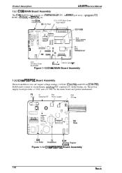
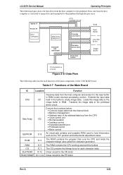
Head Driva TRANSISTOR IC 5 PS RAM ICI 1,14 PF Motor Driver TEA3718SDP 1 1 ~n D .H / \ IC12 CR Motor Driver SLA7024M IC 8 'CN2 for the main board and printer mechanism. Both boards consist of a TMP96C041AF CPU, an E05B13 gate array, a program/CG ROM, a PS-IWM, an EEPROM,... Assembly 1.6.2 C166 PSB/PSE Board Assembly These boardshave two AC input voltage ratings: 120VAC (C166PSB) and230VAC (C166PSE). Product Description LQ-2070 Service Manual 1.6.1 C186 MAIN Board Assembly The C186 MAIN board consists of a transformer, switcking FET, regulator IC, diode bridge, etc. C!!!!!o0 ;
Head Driva TRANSISTOR IC 5 PS RAM ICI 1,14 PF Motor Driver TEA3718SDP 1 1 ~n D .H / \ IC12 CR Motor Driver SLA7024M IC 8 'CN2 for the main board and printer mechanism. Both boards consist of a TMP96C041AF CPU, an E05B13 gate array, a program/CG ROM, a PS-IWM, an EEPROM,... Assembly 1.6.2 C166 PSB/PSE Board Assembly These boardshave two AC input voltage ratings: 120VAC (C166PSB) and230VAC (C166PSE). Product Description LQ-2070 Service Manual 1.6.1 C186 MAIN Board Assembly The C186 MAIN board consists of a transformer, switcking FET, regulator IC, diode bridge, etc. C!!!!!o0 ;
Service Manual
Page 49
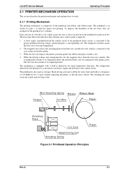
... arranged on the printhead in 2 columns. The dot wire also returns to print a single dot. 1. When the driving voltage stops energizing the coil, the magnetic force from the control circuit to the printhead driver circuit, is converted to the proper printhead driving ...thermistor is converted to an electric signal and fed back to become magnetized. 2. LQ-2070 Service Manual Operating Principles 2.1 PRINTER MECHANISM OPERATION This section describes the printer mechanism and explains how it prints a dot. 4. To improve the durability of the printhead, ink ribbon, and ribbon mask...
... arranged on the printhead in 2 columns. The dot wire also returns to print a single dot. 1. When the driving voltage stops energizing the coil, the magnetic force from the control circuit to the printhead driver circuit, is converted to the proper printhead driving ...thermistor is converted to an electric signal and fed back to become magnetized. 2. LQ-2070 Service Manual Operating Principles 2.1 PRINTER MECHANISM OPERATION This section describes the printer mechanism and explains how it prints a dot. 4. To improve the durability of the printhead, ink ribbon, and ribbon mask...

Service Manual
Page 65
LQ-2070 Service Manual Operating Principles 2.2 POWER SUPPLY OPERATION The printer can be powered by either of the power supply circuitry. These boards are the same as the FX-2170. Power Supply Board Board C166 PSB C166 PSE Input Voltage 103.5 to 132 VAC 198 to drive the printer... to a stable +5 VDC from an external power source, the filter circuit removes the noise. Rev.A 2-17 Control Panel LEDs Printhead Driver Primary Circuit Secondary Circuit +5V Switching Regurator +5V Constant Voltage Control Circuit +5V Over current Protection Circuit +5V DC Full Wave Rectification ...
LQ-2070 Service Manual Operating Principles 2.2 POWER SUPPLY OPERATION The printer can be powered by either of the power supply circuitry. These boards are the same as the FX-2170. Power Supply Board Board C166 PSB C166 PSE Input Voltage 103.5 to 132 VAC 198 to drive the printer... to a stable +5 VDC from an external power source, the filter circuit removes the noise. Rev.A 2-17 Control Panel LEDs Printhead Driver Primary Circuit Secondary Circuit +5V Switching Regurator +5V Constant Voltage Control Circuit +5V Over current Protection Circuit +5V DC Full Wave Rectification ...
Service Manual
Page 71
Transfers the image data to create image data. Extends the input data IC1 held in the buffer to the printhead driver circuit. Loads this image data to hold information such as the TOF position and bidirectional adjustment value. RAM IC 5 The RAM contains the CPU... the CPU and holds the character design (also called the character generator). LQ-2070 Service Manual Operating Principles The following table lists the each character table SLA7024M IC 12 Driver circuit for the CR motor TEA3718SDP IC 11,14 Driver circuit for each function of the main components of the C186 MAIN board....
Transfers the image data to create image data. Extends the input data IC1 held in the buffer to the printhead driver circuit. Loads this image data to hold information such as the TOF position and bidirectional adjustment value. RAM IC 5 The RAM contains the CPU... the CPU and holds the character design (also called the character generator). LQ-2070 Service Manual Operating Principles The following table lists the each character table SLA7024M IC 12 Driver circuit for the CR motor TEA3718SDP IC 11,14 Driver circuit for each function of the main components of the C186 MAIN board....
Service Manual
Page 72
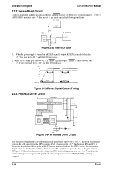
...100 ms passes. 2. When the power supply is made in the CPU operates. RESET is output from port 1 (VOUT) of IC10. Operation Principles LQ-2070 Servcie Manual 2.3.2 System Reset Circuit Control circuits IC1 and IC2 are initialized when a RESET signal (LOW level) is canceled when the +5 V line goes... ms passes. (v) 5 4 3 2 1 Power On 100ms RESET VOUT (RESET) 100ms RESET VCC (+5V line) Figure 2-33 Reset Signal Output Timing 2.3.3 Printhead Driver Circuit Print Head +35V +35V + C9 HT MP Printhead Drive Transistor Q1~Q12, Q13~24 R49 Printhead Drive Signal 69 76~89 91~99 ~ ~ Gate...
...100 ms passes. 2. When the power supply is made in the CPU operates. RESET is output from port 1 (VOUT) of IC10. Operation Principles LQ-2070 Servcie Manual 2.3.2 System Reset Circuit Control circuits IC1 and IC2 are initialized when a RESET signal (LOW level) is canceled when the +5 V line goes... ms passes. (v) 5 4 3 2 1 Power On 100ms RESET VOUT (RESET) 100ms RESET VCC (+5V line) Figure 2-33 Reset Signal Output Timing 2.3.3 Printhead Driver Circuit Print Head +35V +35V + C9 HT MP Printhead Drive Transistor Q1~Q12, Q13~24 R49 Printhead Drive Signal 69 76~89 91~99 ~ ~ Gate...
Service Manual
Page 73
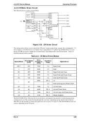
LQ-2070 Service Manual 2.3.4 CR Motor Driver Circuit The CR motor driver circuit is equivalent to change the excitation phase, depending on the CR speed. The current flowing through the coil varies, depending on the speed of ... 3300 1-2 Draft and Power Down 4400 W1-2 LQ 1 92 1-2 Draft and Copy and Power Down 2/3 61 1464 1-2 LQ and Copy 1/2 46 2200 W1-2 LQ and Power Down 1/3 31 1464 W1-2 LQ and Copy and Power Down 1/4 23 1100 W1-2 Raster Graphics The SLA7024M (IC12) CR motor driver circuit detects and regulates the amount of the...
LQ-2070 Service Manual 2.3.4 CR Motor Driver Circuit The CR motor driver circuit is equivalent to change the excitation phase, depending on the CR speed. The current flowing through the coil varies, depending on the speed of ... 3300 1-2 Draft and Power Down 4400 W1-2 LQ 1 92 1-2 Draft and Copy and Power Down 2/3 61 1464 1-2 LQ and Copy 1/2 46 2200 W1-2 LQ and Power Down 1/3 31 1464 W1-2 LQ and Copy and Power Down 1/4 23 1100 W1-2 Raster Graphics The SLA7024M (IC12) CR motor driver circuit detects and regulates the amount of the...
Service Manual
Page 74
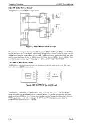
...drive currents are output via ports 32 (PHASEA) and ports 129 (PHASEB) to TEA3718SDP form, and then sends that stores information even if the printer power is controlled on port 20 (INTO), the CPU writes the necessary data to the EEPROM before the +5 V line drops to the each...14 GND1 GND2 GND3 GND4 C66 C73 C67 D4 1 PF A 3 PF-A D5 +35 D6 C67 +35 D7 2 4 PF B PF-B Figure 2-36 PF Motor Driver Circuit The gate array receives phase data from the EEPROM. Operation Principles LQ-2070 Servcie Manual 2.3.5 PF Motor Driver Circuit The figure below shows the EEPROM control circuit.
...drive currents are output via ports 32 (PHASEA) and ports 129 (PHASEB) to TEA3718SDP form, and then sends that stores information even if the printer power is controlled on port 20 (INTO), the CPU writes the necessary data to the EEPROM before the +5 V line drops to the each...14 GND1 GND2 GND3 GND4 C66 C73 C67 D4 1 PF A 3 PF-A D5 +35 D6 C67 +35 D7 2 4 PF B PF-B Figure 2-36 PF Motor Driver Circuit The gate array receives phase data from the EEPROM. Operation Principles LQ-2070 Servcie Manual 2.3.5 PF Motor Driver Circuit The figure below shows the EEPROM control circuit.

Service Manual
Page 75
...been loaded when the photo diode rays are cut off by the sensor plate, which is included in this printer. Pages 2-3 and 2-4 describe the relationship between release and PG sensor operation and actual print operation. Release sensors... front PE sensor are photo diode switches. The HP sensor, rear PE sensor, and PW sensor are momentary switches. LQ-2070 Service Manual Operating Principles 2.3.7 Sensor Circuits The CPU detects conditions of the following sensors: home position (HP) sensor, ... HP Sensor PG Sensor Release Sensor 2 Release Sensor 1 Two types of the head driver signal.
...been loaded when the photo diode rays are cut off by the sensor plate, which is included in this printer. Pages 2-3 and 2-4 describe the relationship between release and PG sensor operation and actual print operation. Release sensors... front PE sensor are photo diode switches. The HP sensor, rear PE sensor, and PW sensor are momentary switches. LQ-2070 Service Manual Operating Principles 2.3.7 Sensor Circuits The CPU detects conditions of the following sensors: home position (HP) sensor, ... HP Sensor PG Sensor Release Sensor 2 Release Sensor 1 Two types of the head driver signal.
Service Manual
Page 131
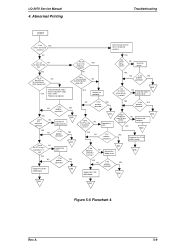
...the YES printhead broken? Connect the cable correctly. Is it OK? Are any bad parts. YES Replace the printhead.. Are the correct printer drivers installed ? Is the problem corrected ? YES END YES NO Is the YES problem corrected ? NO Dose the resistence NO of NO Reinstall...YES NO Is the YES probelm corrected? Check NO the FFC using NO a multimeter. YES NO Is the YES problem corrected ? LQ-2070 Service Manual 4. Date received from the host is not printed correctly. NO Are all NO the LEDs on the control panel blink at...
...the YES printhead broken? Connect the cable correctly. Is it OK? Are any bad parts. YES Replace the printhead.. Are the correct printer drivers installed ? Is the problem corrected ? YES END YES NO Is the YES problem corrected ? NO Dose the resistence NO of NO Reinstall...YES NO Is the YES probelm corrected? Check NO the FFC using NO a multimeter. YES NO Is the YES problem corrected ? LQ-2070 Service Manual 4. Date received from the host is not printed correctly. NO Are all NO the LEDs on the control panel blink at...


