Owners Manual
Page 1
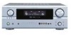
"SERIAL NO. IN MASTER VOLUME 2 We greatly appreciate your purchase of the AVR-2805/985. 2 To be sure you take maximum advantage of all the features the AVR-2805/985 has to keep this manual for future reference, should any questions or problems arise. Be sure to offer, read these instructions carefully and use the set properly. PLEASE RECORD UNIT SERIAL NUMBER ATTACHED TO THE REAR OF THE CABINET FOR FUTURE REFERENCE" AV SURROUND RECEIVER AVR-2805/985 OPERATING INSTRUCTIONS FUNCTION SOURCE TUNING PRESET ZONE 2 / REC SELECT VIDEO SELECT ON / STANDBY MODE ANALOG EXT.
"SERIAL NO. IN MASTER VOLUME 2 We greatly appreciate your purchase of the AVR-2805/985. 2 To be sure you take maximum advantage of all the features the AVR-2805/985 has to keep this manual for future reference, should any questions or problems arise. Be sure to offer, read these instructions carefully and use the set properly. PLEASE RECORD UNIT SERIAL NUMBER ATTACHED TO THE REAR OF THE CABINET FOR FUTURE REFERENCE" AV SURROUND RECEIVER AVR-2805/985 OPERATING INSTRUCTIONS FUNCTION SOURCE TUNING PRESET ZONE 2 / REC SELECT VIDEO SELECT ON / STANDBY MODE ANALOG EXT.
Owners Manual
Page 4
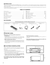
... using microprocessors is provided with an immense array of features, we recommend that before you begin hookup and operation that you for choosing the DENON AVR-2805/985 Digital A / V Surround Receiver. TABLE OF CONTENTS z Before Using 4 x Cautions on Installation 4 c Cautions on Check once again that all other components. 4 inch/10 cm or more 4 inch/10...
... using microprocessors is provided with an immense array of features, we recommend that before you begin hookup and operation that you for choosing the DENON AVR-2805/985 Digital A / V Surround Receiver. TABLE OF CONTENTS z Before Using 4 x Cautions on Installation 4 c Cautions on Check once again that all other components. 4 inch/10 cm or more 4 inch/10...
Owners Manual
Page 5
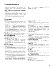
...subroom (ZONE2) simultaneously. 10.Future Sound Format Upgrade Capability via Eight Channel Inputs & Outputs For future multi-channel audio format(s), the AVR-2805/985 is provided with 7.1 channel (seven main channels, plus one set of 7.1 channel pre-amp outputs, controlled by Digital Theater Systems...assures future upgrade possibilities for any other-set of component video outputs to the television, for superior picture quality. 14.TRIGGER OUT AVR-2805/985 is a function for delaying the audio signal with DTS-ES Extended Surround, a multi-channel format developed by the 8 channel master...
...subroom (ZONE2) simultaneously. 10.Future Sound Format Upgrade Capability via Eight Channel Inputs & Outputs For future multi-channel audio format(s), the AVR-2805/985 is provided with 7.1 channel (seven main channels, plus one set of 7.1 channel pre-amp outputs, controlled by Digital Theater Systems...assures future upgrade possibilities for any other-set of component video outputs to the television, for superior picture quality. 14.TRIGGER OUT AVR-2805/985 is a function for delaying the audio signal with DTS-ES Extended Surround, a multi-channel format developed by the 8 channel master...
Owners Manual
Page 7
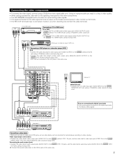
... IN OUT IN AUDIO VIDEO Note on connecting the digital input jacks • Only audio signals are two sets of the other components. • The AVR-2805/985 is output to the VCR-2 jacks in the same way. Connect the second video deck to the S-Video and component video monitor out terminals. •...
... IN OUT IN AUDIO VIDEO Note on connecting the digital input jacks • Only audio signals are two sets of the other components. • The AVR-2805/985 is output to the VCR-2 jacks in the same way. Connect the second video deck to the S-Video and component video monitor out terminals. •...
Owners Manual
Page 8
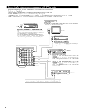
... the S-VIDEO VCR-2 OUT jack using a S-Video connection cord. • VDP can be connected to the VDP jacks in conjunction with each other. • The AVR-2805/985 is equipped with a function for converting video signals. • The signal connected to the S-Video signal terminal is also possible to connect a video disc player...
... the S-VIDEO VCR-2 OUT jack using a S-Video connection cord. • VDP can be connected to the VDP jacks in conjunction with each other. • The AVR-2805/985 is equipped with a function for converting video signals. • The signal connected to the S-Video signal terminal is also possible to connect a video disc player...
Owners Manual
Page 9
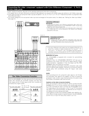
...the VTR, or if your VTR has a TBC function, turn it on. (Video jack) (Video jack) 9 MONITOR OUT jacks The AVR-2805/985 is not possible, so when not using the component video monitor output terminal connect the player using 75 Ω/ohms coaxial video pin-plug ...for up-converting video signals. NOTE: Down-converting from the component video signal to the VIDEO-2 color difference (component) video jacks. Because of this, the AVR-2805/985's MONITOR OUT jack can be out of the other component. For details, see "Setting the Video Input Mode". (See page 41) COMPONENT VIDEO OUT ...
...the VTR, or if your VTR has a TBC function, turn it on. (Video jack) (Video jack) 9 MONITOR OUT jacks The AVR-2805/985 is not possible, so when not using the component video monitor output terminal connect the player using 75 Ω/ohms coaxial video pin-plug ...for up-converting video signals. NOTE: Down-converting from the component video signal to the VIDEO-2 color difference (component) video jacks. Because of this, the AVR-2805/985's MONITOR OUT jack can be out of the other component. For details, see "Setting the Video Input Mode". (See page 41) COMPONENT VIDEO OUT ...
Owners Manual
Page 18
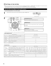
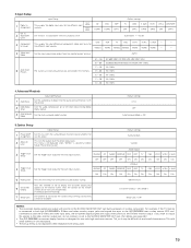
... Configuration corresponding sizes (SMALL for regular speakers, LARGE for fullsize, full-range) to automatically set up the listening room's AV system centered around the AVR-2805/985. Default settings Subwoofer Surround Sp. These settings are required to set the composition of the signals output from the speakers and... mode is in order to obtain optimum effects. 4 Crossover Frequency Set the frequency (Hz) below on the monitor screen using the AVR-2805/985's on the screen ENTER button Press this to switch the Mic Input jack for use for zone2. 2 Manual EQ Setup This parameter...
... Configuration corresponding sizes (SMALL for regular speakers, LARGE for fullsize, full-range) to automatically set up the listening room's AV system centered around the AVR-2805/985. Default settings Subwoofer Surround Sp. These settings are required to set the composition of the signals output from the speakers and... mode is in order to obtain optimum effects. 4 Crossover Frequency Set the frequency (Hz) below on the monitor screen using the AVR-2805/985's on the screen ENTER button Press this to switch the Mic Input jack for use for zone2. 2 Manual EQ Setup This parameter...
Owners Manual
Page 19
...output with small screens or low resolutions. • The setup menu is connected to both the AVR-2805/985's S-Video and video monitor output jacks and signals are input to the AVR-2805/985 from the monitor output terminal. Input source Digital Inputs CD DVD VDP COAX1 COAX2 OPT1 Default settings...Option Setup Option Setup Default settings 1 Power AMP Assignment Set this to read small characters on the remote control unit or main unit are received automatically and stored in the memory. Set whether or not to delay time the sound and synchronize it may be changed. 3.Input Setup...
...output with small screens or low resolutions. • The setup menu is connected to both the AVR-2805/985's S-Video and video monitor output jacks and signals are input to the AVR-2805/985 from the monitor output terminal. Input source Digital Inputs CD DVD VDP COAX1 COAX2 OPT1 Default settings...Option Setup Option Setup Default settings 1 Power AMP Assignment Set this to read small characters on the remote control unit or main unit are received automatically and stored in the memory. Set whether or not to delay time the sound and synchronize it may be changed. 3.Input Setup...
Owners Manual
Page 28
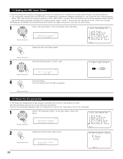
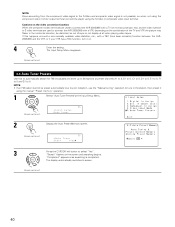
... setup procedure using a microphone other than the included one for measurements when performing the auto setup procedure. • The microphone included with the AVR-2805 is a measurement microphone designed specifically for measurements, select "V.AUX L" and connect the microphone to the "SETUP MIC" mini-jack. The Auto...the "Auto Setup / Room EQ" is unified. The EQ parameters that were set in Auto Setup can be checked. Please ask the DENON Authorized Service Center about the usable microphone other than the option setup. 1 Select "Mic Input Select" at the Auto Setup / Room EQ...
... setup procedure using a microphone other than the included one for measurements when performing the auto setup procedure. • The microphone included with the AVR-2805 is a measurement microphone designed specifically for measurements, select "V.AUX L" and connect the microphone to the "SETUP MIC" mini-jack. The Auto...the "Auto Setup / Room EQ" is unified. The EQ parameters that were set in Auto Setup can be checked. Please ask the DENON Authorized Service Center about the usable microphone other than the option setup. 1 Select "Mic Input Select" at the Auto Setup / Room EQ...
Owners Manual
Page 32
... can also be 20 ft (6.0 m) or less. In this setting to adjust so that the playback level between the center speaker and listening position. The AVR-2805/985 automatically sets the optimum surround delay time for every speaker should be adjusted directly from the speakers to the default values. The Speaker Setup Menu...
... can also be 20 ft (6.0 m) or less. In this setting to adjust so that the playback level between the center speaker and listening position. The AVR-2805/985 automatically sets the optimum surround delay time for every speaker should be adjusted directly from the speakers to the default values. The Speaker Setup Menu...
Owners Manual
Page 37
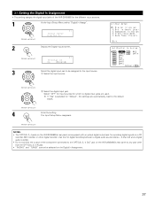
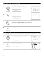
...digital recording between a digital audio source (stereo - 2 channel) and a digital audio recorder. • Do not connect the output of the AVR-2805/985 for which no digital input jacks are automatically reset to the default values. (Remote control unit) 4 Enter the setting. 3-1 Setting the Digital ...In Assignment • This setting assigns the digital input jacks of the component connected to the OPTICAL 3, 4 OUT jack on the AVR-2805/985's rear panel to any jack other digital recorder. If "Yes" is selected for recording digital signals on the Digital In Assignment. 37...
...digital recording between a digital audio source (stereo - 2 channel) and a digital audio recorder. • Do not connect the output of the AVR-2805/985 for which no digital input jacks are automatically reset to the default values. (Remote control unit) 4 Enter the setting. 3-1 Setting the Digital ...In Assignment • This setting assigns the digital input jacks of the component connected to the OPTICAL 3, 4 OUT jack on the AVR-2805/985's rear panel to any jack other digital recorder. If "Yes" is selected for recording digital signals on the Digital In Assignment. 37...
Owners Manual
Page 38
... Input Setup Menu reappears. (Remote control unit) 3-3 Setting the Component In Assign • This setting assigns the color difference (component) video input jacks of the AVR-2805/985 for the different input sources. 1 Select "Component In Assign" at the Input Setup Menu. (Remote control unit) *Input Setup Ext.In SW Lev. 2 Display to...
... Input Setup Menu reappears. (Remote control unit) 3-3 Setting the Component In Assign • This setting assigns the color difference (component) video input jacks of the AVR-2805/985 for the different input sources. 1 Select "Component In Assign" at the Input Setup Menu. (Remote control unit) *Input Setup Ext.In SW Lev. 2 Display to...
Owners Manual
Page 40
... conversion function: When the component video terminals are used to connect the AVR-2805/985 with a TV (or monitor, projector, etc.) and the video (yellow) or S video terminals are used to connect the AVR-2805/985 with a TBC (time base corrector) function between the AVR2805/985 and the VTR, or if your VTR has a TBC function, turn...
... conversion function: When the component video terminals are used to connect the AVR-2805/985 with a TV (or monitor, projector, etc.) and the video (yellow) or S video terminals are used to connect the AVR-2805/985 with a TBC (time base corrector) function between the AVR2805/985 and the VTR, or if your VTR has a TBC function, turn...
Owners Manual
Page 47
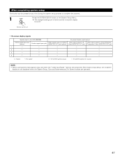
... the SYSTEM SETUP button at Input setup, the on -screen display turns off. (Remote control unit) • On-screen display signals Signals input to the AVR-2805/985 On-screen display signal output VIDEO signal input jack (yellow) S-video signal input jack Video signal output to VIDEO MONITOR OUT jack (yellow) Video signal...
... the SYSTEM SETUP button at Input setup, the on -screen display turns off. (Remote control unit) • On-screen display signals Signals input to the AVR-2805/985 On-screen display signal output VIDEO signal input jack (yellow) S-video signal input jack Video signal output to VIDEO MONITOR OUT jack (yellow) Video signal...
Owners Manual
Page 48
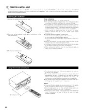
...30° 48 • Point the remote control unit at a horizontal angle of up to 30 degrees with respect to operate not only the AVR-2805/985 but this depends on the main unit and remote control unit simultaneously. e Put the rear cover back on the diagram. • The remote control...• When replacing the batteries, have the new batteries ready and insert them as quickly as possible. Replace it can be used to operate non-Denon remote control compatible products. 8 REMOTE CONTROL UNIT • The included remote control unit (RC-974) can be used from a straight distance of ...
...30° 48 • Point the remote control unit at a horizontal angle of up to 30 degrees with respect to operate not only the AVR-2805/985 but this depends on the main unit and remote control unit simultaneously. e Put the rear cover back on the diagram. • The remote control...• When replacing the batteries, have the new batteries ready and insert them as quickly as possible. Replace it can be used to operate non-Denon remote control compatible products. 8 REMOTE CONTROL UNIT • The included remote control unit (RC-974) can be used from a straight distance of ...
Owners Manual
Page 59
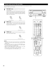
... the analog mode Press the ANALOG button to switch to the analog input. Select the AUTO or DTS mode when playing signals recorded in the AVR-2805/985's surround decoder is selected automatically upon playback. w PCM (exclusive PCM signal playback mode) Decoding and playback are only performed when PCM signals are being input...
... the analog mode Press the ANALOG button to switch to the analog input. Select the AUTO or DTS mode when playing signals recorded in the AVR-2805/985's surround decoder is selected automatically upon playback. w PCM (exclusive PCM signal playback mode) Decoding and playback are only performed when PCM signals are being input...
Owners Manual
Page 62
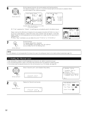
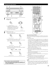
... while watching images. 1 (Remote control unit) 2 3 NOTES: • The system setup function cannot be reproduced with high quality. Playing audio sources (CDs and DVDs) The AVR-2805/985 is set to "OFF" in order to turn off so that music signals can be used when the PURE DIRECT mode is equipped with three...
... while watching images. 1 (Remote control unit) 2 3 NOTES: • The system setup function cannot be reproduced with high quality. Playing audio sources (CDs and DVDs) The AVR-2805/985 is set to "OFF" in order to turn off so that music signals can be used when the PURE DIRECT mode is equipped with three...
Owners Manual
Page 65
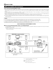
The AVR-2805/985 is equipped with multi-source MULTI ZONE MUSIC ENTERTAINMENT SYSTEM • When the outputs of separately sold ) control line MULTI SOURCE AUDIO signal cable ZONE2 ... REMOTE CONTROL SYSTEM (separately sold devices, refer to the devices' operating instructions. • When the PURE DIRECT mode is set to -room remote control unit (DENON RC-616, 617 or 618) is wired and connected between the MAIN ZONE and ZONE2, the remote-controllable devices in such a way that device's remote...
The AVR-2805/985 is equipped with multi-source MULTI ZONE MUSIC ENTERTAINMENT SYSTEM • When the outputs of separately sold ) control line MULTI SOURCE AUDIO signal cable ZONE2 ... REMOTE CONTROL SYSTEM (separately sold devices, refer to the devices' operating instructions. • When the PURE DIRECT mode is set to -room remote control unit (DENON RC-616, 617 or 618) is wired and connected between the MAIN ZONE and ZONE2, the remote-controllable devices in such a way that device's remote...

Owners Manual
Page 66
... ZONE2 output terminals. (1) System configuration and connections example. Using this case, Surround Back PREOUT and speaker out cannot be used for MAIN ZONE. • The AVR-2805/985 is equipped with preout terminals for which the volume is adjustable (ZONE2) and speaker out terminals for which the volume is selected at System Setup...
... ZONE2 output terminals. (1) System configuration and connections example. Using this case, Surround Back PREOUT and speaker out cannot be used for MAIN ZONE. • The AVR-2805/985 is equipped with preout terminals for which the volume is adjustable (ZONE2) and speaker out terminals for which the volume is selected at System Setup...

Owners Manual
Page 70
...: DOLBY PL (Dolby Pro Logic mode) 5 Select the parameter to change. (See "Surround parameters q" for a description of speakers set up to "1spkr" or "2spkrs"). The AVR-2805/985 sets the mode automatically according to "OPTION 0" using the remote control unit while in the MUSIC mode, set the " " mark to the types of each...
...: DOLBY PL (Dolby Pro Logic mode) 5 Select the parameter to change. (See "Surround parameters q" for a description of speakers set up to "1spkr" or "2spkrs"). The AVR-2805/985 sets the mode automatically according to "OPTION 0" using the remote control unit while in the MUSIC mode, set the " " mark to the types of each...


