Literature/Product Sheet
Page 1
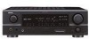
... can be controlled via the remote controller supplied with the AVR-1707. *1) Supports 3rd-generation and later iPods equipped with DENON's DSP acoustic environment simulation modes. A/V Receiver AVR-1707 DTS-ES Discrete 6.1 and Dolby Digital EX with Power Amps for 7 Channels Audio section s Fully Discrete 7-channel high power amplifier Front 75 W + 75 W (8 ohms, 20 Hz - 20 kHz, 0.08...
... can be controlled via the remote controller supplied with the AVR-1707. *1) Supports 3rd-generation and later iPods equipped with DENON's DSP acoustic environment simulation modes. A/V Receiver AVR-1707 DTS-ES Discrete 6.1 and Dolby Digital EX with Power Amps for 7 Channels Audio section s Fully Discrete 7-channel high power amplifier Front 75 W + 75 W (8 ohms, 20 Hz - 20 kHz, 0.08...
Literature/Product Sheet
Page 2
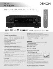
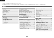
...3 Component Inputs DVD/VDP, TV/DBS, VCR Video Outputs 2 Composite Outputs VCR, MONITOR 2 S-Video Outputs VCR, MONITOR 1 Component Output MONITOR Specifications Power Amplifier Section Rated output *THD figures are easy to change without notice. *"Dolby", "Dolby Digital", "Pro Logic II", "Dolby Digital EX" and...picture that you can occur when a video signal is a trademark of delay effects and unnatural artifacts, from all of DENON's high-grade A/V receiver, the AVR-1707 lets you adjust delay times and other countries. *©2006 XM Satellite Radio Inc. and other parameters so that ...
...3 Component Inputs DVD/VDP, TV/DBS, VCR Video Outputs 2 Composite Outputs VCR, MONITOR 2 S-Video Outputs VCR, MONITOR 1 Component Output MONITOR Specifications Power Amplifier Section Rated output *THD figures are easy to change without notice. *"Dolby", "Dolby Digital", "Pro Logic II", "Dolby Digital EX" and...picture that you can occur when a video signal is a trademark of delay effects and unnatural artifacts, from all of DENON's high-grade A/V receiver, the AVR-1707 lets you adjust delay times and other countries. *©2006 XM Satellite Radio Inc. and other parameters so that ...
Owners Manual - English
Page 2
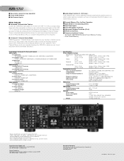
...following the operating instructions. Grounding or Polarization - This is in the literature accompanying the appliance. Unplug this product from battery power, or other controls may cause the product and cart combination to persons. Unauthorized substitutions may fall into the outlet, try...and should be read before cleaning. Object and Liquid Entry - Read Instructions - Heed Warnings - Accessories - Any mounting of overhead power lines or other hazards. 23. FIGURE A EXAMPLE OF ANTENNA GROUNDING AS PER NATIONAL ELECTRICAL CODE GROUND CLAMP ANTENNA LEAD IN WIRE ...
...following the operating instructions. Grounding or Polarization - This is in the literature accompanying the appliance. Unplug this product from battery power, or other controls may cause the product and cart combination to persons. Unauthorized substitutions may fall into the outlet, try...and should be read before cleaning. Object and Liquid Entry - Read Instructions - Heed Warnings - Accessories - Any mounting of overhead power lines or other hazards. 23. FIGURE A EXAMPLE OF ANTENNA GROUNDING AS PER NATIONAL ELECTRICAL CODE GROUND CLAMP ANTENNA LEAD IN WIRE ...
Owners Manual - English
Page 3
... requirements. If this product does cause harmful interference to radio or television reception, which the receiver is no guarantee that to which can radiate radio frequency energy and, if not installed and...to correct the interference by the FCC, to Part 15 of time. • Handle the power cord carefully. Hold the plug when unplugging the cord. * (For apparatuses with the instructions... This product complies with Canadian ICES-003. Modification not expressly approved by DENON may void your authority, granted by one or more of the following two conditions: (1) this product...
... requirements. If this product does cause harmful interference to radio or television reception, which the receiver is no guarantee that to which can radiate radio frequency energy and, if not installed and...to correct the interference by the FCC, to Part 15 of time. • Handle the power cord carefully. Hold the plug when unplugging the cord. * (For apparatuses with the instructions... This product complies with Canadian ICES-003. Modification not expressly approved by DENON may void your authority, granted by one or more of the following two conditions: (1) this product...
Owners Manual - English
Page 4
...EXT. This remarkable component has been engineered to music in the Browse mode 34 Viewing still pictures and videos (only for choosing the DENON AVR-1707 AV Surround Receiver. IN) terminals 14 Connecting a CD player 15 Connecting a tape deck, CD recorder or MD recorder 15 Connecting a VCR 15 ...17 Connecting the MULTI ZONE terminals Connecting a room-to-room remote control unit 17 ZONE2 speaker out connections 18 Connecting the power supply cord 18 Basic Operation Playing the input source 19 Turning the sound off temporarily (MUTING 20 Listening over headphones 20 Switching...
...EXT. This remarkable component has been engineered to music in the Browse mode 34 Viewing still pictures and videos (only for choosing the DENON AVR-1707 AV Surround Receiver. IN) terminals 14 Connecting a CD player 15 Connecting a tape deck, CD recorder or MD recorder 15 Connecting a VCR 15 ...17 Connecting the MULTI ZONE terminals Connecting a room-to-room remote control unit 17 ZONE2 speaker out connections 18 Connecting the power supply cord 18 Basic Operation Playing the input source 19 Turning the sound off temporarily (MUTING 20 Listening over headphones 20 Switching...
Owners Manual - English
Page 5
..., store this unit: • Moving the unit. To prevent short-circuits or damaged wires in the connection cables, always unplug the power supply cord and disconnect the connection cables between all connections are correct and that there are attached in addition to the standby position before using...Mode Setup 46 Setting the Distance 46, 47 Setting the Crossover Frequency 47 Setting the Test Tone 47 Operating the remote control unit Operating DENON audio components 48 Setting the preset memory function 48 Operating a component stored in noise. Using a mobile phone near this unit may ...
..., store this unit: • Moving the unit. To prevent short-circuits or damaged wires in the connection cables, always unplug the power supply cord and disconnect the connection cables between all connections are correct and that there are attached in addition to the standby position before using...Mode Setup 46 Setting the Distance 46, 47 Setting the Crossover Frequency 47 Setting the Test Tone 47 Operating the remote control unit Operating DENON audio components 48 Setting the preset memory function 48 Operating a component stored in noise. Using a mobile phone near this unit may ...

Owners Manual - English
Page 7
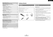
...indicators 19) @5 SIGNAL indicators 22) @6 BAND button 31) @7 EXT. o TUNED indicator This lights when an FM/AM broadcast has been received. 4 ENGLISH Getting Started Part names and functions For details on the remote control unit. • The control functions in the same way as... 33) !0 PRESET buttons 30, 31) !1 V. t Input mode indicators y ZONE2 indicator ZONE2 mode is selected in Power Amplifier Assignment. u STEREO indicator This lights when an FM stereo broadcast has been received. i AUTO indicator This lights when the broadcast station is selected in the AUTO tuning mode.
...indicators 19) @5 SIGNAL indicators 22) @6 BAND button 31) @7 EXT. o TUNED indicator This lights when an FM/AM broadcast has been received. 4 ENGLISH Getting Started Part names and functions For details on the remote control unit. • The control functions in the same way as... 33) !0 PRESET buttons 30, 31) !1 V. t Input mode indicators y ZONE2 indicator ZONE2 mode is selected in Power Amplifier Assignment. u STEREO indicator This lights when an FM stereo broadcast has been received. i AUTO indicator This lights when the broadcast station is selected in the AUTO tuning mode.
Owners Manual - English
Page 8
IN terminals 14) e DIGITAL terminals (Optical/Coaxial 9, 15) r AUDIO OUT terminals 9, 15) t Speaker terminals 8, 18, 43) y Power supply cord 18) u AC outlets 18) i COMPONENT VIDEO terminals 9) o VIDEO/S-VIDEO terminals 9) !0 DOCK CONTROL jack 17) !1 AUDIO IN terminals 9) !2 XM terminal 16)... ···(11, 22, 50) DISPLAY button 50) DIMMER/MENU button 20, 50) [ Front ] Getting Started Remote control signal transmitter 3) Power buttons 10, 50) Tuner system/System buttons 31, 32) Master volume control buttons 19) MUTING button 20) NIGHT/AUDIO button 33, 50) CH SELECT...
IN terminals 14) e DIGITAL terminals (Optical/Coaxial 9, 15) r AUDIO OUT terminals 9, 15) t Speaker terminals 8, 18, 43) y Power supply cord 18) u AC outlets 18) i COMPONENT VIDEO terminals 9) o VIDEO/S-VIDEO terminals 9) !0 DOCK CONTROL jack 17) !1 AUDIO IN terminals 9) !2 XM terminal 16)... ···(11, 22, 50) DISPLAY button 50) DIMMER/MENU button 20, 50) [ Front ] Getting Started Remote control signal transmitter 3) Power buttons 10, 50) Tuner system/System buttons 31, 32) Master volume control buttons 19) MUTING button 20) NIGHT/AUDIO button 33, 50) CH SELECT...
Owners Manual - English
Page 11
...speaker cables 1. Tighten by turning counterclockwise. If this , plug the power cord back in amplifier. ENGLISH Easy Setup Procedure ¢ Connections • With the AVR-1707, up to ten speakers can be connected for long periods of ...back speaker, connect it to cool off and improve ventilation around the unit, switch off and the power indicator blinks. Easy Setup Procedure Speaker connections Connect the speaker terminals with the speakers making connections, ...left channel. 8 ENGLISH When the protection circuit is cut off the power and contact a DENON service center.
...speaker cables 1. Tighten by turning counterclockwise. If this , plug the power cord back in amplifier. ENGLISH Easy Setup Procedure ¢ Connections • With the AVR-1707, up to ten speakers can be connected for long periods of ...back speaker, connect it to cool off and improve ventilation around the unit, switch off and the power indicator blinks. Easy Setup Procedure Speaker connections Connect the speaker terminals with the speakers making connections, ...left channel. 8 ENGLISH When the protection circuit is cut off the power and contact a DENON service center.
Owners Manual - English
Page 13
...Procedure D H F G [ON/SOURCE] [MODE SELECTOR 1] D H F G ENGLISH Easy Setup Procedure Auto Setup w Before performing the Auto Setup procedure The AVR-1707's auto setup use the attached microphone to measure the acoustic properties in the room and automatically make the optimum settings. • To make the sound...the volume to halfway and set with the receptor pointing towards the ceiling. 4 Press or [ON/SOURCE]. • The power indicator blinks green and the power turns on a camera tripod, etc., and set the crossover frequency to "AUDIO". Be sure to select the front speaker ...
...Procedure D H F G [ON/SOURCE] [MODE SELECTOR 1] D H F G ENGLISH Easy Setup Procedure Auto Setup w Before performing the Auto Setup procedure The AVR-1707's auto setup use the attached microphone to measure the acoustic properties in the room and automatically make the optimum settings. • To make the sound...the volume to halfway and set with the receptor pointing towards the ceiling. 4 Press or [ON/SOURCE]. • The power indicator blinks green and the power turns on a camera tripod, etc., and set the crossover frequency to "AUDIO". Be sure to select the front speaker ...
Owners Manual - English
Page 14
... again. Cancel: Cancel the checked measurement values. 3 Disconnect the setup mic to select "Store", then press F. Measurement of each channel is set at "Setting the Power Amplifier Assignment" ( page 43). Store: Store the checked measurement values. Measure:FL All parameters are stored. ENGLISH Easy Setup Procedure r Starting Auto Setup 1 Press F to...
... again. Cancel: Cancel the checked measurement values. 3 Disconnect the setup mic to select "Store", then press F. Measurement of each channel is set at "Setting the Power Amplifier Assignment" ( page 43). Store: Store the checked measurement values. Measure:FL All parameters are stored. ENGLISH Easy Setup Procedure r Starting Auto Setup 1 Press F to...
Owners Manual - English
Page 15
Be sure to select the items, then press F. Press D H to turn off the AVR-1707's power before checking the speaker connections. Example Caution:SP None F L Caution :Phase F L / R C a u t i o n Overload Easy Setup Procedure Error messages An error message is displayed if the measurements could not be completed automatically due to the speaker layout, the measuring environment, etc. Please check the following matters, reset the pertinent items, and measure again.
Be sure to select the items, then press F. Press D H to turn off the AVR-1707's power before checking the speaker connections. Example Caution:SP None F L Caution :Phase F L / R C a u t i o n Overload Easy Setup Procedure Error messages An error message is displayed if the measurements could not be completed automatically due to the speaker layout, the measuring environment, etc. Please check the following matters, reset the pertinent items, and measure again.
Owners Manual - English
Page 16
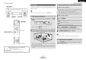
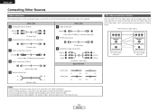
...completed. • When making connections, also refer to connect the left and right channels properly (left with left, right with right). • Do not bundle power cords together with speaker cables. Audio cable A Analog connections (Stereo) (White) (Red) L L R R Pin-plug cable B Analog connections (Monaural, for...NOTE: • Do not plug in humming or noise. (Y) (PB/CB) (PR/CR) IN IN The video conversion function With the AVR-1707, the Video signal and the S-Video signal which were inputted are mutually converted. The flow of the video signals. (Component Video terminals) ...
...completed. • When making connections, also refer to connect the left and right channels properly (left with left, right with right). • Do not bundle power cords together with speaker cables. Audio cable A Analog connections (Stereo) (White) (Red) L L R R Pin-plug cable B Analog connections (Monaural, for...NOTE: • Do not plug in humming or noise. (Y) (PB/CB) (PR/CR) IN IN The video conversion function With the AVR-1707, the Video signal and the S-Video signal which were inputted are mutually converted. The flow of the video signals. (Component Video terminals) ...
Owners Manual - English
Page 19
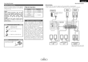
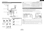
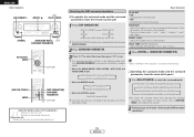
... out the connection line. 4 a. Push the lever. 2. AUX OUT NOTE: • Keep the power supply cord unplugged until the XM Passport System connection has been completed. • The XM name and ...16 ENGLISH MX Connecting Other Sources Connecting the antenna terminals An FM antenna cable plug can receive XM® Satellite Radio by connecting to the XM Passport System (sold separately) and ...system installer's attention to the point of AM antennas 1. Connecting the XM terminal • AVR-1707 is a registered trademark of the NEC which provides guidelines for proper grounding and, in the...
... out the connection line. 4 a. Push the lever. 2. AUX OUT NOTE: • Keep the power supply cord unplugged until the XM Passport System connection has been completed. • The XM name and ...16 ENGLISH MX Connecting Other Sources Connecting the antenna terminals An FM antenna cable plug can receive XM® Satellite Radio by connecting to the XM Passport System (sold separately) and ...system installer's attention to the point of AM antennas 1. Connecting the XM terminal • AVR-1707 is a registered trademark of the NEC which provides guidelines for proper grounding and, in the...

Owners Manual - English
Page 21
...) AC 120 V, 60 Hz AC OUTLETS • SWITCHED (total capacity - 120 W (1A.)) The power to the ZONE2 stereo 2 channel. Subwoofer Connection terminal for subwoofer with the POWER switch on the main unit, and when the power is switched between on and off in conjunction with built-in the generation of noise... supplied from the remote control unit. Never use the AC OUTLETS for MAIN ZONE. In this unit's power is at Power Amplifier Assignment mode, the surround back speaker terminals can not be used for audio equipment. Incomplete connections will result in amplifier. NOTE: •...
...) AC 120 V, 60 Hz AC OUTLETS • SWITCHED (total capacity - 120 W (1A.)) The power to the ZONE2 stereo 2 channel. Subwoofer Connection terminal for subwoofer with the POWER switch on the main unit, and when the power is switched between on and off in conjunction with built-in the generation of noise... supplied from the remote control unit. Never use the AC OUTLETS for MAIN ZONE. In this unit's power is at Power Amplifier Assignment mode, the surround back speaker terminals can not be used for audio equipment. Incomplete connections will result in amplifier. NOTE: •...
Owners Manual - English
Page 32
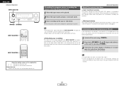
ENGLISH Basic Operation F G, SELECT/ENTER , D H SURROUND PARAMETER [CH SELECT], ENTER D H F G [5CH/7CH STEREO] ENTER [DSP SIMULATION] SURROUND PARAMETER D H F G About the button names in this explanation < > : Buttons on the main unit [ ] : Buttons on the remote control unit Button name only : Buttons on the main unit and remote control unit Selecting the DSP surround simulation ¢ To operate the surround mode and the surround parameters from the main unit's panel 1 Use to select the surround mode. Basic Operation SB CH OUT • ON: Surround back channel played. •...
ENGLISH Basic Operation F G, SELECT/ENTER , D H SURROUND PARAMETER [CH SELECT], ENTER D H F G [5CH/7CH STEREO] ENTER [DSP SIMULATION] SURROUND PARAMETER D H F G About the button names in this explanation < > : Buttons on the main unit [ ] : Buttons on the remote control unit Button name only : Buttons on the main unit and remote control unit Selecting the DSP surround simulation ¢ To operate the surround mode and the surround parameters from the main unit's panel 1 Use to select the surround mode. Basic Operation SB CH OUT • ON: Surround back channel played. •...
Owners Manual - English
Page 33
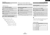
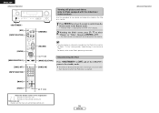
ENGLISH Basic Operation Setting the tone control Adjust the bass and treble to suit your tastes. ¢ Adjusting the tone 1 Press SURROUND PARAMETER. 2 Press D H to "AUDIO". OFF ´ -12.0 dB ´ +12.0 dB Basic Operation Listening to the radio Check that station is stored in after the auto preset memory operation is completed. 1 ROOM SIZE MED 2 TONE DEF. Subsequent stations are automatically stored in order at preset channels A1 to A8, B1 to B8, C1 to C8, D1 to D8, E1 to E8, F1 to F8 and G1 to G8 for FM broadcast stations. Channel A1 is set the level. OFF 4 B A S...
ENGLISH Basic Operation Setting the tone control Adjust the bass and treble to suit your tastes. ¢ Adjusting the tone 1 Press SURROUND PARAMETER. 2 Press D H to "AUDIO". OFF ´ -12.0 dB ´ +12.0 dB Basic Operation Listening to the radio Check that station is stored in after the auto preset memory operation is completed. 1 ROOM SIZE MED 2 TONE DEF. Subsequent stations are automatically stored in order at preset channels A1 to A8, B1 to B8, C1 to C8, D1 to D8, E1 to E8, F1 to F8 and G1 to G8 for FM broadcast stations. Channel A1 is set the level. OFF 4 B A S...
Owners Manual - English
Page 38
... on a monitor. 1 Press [MODE] for at least 2 seconds to switch from the Browse mode to the Remote mode. • "Remote iPod" is displayed on the AVR-1707's display. 2 Watching the iPod's screen, press [D H] to select "Photos" or "Video", then press [ENTER] or [G]. • The iPod's photo and video data are displayed on... remote control unit Button name only : Buttons on the iPod to the monitor, the iPod's "TV Out" setting (under "Video Settings") must be set the AVR-1707's power to the standby mode.
... on a monitor. 1 Press [MODE] for at least 2 seconds to switch from the Browse mode to the Remote mode. • "Remote iPod" is displayed on the AVR-1707's display. 2 Watching the iPod's screen, press [D H] to select "Photos" or "Video", then press [ENTER] or [G]. • The iPod's photo and video data are displayed on... remote control unit Button name only : Buttons on the iPod to the monitor, the iPod's "TV Out" setting (under "Video Settings") must be set the AVR-1707's power to the standby mode.
Owners Manual - English
Page 39
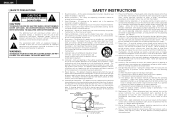
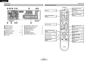
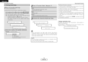
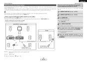
MAIN ZONE 5.1-channel systems Monitor FL DVD player B C AVR-1707 FR SW ZONE2 4 Press [INPUT SELECTOR]. Default setting (ZONE2 volume level): - - - dB (Minimum) 6 When the ZONE2 SOURCE function is only possible when the main unit ... Multi zone music entertainment system • ZONE2 speaker out can be used for MAIN ZONE. • When a sold separately room-to-room remote control unit (DENON RC-616, 617 or 618) is selected at "Power Amp Assignment".
MAIN ZONE 5.1-channel systems Monitor FL DVD player B C AVR-1707 FR SW ZONE2 4 Press [INPUT SELECTOR]. Default setting (ZONE2 volume level): - - - dB (Minimum) 6 When the ZONE2 SOURCE function is only possible when the main unit ... Multi zone music entertainment system • ZONE2 speaker out can be used for MAIN ZONE. • When a sold separately room-to-room remote control unit (DENON RC-616, 617 or 618) is selected at "Power Amp Assignment".
Owners Manual - English
Page 40
...set upon shipment from the factory). 37 ENGLISH For instructions, refer to standby are stored in the memory for about 1 week, even when the power is flashing at 1-second intervals and release the buttons. • The microprocessor will be played. 2 Select the input mode and play (surround)..., the same source can be recorded simultaneously on , the settings made when the power was switched to standby are recalled. ¢ Backup memory The various settings are connected and set when the AVR-1707's power is unplugged. • The AUDIO IN's signal selected with INPUT SELECTOR are not...
...set upon shipment from the factory). 37 ENGLISH For instructions, refer to standby are stored in the memory for about 1 week, even when the power is flashing at 1-second intervals and release the buttons. • The microprocessor will be played. 2 Select the input mode and play (surround)..., the same source can be recorded simultaneously on , the settings made when the power was switched to standby are recalled. ¢ Backup memory The various settings are connected and set when the AVR-1707's power is unplugged. • The AUDIO IN's signal selected with INPUT SELECTOR are not...


