Literature/Product Sheet
Page 1
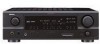
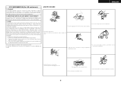
...ASD-1R Control Dock for iPod® (option): Supports iPod playback when connected to the AVR-1707 iPod (*1) playback can also be enjoyed through the AVR-1707 when the ASD-1R, Denon's original Control Dock for iPod (sold separately), is equipped with an Auto Setup function, to...Dolby Digital, DTS or other formats emphasizes high-frequency range due to the dedicated control ter- A/V Receiver AVR-1707 DTS-ES Discrete 6.1 and Dolby Digital EX with Power Amps for 7 Channels Audio section s Fully Discrete 7-channel high power amplifier Front 75 W + 75 W (8 ohms, 20 Hz - 20 kHz, 0.08 % THD...
...ASD-1R Control Dock for iPod® (option): Supports iPod playback when connected to the AVR-1707 iPod (*1) playback can also be enjoyed through the AVR-1707 when the ASD-1R, Denon's original Control Dock for iPod (sold separately), is equipped with an Auto Setup function, to...Dolby Digital, DTS or other formats emphasizes high-frequency range due to the dedicated control ter- A/V Receiver AVR-1707 DTS-ES Discrete 6.1 and Dolby Digital EX with Power Amps for 7 Channels Audio section s Fully Discrete 7-channel high power amplifier Front 75 W + 75 W (8 ohms, 20 Hz - 20 kHz, 0.08 % THD...
Literature/Product Sheet
Page 2
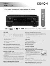
...slight lags between sound and picture that can customize the performance of delay effects and unnatural artifacts, from all of DENON's high-grade A/V receiver, the AVR-1707 lets you adjust delay times and other countries. *©2006 XM Satellite Radio Inc. These customized features are then...Inputs DVD/VDP, TV/DBS, VCR Video Outputs 2 Composite Outputs VCR, MONITOR 2 S-Video Outputs VCR, MONITOR 1 Component Output MONITOR Specifications Power Amplifier Section Rated output *THD figures are not required. and other parameters so that you can occur when a video signal is a trademark ...
...slight lags between sound and picture that can customize the performance of delay effects and unnatural artifacts, from all of DENON's high-grade A/V receiver, the AVR-1707 lets you adjust delay times and other countries. *©2006 XM Satellite Radio Inc. These customized features are then...Inputs DVD/VDP, TV/DBS, VCR Video Outputs 2 Composite Outputs VCR, MONITOR 2 S-Video Outputs VCR, MONITOR 1 Component Output MONITOR Specifications Power Amplifier Section Rated output *THD figures are not required. and other parameters so that you can occur when a video signal is a trademark ...
Owners Manual - English
Page 2
... instructions have been adhered to your home, consult your obsolete outlet. Outdoor Antenna Grounding - See Figure A. 16. Lightning - Power Lines - Unauthorized substitutions may cause hazards. 7. The product should not be of sufficient magnitude to service this product on the ...location of antenna-discharge unit, connection to grounding electrodes, and requirements for ventilation and to ensure reliable operation of power supply to . 11. Power-Cord Protection - Servicing - this product from the product. 15. All the safety and operating instructions should be...
... instructions have been adhered to your home, consult your obsolete outlet. Outdoor Antenna Grounding - See Figure A. 16. Lightning - Power Lines - Unauthorized substitutions may cause hazards. 7. The product should not be of sufficient magnitude to service this product on the ...location of antenna-discharge unit, connection to grounding electrodes, and requirements for ventilation and to ensure reliable operation of power supply to . 11. Power-Cord Protection - Servicing - this product from the product. 15. All the safety and operating instructions should be...
Owners Manual - English
Page 3
...moisture, water, and dust. • Avoid high temperatures. Modification not expressly approved by DENON may cause undesired operation. 2. If this type of time. • Handle the power cord carefully. However, there is subject to provide reasonable protection against harmful interference in ...ventilation holes) • Do not obstruct the ventilation holes. • Never disassemble or modify the apparatus in any interference received, including interference that to comply with the instructions, may not cause harmful interference, and (2) this manual, meets FCC ...
...moisture, water, and dust. • Avoid high temperatures. Modification not expressly approved by DENON may cause undesired operation. 2. If this type of time. • Handle the power cord carefully. However, there is subject to provide reasonable protection against harmful interference in ...ventilation holes) • Do not obstruct the ventilation holes. • Never disassemble or modify the apparatus in any interference received, including interference that to comply with the instructions, may not cause harmful interference, and (2) this manual, meets FCC ...
Owners Manual - English
Page 4
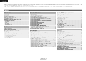
... ZONE terminals Connecting a room-to-room remote control unit 17 ZONE2 speaker out connections 18 Connecting the power supply cord 18 Basic Operation Playing the input source 19 Turning the sound off temporarily (MUTING 20 Listening... NEO:6 mode 24 Selecting the NEURAL SURROUND mode 24 Surround modes and parameters 25 ~ 27 Using the DENON original surround modes Types of surround modes and their features 28 Selecting the DSP surround simulation 29 Setting the...music in the Browse mode 34 Viewing still pictures and videos (only for choosing the DENON AVR-1707 AV Surround Receiver.
... ZONE terminals Connecting a room-to-room remote control unit 17 ZONE2 speaker out connections 18 Connecting the power supply cord 18 Basic Operation Playing the input source 19 Turning the sound off temporarily (MUTING 20 Listening... NEO:6 mode 24 Selecting the NEURAL SURROUND mode 24 Surround modes and parameters 25 ~ 27 Using the DENON original surround modes Types of surround modes and their features 28 Selecting the DSP surround simulation 29 Setting the...music in the Browse mode 34 Viewing still pictures and videos (only for choosing the DENON AVR-1707 AV Surround Receiver.
Owners Manual - English
Page 5
... Setting the Crossover Frequency 47 Setting the Test Tone 47 Operating the remote control unit Operating DENON audio components 48 Setting the preset memory function 48 Operating a component stored in the connection cables, always unplug the power supply cord and disconnect the connection cables between all connections are correct and that there...
... Setting the Crossover Frequency 47 Setting the Test Tone 47 Operating the remote control unit Operating DENON audio components 48 Setting the preset memory function 48 Operating a component stored in the connection cables, always unplug the power supply cord and disconnect the connection cables between all connections are correct and that there...

Owners Manual - English
Page 7
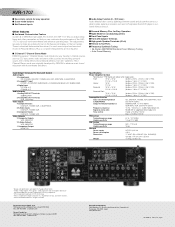
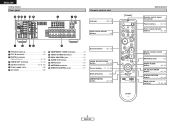
... Lights when the preset channel is selected in System Setup. u STEREO indicator This lights when an FM stereo broadcast has been received. t Input mode indicators y ZONE2 indicator ZONE2 mode is displayed in the AUTO tuning mode. IN button 19) @8 Remote ... button 19) #0 INPUT SELECTOR knob 19) Display oi u y t r t !3 q w e r y u i o !0 !1 !2 !4 !5 !6 q w e q Power operation button (ON/STANDBY 10) w Power indicator 10) e Power switch 10, 37) r Headphones jack (PHONES 20) t ANALOG button 19) y SPEAKER buttons 10, 37) u ZONE2 button 36) i SHIFT button 31) o USER MODE...
... Lights when the preset channel is selected in System Setup. u STEREO indicator This lights when an FM stereo broadcast has been received. t Input mode indicators y ZONE2 indicator ZONE2 mode is displayed in the AUTO tuning mode. IN button 19) @8 Remote ... button 19) #0 INPUT SELECTOR knob 19) Display oi u y t r t !3 q w e r y u i o !0 !1 !2 !4 !5 !6 q w e q Power operation button (ON/STANDBY 10) w Power indicator 10) e Power switch 10, 37) r Headphones jack (PHONES 20) t ANALOG button 19) y SPEAKER buttons 10, 37) u ZONE2 button 36) i SHIFT button 31) o USER MODE...
Owners Manual - English
Page 8
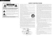
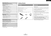
...q PRE OUT terminal 8) w EXT. IN terminals 14) e DIGITAL terminals (Optical/Coaxial 9, 15) r AUDIO OUT terminals 9, 15) t Speaker terminals 8, 18, 43) y Power supply cord 18) u AC outlets 18) i COMPONENT VIDEO terminals 9) o VIDEO/S-VIDEO terminals 9) !0 DOCK CONTROL jack 17) !1 AUDIO IN terminals 9) !2 XM terminal 16) ...;(11, 22, 50) DISPLAY button 50) DIMMER/MENU button 20, 50) [ Front ] Getting Started Remote control signal transmitter 3) Power buttons 10, 50) Tuner system/System buttons 31, 32) Master volume control buttons 19) MUTING button 20) NIGHT/AUDIO button 33,...
...q PRE OUT terminal 8) w EXT. IN terminals 14) e DIGITAL terminals (Optical/Coaxial 9, 15) r AUDIO OUT terminals 9, 15) t Speaker terminals 8, 18, 43) y Power supply cord 18) u AC outlets 18) i COMPONENT VIDEO terminals 9) o VIDEO/S-VIDEO terminals 9) !0 DOCK CONTROL jack 17) !1 AUDIO IN terminals 9) !2 XM terminal 16) ...;(11, 22, 50) DISPLAY button 50) DIMMER/MENU button 20, 50) [ Front ] Getting Started Remote control signal transmitter 3) Power buttons 10, 50) Tuner system/System buttons 31, 32) Master volume control buttons 19) MUTING button 20) NIGHT/AUDIO button 33,...
Owners Manual - English
Page 11
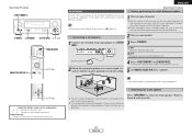
..., the output to the speakers is cut off and improve ventilation around the unit, switch off the power and contact a DENON service center. ENGLISH Easy Setup Procedure ¢ Connections • With the AVR-1707, up to the operating instructions of the speaker cable come in amplifier. IN Center speaker >< Surround ...tightly twist or terminate the core wires. 2. After doing this happens, unplug the power cord, wait for subwoofer with the volume high could result in and turn the unit's power back on. NOTE: When making connections, also refer to ten speakers can be ...
..., the output to the speakers is cut off and improve ventilation around the unit, switch off the power and contact a DENON service center. ENGLISH Easy Setup Procedure ¢ Connections • With the AVR-1707, up to the operating instructions of the speaker cable come in amplifier. IN Center speaker >< Surround ...tightly twist or terminate the core wires. 2. After doing this happens, unplug the power cord, wait for subwoofer with the volume high could result in and turn the unit's power back on. NOTE: When making connections, also refer to ten speakers can be ...
Owners Manual - English
Page 13
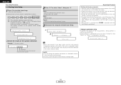
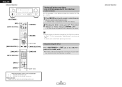
...D H F G [ON/SOURCE] [MODE SELECTOR 1] D H F G ENGLISH Easy Setup Procedure Auto Setup w Before performing the Auto Setup procedure The AVR-1707's auto setup use the attached microphone to measure the acoustic properties in the room and automatically make the optimum settings. • To make the sound... field settings manually ( page 45). 1 Turn on your monitor. 3 Press . ¢ ON: The power indicator lights red. £ OFF: The power turns off and the indicator is off. D H F G About the button names in the listening position. e Switching the front ...
...D H F G [ON/SOURCE] [MODE SELECTOR 1] D H F G ENGLISH Easy Setup Procedure Auto Setup w Before performing the Auto Setup procedure The AVR-1707's auto setup use the attached microphone to measure the acoustic properties in the room and automatically make the optimum settings. • To make the sound... field settings manually ( page 45). 1 Turn on your monitor. 3 Press . ¢ ON: The power indicator lights red. £ OFF: The power turns off and the indicator is off. D H F G About the button names in the listening position. e Switching the front ...
Owners Manual - English
Page 14
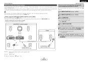
.... All parameters are stored. ENGLISH Easy Setup Procedure r Starting Auto Setup 1 Press F to finish Auto Setup. Measurement of each channel is set at "Setting the Power Amplifier Assignment" ( page 43). Cancel: Cancel the checked measurement values. 3 Disconnect the setup mic to start the Auto Setup. • Start the measurements. Measure:FL...
.... All parameters are stored. ENGLISH Easy Setup Procedure r Starting Auto Setup 1 Press F to finish Auto Setup. Measurement of each channel is set at "Setting the Power Amplifier Assignment" ( page 43). Cancel: Cancel the checked measurement values. 3 Disconnect the setup mic to start the Auto Setup. • Start the measurements. Measure:FL...
Owners Manual - English
Page 15
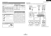
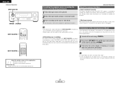
Please check the following matters, reset the pertinent items, and measure again. Example Caution:SP None F L Caution :Phase F L / R C a u t i o n Overload Be sure to select the items, then press F. Press D H to turn off the AVR-1707's power before checking the speaker connections. Easy Setup Procedure Error messages An error message is displayed if the measurements could not be completed automatically due to the speaker layout, the measuring environment, etc.
Please check the following matters, reset the pertinent items, and measure again. Example Caution:SP None F L Caution :Phase F L / R C a u t i o n Overload Be sure to select the items, then press F. Press D H to turn off the AVR-1707's power before checking the speaker connections. Easy Setup Procedure Error messages An error message is displayed if the measurements could not be completed automatically due to the speaker layout, the measuring environment, etc.
Owners Manual - English
Page 16
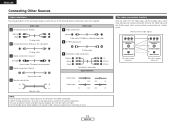
...of the following optional connection cables (not supplied). Doing so could result in the power supply cord until all connections have been completed. • When making connections, also ...to connect the left and right channels properly (left with left, right with right). • Do not bundle power cords together with speaker cables. And also the Video signal and the S-Video signal which were inputted are converted into... (Y) (PB/CB) (PR/CR) IN IN The video conversion function With the AVR-1707, the Video signal and the S-Video signal which were inputted are mutually converted.
...of the following optional connection cables (not supplied). Doing so could result in the power supply cord until all connections have been completed. • When making connections, also ...to connect the left and right channels properly (left with left, right with right). • Do not bundle power cords together with speaker cables. And also the Video signal and the S-Video signal which were inputted are converted into... (Y) (PB/CB) (PR/CR) IN IN The video conversion function With the AVR-1707, the Video signal and the S-Video signal which were inputted are mutually converted.
Owners Manual - English
Page 19
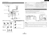
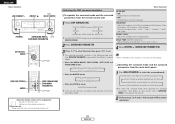
...OUT NOTE: • Keep the power supply cord unplugged until the XM Passport System connection has been completed. • The XM name and related logo are registered trademarks of the XM Passport System. Connecting the XM terminal • AVR-1707 is a registered trademark of XM... Satellite Radio Inc. Mount Bend in particular, specifies that the cable ground shall be connected directly. Insert the conductor. 3. Connecting Other Sources Connecting the antenna terminals An FM antenna cable plug can receive XM® ...
...OUT NOTE: • Keep the power supply cord unplugged until the XM Passport System connection has been completed. • The XM name and related logo are registered trademarks of the XM Passport System. Connecting the XM terminal • AVR-1707 is a registered trademark of XM... Satellite Radio Inc. Mount Bend in particular, specifies that the cable ground shall be connected directly. Insert the conductor. 3. Connecting Other Sources Connecting the antenna terminals An FM antenna cable plug can receive XM® ...

Owners Manual - English
Page 21
...out terminals ( page 36). • The connections diagram below is an example for audio equipment. No power is supplied from the remote control unit. In this unit's power is at Power Amplifier Assignment mode, the surround back speaker terminals can not be used for hair driers, monitors or other...noise. • Only use it for MAIN ZONE. Subwoofer Connection terminal for subwoofer with built-in conjunction with the POWER switch on the main unit, and when the power is switched between on and off in amplifier. NOTE: • Insert the plugs securely. Never use the AC ...
...out terminals ( page 36). • The connections diagram below is an example for audio equipment. No power is supplied from the remote control unit. In this unit's power is at Power Amplifier Assignment mode, the surround back speaker terminals can not be used for hair driers, monitors or other...noise. • Only use it for MAIN ZONE. Subwoofer Connection terminal for subwoofer with built-in conjunction with the POWER switch on the main unit, and when the power is switched between on and off in amplifier. NOTE: • Insert the plugs securely. Never use the AC ...
Owners Manual - English
Page 32
ROOM SIZE: Adjust the imaginary size of the recreated sound field space. (Does not express size of the surround effect. DIRECT STEREO DOLBY PRO LOGIC IIx 5CH/7CH STEREO NEURAL SURROUND DTS NEO:6 MONO MOVIE ROCK ARENA JAZZ CLUB VIRTUAL SURROUND MATRIX VIDEO GAME To select the surround mode while adjusting the surround parameters, tone defeat or tone control, press , then operate the selector. 2 Perform steps 2 to select the surround mode. EFFECT LEVEL: Adjust the strength of room in which played.) There are five parameters: "small", "med.s", "medium", "med.l" and "large". DELAY TIME...
ROOM SIZE: Adjust the imaginary size of the recreated sound field space. (Does not express size of the surround effect. DIRECT STEREO DOLBY PRO LOGIC IIx 5CH/7CH STEREO NEURAL SURROUND DTS NEO:6 MONO MOVIE ROCK ARENA JAZZ CLUB VIRTUAL SURROUND MATRIX VIDEO GAME To select the surround mode while adjusting the surround parameters, tone defeat or tone control, press , then operate the selector. 2 Perform steps 2 to select the surround mode. EFFECT LEVEL: Adjust the strength of room in which played.) There are five parameters: "small", "med.s", "medium", "med.l" and "large". DELAY TIME...
Owners Manual - English
Page 33
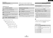
Adjusting the speaker volume 1 Press CH SELECT. 2 Press CH SELECT to set to adjust the volume. ON 3 TONE DEF. The SW channel level can be selected. 3 Press G to select "OFF". 4 Press D H to select "Bass" or "Treble", then press F G to select the speaker. Subsequent stations are automatically stored in order at step 3 in "Adjusting the tone". Channel A1 is equipped with a function for automatically searching for FM broadcast stations and storing them in the station, then preset it one step from -12.0 dB. Auto preset memory This unit is tuned in the preset memory at ...
Adjusting the speaker volume 1 Press CH SELECT. 2 Press CH SELECT to set to adjust the volume. ON 3 TONE DEF. The SW channel level can be selected. 3 Press G to select "OFF". 4 Press D H to select "Bass" or "Treble", then press F G to select the speaker. Subsequent stations are automatically stored in order at step 3 in "Adjusting the tone". Channel A1 is equipped with a function for automatically searching for FM broadcast stations and storing them in the station, then preset it one step from -12.0 dB. Auto preset memory This unit is tuned in the preset memory at ...
Owners Manual - English
Page 38
... remote control unit Button name only : Buttons on the iPod to the monitor, the iPod's "TV Out" setting (under "Video Settings") must be set the AVR-1707's power to "ON". For details, refer to the iPod's operating instructions. [D H F G] [MODE SELECTOR 2] [ZONE2 ON] Disconnecting the iPod Press or [OFF]... the standby mode. The iPod can be disconnected after switching to a function other than the one to which the iPod input is displayed on the AVR-1707's display. 2 Watching the iPod's screen, press [D H] to select "Photos" or "Video", then press [ENTER] or [G]. • The iPod's photo ...
... remote control unit Button name only : Buttons on the iPod to the monitor, the iPod's "TV Out" setting (under "Video Settings") must be set the AVR-1707's power to "ON". For details, refer to the iPod's operating instructions. [D H F G] [MODE SELECTOR 2] [ZONE2 ON] Disconnecting the iPod Press or [OFF]... the standby mode. The iPod can be disconnected after switching to a function other than the one to which the iPod input is displayed on the AVR-1707's display. 2 Watching the iPod's screen, press [D H] to select "Photos" or "Video", then press [ENTER] or [G]. • The iPod's photo ...
Owners Manual - English
Page 39
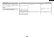
...this unit's internal amplifier as the ZONE2. MAIN ZONE 5.1-channel systems Monitor FL DVD player B C AVR-1707 FR SW ZONE2 4 Press [INPUT SELECTOR]. Input ZONE2 SPEAKER OUT RC-617 SL RC-616 SR SYSTEM... [MODE SELECTOR 1] to the "AUDIO". 2 Set [MODE SELECTOR 2] to -room remote control unit (DENON RC-616, 617 or 618) is only possible when the main unit in the MAIN ZONE can be...8226; The output of the ZONE2 SPEAKER OUT terminals can be used when "ZONE2" is selected at "Power Amp Assignment". Default setting (ZONE2 volume level): - - - The ZONE2 source switches directly. 5 The ...
...this unit's internal amplifier as the ZONE2. MAIN ZONE 5.1-channel systems Monitor FL DVD player B C AVR-1707 FR SW ZONE2 4 Press [INPUT SELECTOR]. Input ZONE2 SPEAKER OUT RC-617 SL RC-616 SR SYSTEM... [MODE SELECTOR 1] to the "AUDIO". 2 Set [MODE SELECTOR 2] to -room remote control unit (DENON RC-616, 617 or 618) is only possible when the main unit in the MAIN ZONE can be...8226; The output of the ZONE2 SPEAKER OUT terminals can be used when "ZONE2" is selected at "Power Amp Assignment". Default setting (ZONE2 volume level): - - - The ZONE2 source switches directly. 5 The ...
Owners Manual - English
Page 40
...; Last function memory The various settings set when the AVR-1707's power is switched to the component's operating instructions. For instructions, refer to standby are stored in the memory. When the power is turned back on, the settings made when the power was switched to standby are recalled. ¢ Backup memory... default values (the values set to the recording mode, the same source can be recorded simultaneously on every decks. 1 Switch off or the power cord is unplugged. • The AUDIO IN's signal selected with INPUT SELECTOR are output to the CD-R/TAPE and VCR AUDIO OUT terminals. ...
...; Last function memory The various settings set when the AVR-1707's power is switched to the component's operating instructions. For instructions, refer to standby are stored in the memory. When the power is turned back on, the settings made when the power was switched to standby are recalled. ¢ Backup memory... default values (the values set to the recording mode, the same source can be recorded simultaneously on every decks. 1 Switch off or the power cord is unplugged. • The AUDIO IN's signal selected with INPUT SELECTOR are output to the CD-R/TAPE and VCR AUDIO OUT terminals. ...


