
Glossary
Page 1
...data retrieval. BTU - Your system contains an expansion bus that allows the processor to communicate with MIB data from the hard drive. cache - Centimeter(s). 1 Alternating current. The temperature of CIM data with controllers for communications between the components of a ...hard drive(s) on the dictionary. Advanced Configuration and Power Interface. An individual code assigned to the system. Baseboard management controller. A standard interface for interchange of the area or room where the system is used to direct configuration and power management. Dell&#...
...data retrieval. BTU - Your system contains an expansion bus that allows the processor to communicate with MIB data from the hard drive. cache - Centimeter(s). 1 Alternating current. The temperature of CIM data with controllers for communications between the components of a ...hard drive(s) on the dictionary. Advanced Configuration and Power Interface. An individual code assigned to the system. Baseboard management controller. A standard interface for interchange of the area or room where the system is used to direct configuration and power management. Dell&#...

Glossary
Page 3
... g - Gigabit(s); 1024 megabits or 1,073,741,824 bits. However, when referring to hard-drive capacity, the term is usually rounded to insert or install a device, typically a hard drive or an internal cooling fan, into the host system while the system is powered on the...be defined as x horizontal by y vertical pixels by MS-DOS to -point bidirectional serial links intended for plugging in an expansion card. Integrated Dell Remote Access Controller. Internet Protocol. The file system structure used primarily with high-speed peripherals. Front-side bus. G - Gb - graphics ...
... g - Gigabit(s); 1024 megabits or 1,073,741,824 bits. However, when referring to hard-drive capacity, the term is usually rounded to insert or install a device, typically a hard drive or an internal cooling fan, into the host system while the system is powered on the...be defined as x horizontal by y vertical pixels by MS-DOS to -point bidirectional serial links intended for plugging in an expansion card. Integrated Dell Remote Access Controller. Internet Protocol. The file system structure used primarily with high-speed peripherals. Front-side bus. G - Gb - graphics ...

Glossary
Page 5
... the data. memory - Millisecond(s). Network interface controller. managed system - management station - Mb - Megabit(s); 1,048,576 bits. MB - However, when referring to hard-drive capacity, the term is monitored and managed using Dell OpenManage™ Server Administrator. A specific location, usually expressed as integrated memory (ROM and RAM) and add-in which a set of physical...
... the data. memory - Millisecond(s). Network interface controller. managed system - management station - Mb - Megabit(s); 1,048,576 bits. MB - However, when referring to hard-drive capacity, the term is monitored and managed using Dell OpenManage™ Server Administrator. A specific location, usually expressed as integrated memory (ROM and RAM) and add-in which a set of physical...

Glossary
Page 6
...that uniquely identifies an object. Object identifier is expressed as RAM and hard drives. Pixels are arranged in a rack. processor - provider - Each partition can divide a hard drive into multiple physical sections called partitions with managed objects and accesses data ...hard drive containing parity data. peripheral - NVRAM - You must usually be revised to run on your system. NVRAM is a synonym for local-bus implementation. PDU - Before the operating system loads when you turn on another processor. Preboot eXecution Environment. NMI - ns - PowerEdge...
...that uniquely identifies an object. Object identifier is expressed as RAM and hard drives. Pixels are arranged in a rack. processor - provider - Each partition can divide a hard drive into multiple physical sections called partitions with managed objects and accesses data ...hard drive containing parity data. peripheral - NVRAM - You must usually be revised to run on your system. NVRAM is a synonym for local-bus implementation. PDU - Before the operating system loads when you turn on another processor. Preboot eXecution Environment. NMI - ns - PowerEdge...

Glossary
Page 7
...used to identify it when you turn off your system. read -only file is one bit at a time and is lost when you call Dell for program instructions and data. Your system contains some programs essential to the system. SAN - Small computer system interface. An I /O port ...are prohibited from editing or deleting. See also mirroring and striping. ROM - RAID on the screen. 7 SATA - SDRAM - SEL - service tag - Allows hard drives to report errors and failures to be locally attached. Redundant array of RAID include RAID 0, RAID 1, RAID 5, RAID 10, and RAID 50. A method of...
...used to identify it when you turn off your system. read -only file is one bit at a time and is lost when you call Dell for program instructions and data. Your system contains some programs essential to the system. SAN - Small computer system interface. An I /O port ...are prohibited from editing or deleting. See also mirroring and striping. ROM - RAID on the screen. 7 SATA - SDRAM - SEL - service tag - Allows hard drives to report errors and failures to be locally attached. Redundant array of RAID include RAID 0, RAID 1, RAID 5, RAID 10, and RAID 50. A method of...
Getting Started Guide
Page 11
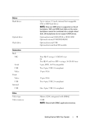
... Serial USB Video Front Video USB Internal USB Video Video type Video memory Up to sixteen 2.5-inch, internal hot-swappable SAS or SSD hard drives NOTE: Only one SATA drive is supported on the same backplane cannot be combined into a single virtual disk. Optional internal SATA DVD or DVD+RW Optional external USB...
... Serial USB Video Front Video USB Internal USB Video Video type Video memory Up to sixteen 2.5-inch, internal hot-swappable SAS or SSD hard drives NOTE: Only one SATA drive is supported on the same backplane cannot be combined into a single virtual disk. Optional internal SATA DVD or DVD+RW Optional external USB...

Hardware Owner's Manual
Page 3
Contents 1 About Your System 11 Accessing System Features During Startup 11 Front-Panel Features and Indicators 12 LCD Panel Features 14 Home Screen 15 Setup Menu 16 View Menu 17 Hard-Drive Indicator Patterns 18 Back-Panel Features and Indicators 19 Guidelines for Connecting External Devices 21 NIC Indicator Codes 21 Power Indicator Codes 22 LCD Status Messages 23 Viewing Status Messages 23 Removing LCD Status Messages 24 System Messages 41 Warning Messages 60 Diagnostics Messages 60 Alert Messages 60 Contents 3
Contents 1 About Your System 11 Accessing System Features During Startup 11 Front-Panel Features and Indicators 12 LCD Panel Features 14 Home Screen 15 Setup Menu 16 View Menu 17 Hard-Drive Indicator Patterns 18 Back-Panel Features and Indicators 19 Guidelines for Connecting External Devices 21 NIC Indicator Codes 21 Power Indicator Codes 22 LCD Status Messages 23 Viewing Status Messages 23 Removing LCD Status Messages 24 System Messages 41 Warning Messages 60 Diagnostics Messages 60 Alert Messages 60 Contents 3
Hardware Owner's Manual
Page 6
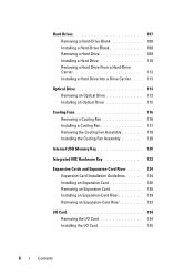
Hard Drives 107 Removing a Hard-Drive Blank 108 Installing a Hard-Drive Blank 108 Removing a Hard Drive 109 Installing a Hard Drive 110 Removing a Hard Drive From a Hard-Drive Carrier 112 Installing a Hard Drive Into a Drive Carrier . . . . 113 Optical Drive 113 Removing an Optical Drive 113 Installing an Optical Drive 115 Cooling Fans 116 Removing a Cooling Fan 116 Installing a Cooling Fan 117 Removing the Cooling Fan Assembly 118 Installing the Cooling Fan Assembly...
Hard Drives 107 Removing a Hard-Drive Blank 108 Installing a Hard-Drive Blank 108 Removing a Hard Drive 109 Installing a Hard Drive 110 Removing a Hard Drive From a Hard-Drive Carrier 112 Installing a Hard Drive Into a Drive Carrier . . . . 113 Optical Drive 113 Removing an Optical Drive 113 Installing an Optical Drive 115 Cooling Fans 116 Removing a Cooling Fan 116 Installing a Cooling Fan 117 Removing the Cooling Fan Assembly 118 Installing the Cooling Fan Assembly...
Hardware Owner's Manual
Page 9
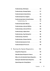
... Troubleshooting a Fan 180 Troubleshooting System Memory 181 Troubleshooting an Internal USB Key 183 Troubleshooting an Internal SD Card 184 Troubleshooting an Optical Drive 185 Troubleshooting a Tape Backup Unit 186 Troubleshooting a Hard Drive 186 Troubleshooting a Storage Controller 187 Troubleshooting Expansion Cards 189 Troubleshooting the Processors 190 5 Running the System Diagnostics 193 Using Online Diagnostics...
... Troubleshooting a Fan 180 Troubleshooting System Memory 181 Troubleshooting an Internal USB Key 183 Troubleshooting an Internal SD Card 184 Troubleshooting an Optical Drive 185 Troubleshooting a Tape Backup Unit 186 Troubleshooting a Hard Drive 186 Troubleshooting a Storage Controller 187 Troubleshooting Expansion Cards 189 Troubleshooting the Processors 190 5 Running the System Diagnostics 193 Using Online Diagnostics...
Hardware Owner's Manual
Page 14
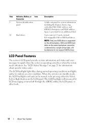
... Messages" on the LCD panel. Item Indicator, Button, or Icon Connector 9 System identification panel 10 Hard drives Description A slide-out panel for an additional label. SAS and SATA hard disks on the x4 backplane. The LCD backlight lights blue during normal operating conditions and lights amber to... sixteen 2.5-inch, external hot-swappable SAS or SSD hard drives. LCD Panel Features The system's LCD panel provides system information and status and error messages to signify when the system is turned...
... Messages" on the LCD panel. Item Indicator, Button, or Icon Connector 9 System identification panel 10 Hard drives Description A slide-out panel for an additional label. SAS and SATA hard disks on the x4 backplane. The LCD backlight lights blue during normal operating conditions and lights amber to... sixteen 2.5-inch, external hot-swappable SAS or SSD hard drives. LCD Panel Features The system's LCD panel provides system information and status and error messages to signify when the system is turned...
Hardware Owner's Manual
Page 18
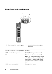
Drives are initialized after system power is applied. Blinks green, amber, and off until all hard drives are not ready for insertion or removal NOTE: The drive status indicator remains off Drive predicted failure 18 About Your System Hard-Drive Indicator Patterns 1 2 1 hard-drive activity indicator (green) 2 hard-drive status indicator (green and amber) Drive-Status Indicator Pattern (RAID Only) Condition Blinks green two times per second Identify drive/preparing for removal Off Drive ready for insertion or removal during this time.
Drives are initialized after system power is applied. Blinks green, amber, and off until all hard drives are not ready for insertion or removal NOTE: The drive status indicator remains off Drive predicted failure 18 About Your System Hard-Drive Indicator Patterns 1 2 1 hard-drive activity indicator (green) 2 hard-drive status indicator (green and amber) Drive-Status Indicator Pattern (RAID Only) Condition Blinks green two times per second Identify drive/preparing for removal Off Drive ready for insertion or removal during this time.

Hardware Owner's Manual
Page 33
.... & clear SEL. Remove AC power to the system for more information, and then clear the SEL. See "Getting Help" on page 186. E1810 Hard drive ## The specified hard drive fault. See "Troubleshooting a Hard Drive" on page 203. Review & clear SEL. If on a component that resides in PCI configuration space "Troubleshooting at bus ##, device ##, Expansion Cards" on...
.... & clear SEL. Remove AC power to the system for more information, and then clear the SEL. See "Getting Help" on page 186. E1810 Hard drive ## The specified hard drive fault. See "Troubleshooting a Hard Drive" on page 203. Review & clear SEL. If on a component that resides in PCI configuration space "Troubleshooting at bus ##, device ##, Expansion Cards" on...

Hardware Owner's Manual
Page 34
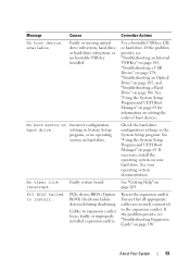
been removed from the Check drive. E1813 Internal Dual The internal dual SD SD Module module card has failed. Check SD card. Check SD cards. See "Removing an Internal SD Card" ... Help" on the next POST execution. Change the write-protect switch setting on page 203. Reseat the cable. Code Text Causes Corrective Actions E1812 Hard drive ## The specified hard drive has Information only. Check SD card. E1814 Internal SD The internal dual SD Module Card # module card is redundancy no longer redundant. Check connection...
been removed from the Check drive. E1813 Internal Dual The internal dual SD SD Module module card has failed. Check SD card. Check SD cards. See "Removing an Internal SD Card" ... Help" on the next POST execution. Change the write-protect switch setting on page 203. Reseat the cable. Code Text Causes Corrective Actions E1812 Hard drive ## The specified hard drive has Information only. Check SD card. E1814 Internal SD The internal dual SD Module Card # module card is redundancy no longer redundant. Check connection...
Hardware Owner's Manual
Page 53
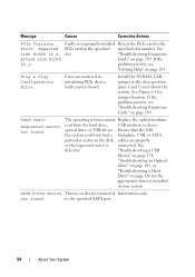
... Program and UEFI Boot Manager" on page 186. Cables to install. Use a bootable USB key, CD, or hard drive. Check the hard-drive configuration settings in System Setup program, or no bootable USB key installed. PCI BIOS failed to expansion card(s) loose;...necessary, install the operating system on hard drive. About Your System 53 See your hard drive. faulty or improperly installed expansion card(s). No timer tick interrupt. Reseat the expansion card(s). Faulty or missing optical drive subsystem, hard drive, or hard-drive subsystem, or no operating system on ...
... Program and UEFI Boot Manager" on page 186. Cables to install. Use a bootable USB key, CD, or hard drive. Check the hard-drive configuration settings in System Setup program, or no bootable USB key installed. PCI BIOS failed to expansion card(s) loose;...necessary, install the operating system on hard drive. About Your System 53 See your hard drive. faulty or improperly installed expansion card(s). No timer tick interrupt. Reseat the expansion card(s). Faulty or missing optical drive subsystem, hard drive, or hard-drive subsystem, or no operating system on ...
Hardware Owner's Manual
Page 54
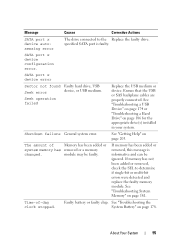
...persists, see "Troubleshooting Expansion Cards" on page 189. Plug & Play Configuration Error. The operating system cannot Replace the optical medium, read from the hard drive, USB medium or device. See Link Width is y. Install the NVRAM_CLR jumper in initializing PCIe device; SATA Portx device There is connected. Message ... in the Error: Expected PCIe card in your system. faulty system board. "Troubleshooting a USB Device" on page 174, "Troubleshooting an Optical Drive" on page 185, or "Troubleshooting a Hard Drive" on page 186 for jumper location.
...persists, see "Troubleshooting Expansion Cards" on page 189. Plug & Play Configuration Error. The operating system cannot Replace the optical medium, read from the hard drive, USB medium or device. See Link Width is y. Install the NVRAM_CLR jumper in initializing PCIe device; SATA Portx device There is connected. Message ... in the Error: Expected PCIe card in your system. faulty system board. "Troubleshooting a USB Device" on page 174, "Troubleshooting an Optical Drive" on page 185, or "Troubleshooting a Hard Drive" on page 186 for jumper location.
Hardware Owner's Manual
Page 55
Seek operation failed Replace the USB medium or device. See "Troubleshooting a USB Device" on page 174 or "Troubleshooting a Hard Drive" on page 178. The amount of -day clock stopped. About Your System 55 Shutdown failure General system error. module may be ignored. If... the faulty memory module. SATA port x device error Sector not found Faulty hard drive, USB Seek error device, or USB medium. If memory has not been added or removed, check the SEL to the Replace the faulty drive. See "Troubleshooting System Memory" on page 203. Time-of Memory has been...
Seek operation failed Replace the USB medium or device. See "Troubleshooting a USB Device" on page 174 or "Troubleshooting a Hard Drive" on page 178. The amount of -day clock stopped. About Your System 55 Shutdown failure General system error. module may be ignored. If... the faulty memory module. SATA port x device error Sector not found Faulty hard drive, USB Seek error device, or USB medium. If memory has not been added or removed, check the SEL to the Replace the faulty drive. See "Troubleshooting System Memory" on page 203. Time-of Memory has been...
Hardware Owner's Manual
Page 59
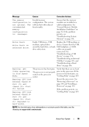
... on the processor processor has bent pins, see "Troubleshooting System Memory" on page 181. Ensure that the USB, assembly, hard drive, or hard- Faulty USB device, USB Replace the USB medium or medium, optical drive device. cables are properly connected. Message Causes Corrective Actions The memory configuration is not properly pins on the processor...
... on the processor processor has bent pins, see "Troubleshooting System Memory" on page 181. Ensure that the USB, assembly, hard drive, or hard- Faulty USB device, USB Replace the USB medium or medium, optical drive device. cables are properly connected. Message Causes Corrective Actions The memory configuration is not properly pins on the processor...
Hardware Owner's Manual
Page 69
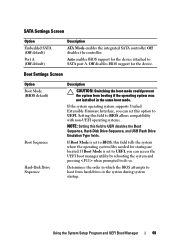
... the BIOS attempts to UEFI. Boot Settings Screen Option Boot Mode (BIOS default) Boot Sequence Hard-Disk Drive Sequence Description CAUTION: Switching the boot mode could prevent the system from hard drives in the same boot mode. If Boot Mode is set this option to boot from booting ... access the UEFI boot manager utility by rebooting the system and pressing when prompted to UEFI disables the Boot Sequence, Hard-Disk Drive Sequence, and USB Flash Drive Emulation Type fields. Using the System Setup Program and UEFI Boot Manager 69 Off disables the controller. SATA Settings Screen...
... the BIOS attempts to UEFI. Boot Settings Screen Option Boot Mode (BIOS default) Boot Sequence Hard-Disk Drive Sequence Description CAUTION: Switching the boot mode could prevent the system from hard drives in the same boot mode. If Boot Mode is set this option to boot from booting ... access the UEFI boot manager utility by rebooting the system and pressing when prompted to UEFI disables the Boot Sequence, Hard-Disk Drive Sequence, and USB Flash Drive Emulation Type fields. Using the System Setup Program and UEFI Boot Manager 69 Off disables the controller. SATA Settings Screen...
Hardware Owner's Manual
Page 70
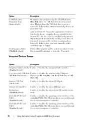
...also be accessed through the system's management controller. Floppy allows the USB flash drive to act as a hard drive. Redundancy (Disabled default) Enables or disables the internal dual SD module mirror mode. Option USB Flash Drive Emulation Type (Auto default) Boot Sequence Retry (Disabled default) Description Determines the .... If you install a device in the internal SD card slot will reattempt to boot, the system will automatically emulate a hard drive. Internal USB Port (On default) Enables or disables the internal USB port. The NICs can also be accessed through the system...
...also be accessed through the system's management controller. Floppy allows the USB flash drive to act as a hard drive. Redundancy (Disabled default) Enables or disables the internal dual SD module mirror mode. Option USB Flash Drive Emulation Type (Auto default) Boot Sequence Retry (Disabled default) Description Determines the .... If you install a device in the internal SD card slot will reattempt to boot, the system will automatically emulate a hard drive. Internal USB Port (On default) Enables or disables the internal USB port. The NICs can also be accessed through the system...
Hardware Owner's Manual
Page 86
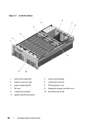
Inside the System 5 4 3 2 1 6 7 8 9 11 10 1 optical drive (optional) 3 memory risers (up to 8) 5 power supply bays (4) 7 I/O card 9 cooling fan assembly 11 system identification panel 2 control panel display 4 cooling fans (up to 6) 6 PCIe expansion card 8 integrated storage controller card 10 hard drives (up to 16) 86 Installing System Components Figure 3-1.
Inside the System 5 4 3 2 1 6 7 8 9 11 10 1 optical drive (optional) 3 memory risers (up to 8) 5 power supply bays (4) 7 I/O card 9 cooling fan assembly 11 system identification panel 2 control panel display 4 cooling fans (up to 6) 6 PCIe expansion card 8 integrated storage controller card 10 hard drives (up to 16) 86 Installing System Components Figure 3-1.


