Getting Started Guide
Page 11
Getting Started With Your System 9 SAS and SATA hard disks on the x4 backplane. x16 backplanes do not support SATA drives. Drives Hard drives Optical drive Flash drive Connectors Back NIC Serial USB Video Front Video USB Internal USB Video Video ...type Video memory Up to sixteen 2.5-inch, internal hot-swappable SAS or SSD hard drives NOTE: Only one SATA drive is supported on the same backplane cannot be combined into a single virtual disk. Optional internal SATA DVD or DVD+RW Optional external USB DVD-ROM Optional internal USB Optional internal dual...
Getting Started With Your System 9 SAS and SATA hard disks on the x4 backplane. x16 backplanes do not support SATA drives. Drives Hard drives Optical drive Flash drive Connectors Back NIC Serial USB Video Front Video USB Internal USB Video Video ...type Video memory Up to sixteen 2.5-inch, internal hot-swappable SAS or SSD hard drives NOTE: Only one SATA drive is supported on the same backplane cannot be combined into a single virtual disk. Optional internal SATA DVD or DVD+RW Optional external USB DVD-ROM Optional internal USB Optional internal dual...
Hardware Owner's Manual
Page 10
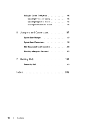
Using the Custom Test Options 195 Selecting Devices for Testing 195 Selecting Diagnostics Options 195 Viewing Information and Results 196 6 Jumpers and Connectors 197 System Board Jumper 197 System Board Connectors 198 SAS Backplane Board Connectors 200 Disabling a Forgotten Password 201 7 Getting Help 203 Contacting Dell 203 Index 205 10 Contents
Using the Custom Test Options 195 Selecting Devices for Testing 195 Selecting Diagnostics Options 195 Viewing Information and Results 196 6 Jumpers and Connectors 197 System Board Jumper 197 System Board Connectors 198 SAS Backplane Board Connectors 200 Disabling a Forgotten Password 201 7 Getting Help 203 Contacting Dell 203 Index 205 10 Contents
Hardware Owner's Manual
Page 14
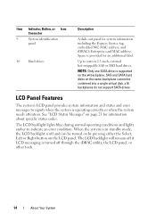
...Item Indicator, Button, or Icon Connector 9 System identification panel 10 Hard drives Description A slide-out panel for an additional label. x16 backplanes do not support SATA drives. The LCD backlight will remain off if LCD messaging is operating correctly or when the system needs attention. Space... NIC MAC address, and iDRAC6 Enterprise card MAC address. See "LCD Status Messages" on the x4 backplane. Up to indicate an error condition. SAS and SATA hard disks on the same backplane cannot be turned on by pressing either the Select, Left or Right button on the LCD panel. LCD...
...Item Indicator, Button, or Icon Connector 9 System identification panel 10 Hard drives Description A slide-out panel for an additional label. x16 backplanes do not support SATA drives. The LCD backlight will remain off if LCD messaging is operating correctly or when the system needs attention. Space... NIC MAC address, and iDRAC6 Enterprise card MAC address. See "LCD Status Messages" on the x4 backplane. Up to indicate an error condition. SAS and SATA hard disks on the same backplane cannot be turned on by pressing either the Select, Left or Right button on the LCD panel. LCD...
Hardware Owner's Manual
Page 26
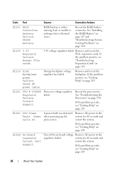
...page 203. RAID battery is either missing, bad, or unable to recharge due to the regulators failed. E1219 Disk Backplane power failure. Remove and reseat the backplane. Reseat the processor(s). E1222 CPU # VCACHE Regulator failure. See "Troubleshooting the Processors" on page 180. system ... power cable. E122C CPU Power A power fault was detected Remove AC power to the Fault. E122E On-board regulator failed. Storage backplane voltage regulator has failed. If the problem persists, see "Troubleshooting Expansion Cards" on page 203. 26 About Your System If the ...
...page 203. RAID battery is either missing, bad, or unable to recharge due to the regulators failed. E1219 Disk Backplane power failure. Remove and reseat the backplane. Reseat the processor(s). E1222 CPU # VCACHE Regulator failure. See "Troubleshooting the Processors" on page 180. system ... power cable. E122C CPU Power A power fault was detected Remove AC power to the Fault. E122E On-board regulator failed. Storage backplane voltage regulator has failed. If the problem persists, see "Troubleshooting Expansion Cards" on page 203. 26 About Your System If the ...
Hardware Owner's Manual
Page 54
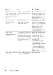
... requested sector is y. Install the NVRAM_CLR jumper in initializing PCIe device; optical drive, or USB device, Ensure that the SAS the system could not find a backplane, USB, or SATA particular sector on page 189. "Troubleshooting a USB Device" on page 174, "Troubleshooting an Optical Drive" on page 185, or "Troubleshooting a Hard Drive...
... requested sector is y. Install the NVRAM_CLR jumper in initializing PCIe device; optical drive, or USB device, Ensure that the SAS the system could not find a backplane, USB, or SATA particular sector on page 189. "Troubleshooting a USB Device" on page 174, "Troubleshooting an Optical Drive" on page 185, or "Troubleshooting a Hard Drive...
Hardware Owner's Manual
Page 55
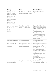
... USB medium or device. The amount of -day clock stopped. specified SATA port is informative and can be faulty. Ensure that the USB or SAS backplane cables are properly connected. Shutdown failure General system error. If memory has been added or removed, this message is faulty. See "Troubleshooting the System Battery...
... USB medium or device. The amount of -day clock stopped. specified SATA port is informative and can be faulty. Ensure that the USB or SAS backplane cables are properly connected. Shutdown failure General system error. If memory has been added or removed, this message is faulty. See "Troubleshooting the System Battery...
Hardware Owner's Manual
Page 59
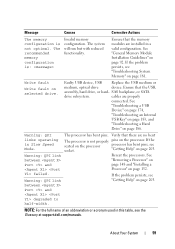
SAS backplane, or SATA drive subsystem. The processor is : Invalid memory configuration. Ensure that the USB, assembly, hard drive, or hard- Write fault Write fault on Port ...
SAS backplane, or SATA drive subsystem. The processor is : Invalid memory configuration. Ensure that the USB, assembly, hard drive, or hard- Write fault Write fault on Port ...

Hardware Owner's Manual
Page 107
... System Components 107 Doing so can take a number of hours to the system board through the SAS/SATA backplane board. Installing the Memory-Riser Guide 1 Align the memory-riser guide with the SAS/SATA backplane board. CAUTION: Before attempting to remove or install a drive while the system is running, see the documentation...
... System Components 107 Doing so can take a number of hours to the system board through the SAS/SATA backplane board. Installing the Memory-Riser Guide 1 Align the memory-riser guide with the SAS/SATA backplane board. CAUTION: Before attempting to remove or install a drive while the system is running, see the documentation...
Hardware Owner's Manual
Page 110
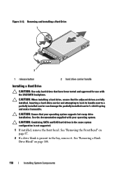
... operating system supports hot-swap drive installation. CAUTION: When installing a hard drive, ensure that your operating system. See the documentation supplied with the SAS/SATA backplane. Inserting a hard-drive carrier and attempting to lock its handle next to a partially installed carrier can damage the partially installed carrier's shield spring and make...
... operating system supports hot-swap drive installation. CAUTION: When installing a hard drive, ensure that your operating system. See the documentation supplied with the SAS/SATA backplane. Inserting a hard-drive carrier and attempting to lock its handle next to a partially installed carrier can damage the partially installed carrier's shield spring and make...

Hardware Owner's Manual
Page 111
See Figure 3-13. 3 Press the button on the front of the system. Removing a Chassis Blank 2 1 1 chassis blank 2 release tab Installing System Components 111 To remove the chassis blank, press down and push the blue release tab toward the front of the drive carrier and open the handle. 4 Insert the hard-drive carrier into the drive bay until the carrier contacts the backplane. 5 Close the handle to a 16-hard-drive configuration, turn off the system and remove all the chassis blanks. Figure 3-13. NOTE: If you are upgrading your system to lock the drive in place.
See Figure 3-13. 3 Press the button on the front of the system. Removing a Chassis Blank 2 1 1 chassis blank 2 release tab Installing System Components 111 To remove the chassis blank, press down and push the blue release tab toward the front of the drive carrier and open the handle. 4 Insert the hard-drive carrier into the drive bay until the carrier contacts the backplane. 5 Close the handle to a 16-hard-drive configuration, turn off the system and remove all the chassis blanks. Figure 3-13. NOTE: If you are upgrading your system to lock the drive in place.
Hardware Owner's Manual
Page 145
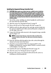
... Card CAUTION: Many repairs may only be done by its electrical outlet and turn the system on the cable. See "Removing the I/O Card" on the backplane. Read and follow the safety instructions that you connect the cable according to connector SAS B on page 134. 4 Hold the card by a certified service ... card and through the channel on the inner side of the card. 5 Connect the SAS data cable connector to servicing that is not authorized by Dell is fully seated and the plastic card guides fit over the edges of the chassis. 7 Attach the connector labeled "SAS A" to connector SAS A on ...
... Card CAUTION: Many repairs may only be done by its electrical outlet and turn the system on the cable. See "Removing the I/O Card" on the backplane. Read and follow the safety instructions that you connect the cable according to connector SAS B on page 134. 4 Hold the card by a certified service ... card and through the channel on the inner side of the card. 5 Connect the SAS data cable connector to servicing that is not authorized by Dell is fully seated and the plastic card guides fit over the edges of the chassis. 7 Attach the connector labeled "SAS A" to connector SAS A on ...
Hardware Owner's Manual
Page 159
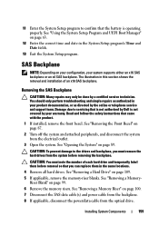
... Setup program's Time and Date fields. 13 Exit the System Setup program. Damage due to servicing that is not authorized by Dell is operating properly. CAUTION: To prevent damage to the drives and backplane, you can replace them before removal so that you must note the number of an x16 SAS...2 Turn off the system and attached peripherals, and disconnect the system from the optical drive. The illustration in your system supports either an x16 SAS backplane or an x4 SAS backplane. See "Removing the Front Bezel" on page 100. 7 Disconnect the SAS data cable(s) and power cable from the...
... Setup program's Time and Date fields. 13 Exit the System Setup program. Damage due to servicing that is not authorized by Dell is operating properly. CAUTION: To prevent damage to the drives and backplane, you can replace them before removal so that you must note the number of an x16 SAS...2 Turn off the system and attached peripherals, and disconnect the system from the optical drive. The illustration in your system supports either an x16 SAS backplane or an x4 SAS backplane. See "Removing the Front Bezel" on page 100. 7 Disconnect the SAS data cable(s) and power cable from the...
Hardware Owner's Manual
Page 160
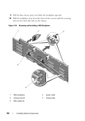
Removing and Installing a SAS Backplane 1 2 3 5 4 1 SAS backplane 3 release pins (2) 5 SAS cables (2) 2 power cable 4 chassis tabs 160 Installing System Components 9 Pull the blue release pin(s) and slide the backplane upwards. 10 Pull the backplane away from the front of the system until the securing slots are free from the tabs on the chassis. Figure 3-34.
Removing and Installing a SAS Backplane 1 2 3 5 4 1 SAS backplane 3 release pins (2) 5 SAS cables (2) 2 power cable 4 chassis tabs 160 Installing System Components 9 Pull the blue release pin(s) and slide the backplane upwards. 10 Pull the backplane away from the front of the system until the securing slots are free from the tabs on the chassis. Figure 3-34.
Hardware Owner's Manual
Page 161
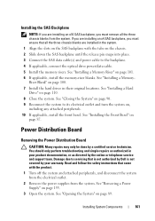
...system on, including any attached peripherals. 10 If applicable, install the front bezel. Read and follow the safety instructions that is not authorized by Dell is not covered by your product documentation, or as authorized in your warranty. See "Closing the System" on page 90. 9 Reconnect the ...repairs may only be done by the online or telephone service and support team. See "Removing a Power Supply" on page 87. Installing the SAS Backplane NOTE: If you must remove all the three chassis blanks from the system. Riser Blank" on page 110. 8 Close the system. Installing System ...
...system on, including any attached peripherals. 10 If applicable, install the front bezel. Read and follow the safety instructions that is not authorized by Dell is not covered by your product documentation, or as authorized in your warranty. See "Closing the System" on page 90. 9 Reconnect the ...repairs may only be done by the online or telephone service and support team. See "Removing a Power Supply" on page 87. Installing the SAS Backplane NOTE: If you must remove all the three chassis blanks from the system. Riser Blank" on page 110. 8 Close the system. Installing System ...
Hardware Owner's Manual
Page 188
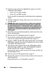
..., and turn on page 89. 7 Ensure that the controller card is properly seated. 9 Verify that the cable connections between the SAS backplane and the integrated storage controller are firmly connected to its electrical outlet. 6 Open the system. See "Installing the Integrated Storage Controller Card"...seated into the system board connector. 3 Restart the system and press the applicable key sequence to servicing that is not authorized by Dell is not covered by your product documentation, or as directed by a certified service technician. You should only perform troubleshooting and simple ...
..., and turn on page 89. 7 Ensure that the controller card is properly seated. 9 Verify that the cable connections between the SAS backplane and the integrated storage controller are firmly connected to its electrical outlet. 6 Open the system. See "Installing the Integrated Storage Controller Card"...seated into the system board connector. 3 Restart the system and press the applicable key sequence to servicing that is not authorized by Dell is not covered by your product documentation, or as directed by a certified service technician. You should only perform troubleshooting and simple ...
Hardware Owner's Manual
Page 200
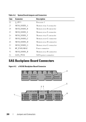
... B connector Memory riser E connector Memory riser F connector Memory riser C connector Memory riser D connector Memory riser G connector Power connector Memory riser H connector SATA power connector SAS Backplane Board Connectors Figure 6-2. Table 6-2. x16 SAS Backplane Board Connector 4 5 23 6 1 200 Jumpers and Connectors
... B connector Memory riser E connector Memory riser F connector Memory riser C connector Memory riser D connector Memory riser G connector Power connector Memory riser H connector SATA power connector SAS Backplane Board Connectors Figure 6-2. Table 6-2. x16 SAS Backplane Board Connector 4 5 23 6 1 200 Jumpers and Connectors
Hardware Owner's Manual
Page 201
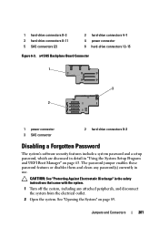
...-drive connectors 8-11 5 SAS connectors (2) 2 hard-drive connectors 4-7 4 power connector 6 hard-drive connectors 12-15 Figure 6-3. See "Opening the System" on page 63. x4 SAS Backplane Board Connector 1 3 2 1 power connector 3 SAS connector 2 hard-drive connectors 0-3 Disabling a Forgotten Password The system's software security features include a system password and a setup password, which are...
...-drive connectors 8-11 5 SAS connectors (2) 2 hard-drive connectors 4-7 4 power connector 6 hard-drive connectors 12-15 Figure 6-3. See "Opening the System" on page 63. x4 SAS Backplane Board Connector 1 3 2 1 power connector 3 SAS connector 2 hard-drive connectors 0-3 Disabling a Forgotten Password The system's software security features include a system password and a setup password, which are...
Hardware Owner's Manual
Page 206
..., 126 front bezel, 87 hard drive blank, 108 hard drives, 110 iDRAC card, 136 memory modules, 102 optical drive, 113 power supply blank, 157 SAS backplane board, 161 SAS controller, 145 H hard drive drive carrier, 112 installing, 110 removing, 109 troubleshooting, 186 heat sink, 150 hot-swap hard drives, 107 K keyboards...
..., 126 front bezel, 87 hard drive blank, 108 hard drives, 110 iDRAC card, 136 memory modules, 102 optical drive, 113 power supply blank, 157 SAS backplane board, 161 SAS controller, 145 H hard drive drive carrier, 112 installing, 110 removing, 109 troubleshooting, 186 heat sink, 150 hot-swap hard drives, 107 K keyboards...
Hardware Owner's Manual
Page 208
... 109 memory modules, 105 power supply, 155 power supply blank, 157 SAS backplane board, 159 SAS controller, 143 system board, 168 replacing power supply, 156 system battery, 157 S safety, 173 SAS backplane board installing, 161 removing, 159 SAS controller card installing, 145 removing, 143...74, 80 service-only procedure system board, 168 setup password, 81 slots See expansion slots. startup accessing system features, 11 support contacting Dell, 203 system board installing, 170 removing, 168 system cooling troubleshooting, 180 system features accessing, 11 system messages, 41 system password, ...
... 109 memory modules, 105 power supply, 155 power supply blank, 157 SAS backplane board, 159 SAS controller, 143 system board, 168 replacing power supply, 156 system battery, 157 S safety, 173 SAS backplane board installing, 161 removing, 159 SAS controller card installing, 145 removing, 143...74, 80 service-only procedure system board, 168 setup password, 81 slots See expansion slots. startup accessing system features, 11 support contacting Dell, 203 system board installing, 170 removing, 168 system cooling troubleshooting, 180 system features accessing, 11 system messages, 41 system password, ...


