
Glossary
Page 2
... an IP address to communicate with a peripheral. ECC - A method of specific processing tasks. DRAM - EMI - Electromagnetic interference. device driver - COMn - A math coprocessor, for your network server using a remote access controller. driver - See device driver. An add-in -line memory module. DC - Digital versatile disc or digital video disc. Embedded server management. See also...
... an IP address to communicate with a peripheral. ECC - A method of specific processing tasks. DRAM - EMI - Electromagnetic interference. device driver - COMn - A math coprocessor, for your network server using a remote access controller. driver - See device driver. An add-in -line memory module. DC - Digital versatile disc or digital video disc. Embedded server management. See also...
Glossary
Page 9
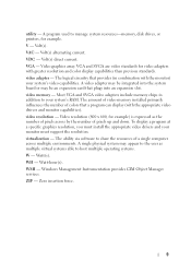
...utility - V - Volt(s) direct current. Most VGA and SVGA video adapters include memory chips in combination with the appropriate video drivers and monitor capabilities). The amount of video memory installed primarily influences the number of a single computer across by the number of ... system's RAM. VDC - The logical circuitry that a program can display (with the monitor) your monitor must install the appropriate video drivers and your system's video capabilities. WMI - VGA - To display a program at a specific graphics resolution, you must support the resolution. ...
...utility - V - Volt(s) direct current. Most VGA and SVGA video adapters include memory chips in combination with the appropriate video drivers and monitor capabilities). The amount of video memory installed primarily influences the number of a single computer across by the number of ... system's RAM. VDC - The logical circuitry that a program can display (with the monitor) your monitor must install the appropriate video drivers and your system's video capabilities. WMI - VGA - To display a program at a specific graphics resolution, you must support the resolution. ...
Information Update
Page 5
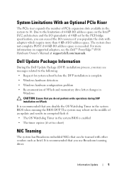
... problem • Re-enumeration of VFlash and momentary drive letter changes in Windows CAUTION: Ensure that you use Broadcom teaming driver. Dell Update Package Information During the Dell Update Package (DUP) installation process, you may reboot in the middle of an update and results in corrupted flash if:... such as Intel. For more than 4 KB of I/O address space. It is exceeded. The system may see the Dell™ PowerEdge™ R910 Hardware Owner's Manual at support.dell.com/manuals. Due to 10. The system does not complete POST if 64 KB I /O resources if you disable the...
... problem • Re-enumeration of VFlash and momentary drive letter changes in Windows CAUTION: Ensure that you use Broadcom teaming driver. Dell Update Package Information During the Dell Update Package (DUP) installation process, you may reboot in the middle of an update and results in corrupted flash if:... such as Intel. For more than 4 KB of I/O address space. It is exceeded. The system may see the Dell™ PowerEdge™ R910 Hardware Owner's Manual at support.dell.com/manuals. Due to 10. The system does not complete POST if 64 KB I /O resources if you disable the...
Hardware Owner's Manual
Page 13
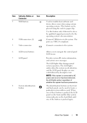
..., Button, or Icon Connector 3 NMI button 4 USB connectors (2) 5 Video connector 6 LCD menu buttons 7 LCD panel 8 System identification button Description Used to troubleshoot software and device driver errors when using certain operating systems. This button can be pressed using the end of whether the system has been powered on the back blink...
..., Button, or Icon Connector 3 NMI button 4 USB connectors (2) 5 Video connector 6 LCD menu buttons 7 LCD panel 8 System identification button Description Used to troubleshoot software and device driver errors when using certain operating systems. This button can be pressed using the end of whether the system has been powered on the back blink...
Hardware Owner's Manual
Page 21
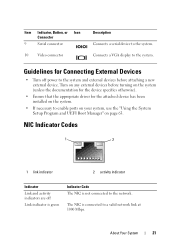
... the network. Turn on any external devices before turning on the system (unless the documentation for the device specifies otherwise). • Ensure that the appropriate driver for Connecting External Devices • Turn off Link indicator is green Indicator Code The NIC is connected to the system. The NIC is not connected...
... the network. Turn on any external devices before turning on the system (unless the documentation for the device specifies otherwise). • Ensure that the appropriate driver for Connecting External Devices • Turn off Link indicator is green Indicator Code The NIC is connected to the system. The NIC is not connected...
Hardware Owner's Manual
Page 71
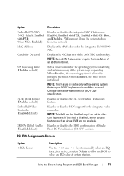
PXE support allows the system to select an IRQ value at system startup. Displays the NIC features of an additional driver. NOTE: Some LOM features may require the installation of the LOM NIC hardware key. If this field is not initialized. Other NICs: Enabled) MAC Address ...
PXE support allows the system to select an IRQ value at system startup. Displays the NIC features of an additional driver. NOTE: Some LOM features may require the installation of the LOM NIC hardware key. If this field is not initialized. Other NICs: Enabled) MAC Address ...

Hardware Owner's Manual
Page 85
Damage due to the system keylock • #1 and #2 Phillips screwdrivers • T8 and T10 Torx drivers • Wrist grounding strap Inside the System CAUTION: Many repairs may need the following items to perform the procedures in your product documentation, or as ... Tools You may only be done by a certified service technician. Installing System Components 85 Read and follow the safety instructions that is not authorized by Dell is not covered by the online or telephone service and support team.
Damage due to the system keylock • #1 and #2 Phillips screwdrivers • T8 and T10 Torx drivers • Wrist grounding strap Inside the System CAUTION: Many repairs may need the following items to perform the procedures in your product documentation, or as ... Tools You may only be done by a certified service technician. Installing System Components 85 Read and follow the safety instructions that is not authorized by Dell is not covered by the online or telephone service and support team.
Hardware Owner's Manual
Page 128
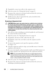
Damage due to servicing that is not authorized by Dell is not covered by your product documentation, or as directed by the online or telephone service and support team. The brackets also keep dust and ... peripherals, and disconnect the system from the card. 4 If applicable, remove the screw that came with the product. 1 Turn off the system, including any device drivers required for the card. See Figure 3-20. 6 Grasp the expansion card by a certified service technician. You should only perform troubleshooting and simple repairs as described...
Damage due to servicing that is not authorized by Dell is not covered by your product documentation, or as directed by the online or telephone service and support team. The brackets also keep dust and ... peripherals, and disconnect the system from the card. 4 If applicable, remove the screw that came with the product. 1 Turn off the system, including any device drivers required for the card. See Figure 3-20. 6 Grasp the expansion card by a certified service technician. You should only perform troubleshooting and simple repairs as described...
Hardware Owner's Manual
Page 129
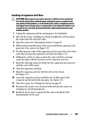
... Figure 3-22. 6 Holding the card by the online or telephone service and support team. Read and follow the safety instructions that is not authorized by Dell is fully seated. 8 Close the expansion-card latch. 9 Align the expansion-card riser with the product. 1 Unpack the expansion-card riser and prepare it for...
... Figure 3-22. 6 Holding the card by the online or telephone service and support team. Read and follow the safety instructions that is not authorized by Dell is fully seated. 8 Close the expansion-card latch. 9 Align the expansion-card riser with the product. 1 Unpack the expansion-card riser and prepare it for...
Hardware Owner's Manual
Page 164
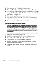
... module cable to lift the panel outward. See "Closing the System" on page 90. 5 Reconnect the system to servicing that is not authorized by Dell is not covered by the online or telephone service and support team. See "Installing the Front Bezel" on , including any attached peripherals. 6 If applicable...the control panel board. 4 Close the system. See Figure 3-36. 6 Bend the panel upward to access to the mounting screws. 7 Using a T10 Torx driver, remove the two screws that came with the product. 1 Insert the display module into the chassis cutout and secure the module with the two Torx...
... module cable to lift the panel outward. See "Closing the System" on page 90. 5 Reconnect the system to servicing that is not authorized by Dell is not covered by the online or telephone service and support team. See "Installing the Front Bezel" on , including any attached peripherals. 6 If applicable...the control panel board. 4 Close the system. See Figure 3-36. 6 Bend the panel upward to access to the mounting screws. 7 Using a T10 Torx driver, remove the two screws that came with the product. 1 Insert the display module into the chassis cutout and secure the module with the two Torx...

Hardware Owner's Manual
Page 166
... "Removing the Memory-Riser Guide" on page 99. 4 Remove the memory risers. Read and follow the safety instructions that is not authorized by Dell is not covered by your product documentation, or as you replace them to the control panel board. See "Removing a MemoryRiser Blank" on page ... with the product. 1 Turn off the system and attached peripherals, and disconnect the system from being pinched or crimped. 7 Using a T10 Torx driver, remove the three screws that secures the control panel board on the system as directed by a certified service technician. Damage due to the chassis....
... "Removing the Memory-Riser Guide" on page 99. 4 Remove the memory risers. Read and follow the safety instructions that is not authorized by Dell is not covered by your product documentation, or as you replace them to the control panel board. See "Removing a MemoryRiser Blank" on page ... with the product. 1 Turn off the system and attached peripherals, and disconnect the system from being pinched or crimped. 7 Using a T10 Torx driver, remove the three screws that secures the control panel board on the system as directed by a certified service technician. Damage due to the chassis....

Hardware Owner's Manual
Page 167
... with the product. 1 Align the screw holes on the control panel board with the holes on the chassis. 2 Using a T10 Torx driver, replace the screws that secure the control panel board to servicing that secures the control panel board on page 90. 9 Reconnect the system .... See "Installing the Memory-Riser Guide" on , including any attached peripherals. See Figure 3-36. 3 Using a T8 Torx driver, replace the screw that is not authorized by Dell is not covered by your product documentation, or as directed by a certified service technician. Installing System Components 167 See Figure 3-36...
... with the product. 1 Align the screw holes on the control panel board with the holes on the chassis. 2 Using a T10 Torx driver, replace the screws that secure the control panel board to servicing that secures the control panel board on page 90. 9 Reconnect the system .... See "Installing the Memory-Riser Guide" on , including any attached peripherals. See Figure 3-36. 3 Using a T8 Torx driver, replace the screw that is not authorized by Dell is not covered by your product documentation, or as directed by a certified service technician. Installing System Components 167 See Figure 3-36...
Hardware Owner's Manual
Page 175
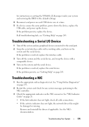
... 1 Run the appropriate online diagnostic test. If all cable connections. • If the activity indicator does not light, the network driver files might be damaged or missing. Remove and reinstall the drivers if applicable. See the NIC's documentation. If the problem is resolved, replace the interface cable. 3 Turn off the system and...
... 1 Run the appropriate online diagnostic test. If all cable connections. • If the activity indicator does not light, the network driver files might be damaged or missing. Remove and reinstall the drivers if applicable. See the NIC's documentation. If the problem is resolved, replace the interface cable. 3 Turn off the system and...
Hardware Owner's Manual
Page 176
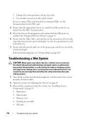
... card instead of the proper type and do not exceed the maximum length. See the documentation for the NIC card. 4 Ensure that the appropriate drivers are installed and the protocols are all network cables are of an integrated NIC, see "Getting Help" on page 89. 3 Disassemble components from... Open the system. If you are enabled. See the NIC's documentation. 5 Enter the System Setup program and confirm that is not authorized by Dell is not covered by your product documentation, or as authorized in your warranty. Troubleshooting a Wet System CAUTION: Many repairs may only be done by...
... card instead of the proper type and do not exceed the maximum length. See the documentation for the NIC card. 4 Ensure that the appropriate drivers are installed and the protocols are all network cables are of an integrated NIC, see "Getting Help" on page 89. 3 Disassemble components from... Open the system. If you are enabled. See the NIC's documentation. 5 Enter the System Setup program and confirm that is not authorized by Dell is not covered by your product documentation, or as authorized in your warranty. Troubleshooting a Wet System CAUTION: Many repairs may only be done by...
Hardware Owner's Manual
Page 186
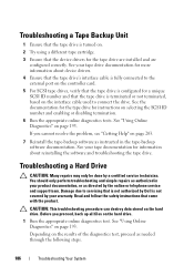
...ID number and that the tape drive is terminated or not terminated, based on the interface cable used to servicing that is not authorized by Dell is turned on. 2 Try using a different tape cartridge. 3 Ensure that came with the product. Troubleshooting a Tape Backup Unit 1 Ensure... steps. 186 Troubleshooting Your System You should only perform troubleshooting and simple repairs as instructed in your tape documentation for information about device drivers. 4 Ensure that the tape drive's interface cable is fully connected to the external port on the controller card. 5 For SCSI tape...
...ID number and that the tape drive is terminated or not terminated, based on the interface cable used to servicing that is not authorized by Dell is turned on. 2 Try using a different tape cartridge. 3 Ensure that came with the product. Troubleshooting a Tape Backup Unit 1 Ensure... steps. 186 Troubleshooting Your System You should only perform troubleshooting and simple repairs as instructed in your tape documentation for information about device drivers. 4 Ensure that the tape drive's interface cable is fully connected to the external port on the controller card. 5 For SCSI tape...
Hardware Owner's Manual
Page 187
... enabled. If the problem persists, see the documentation for more information. 5 Restart the system, enter the System Setup program, and verify that the required device drivers for information about the configuration utility. Troubleshooting Your System 187 See the documentation supplied with the host adapter for your controller card are installed and...
... enabled. If the problem persists, see the documentation for more information. 5 Restart the system, enter the System Setup program, and verify that the required device drivers for information about the configuration utility. Troubleshooting Your System 187 See the documentation supplied with the host adapter for your controller card are installed and...


