Service Manual
Page 3
... In addition to the standard features found in a traditional personal computer, Dell PowerEdge 4100 systems include the following new and/or advanced features: • 256 KB (PowerEdge 4100/180 systems) or 512 KB (PowerEdge 4100/200 systems) of cache memory internal to a multiple of microprocessors. The PowerEdge 4100 systems are installed in zero insertion force (ZIF) sockets on the system...
... In addition to the standard features found in a traditional personal computer, Dell PowerEdge 4100 systems include the following new and/or advanced features: • 256 KB (PowerEdge 4100/180 systems) or 512 KB (PowerEdge 4100/200 systems) of cache memory internal to a multiple of microprocessors. The PowerEdge 4100 systems are installed in zero insertion force (ZIF) sockets on the system...

Service Manual
Page 4
...slots (none shared) • Integrated VGA-compatible video subsystem attached to the PCI bus, with 1 MB video memory standard • BIOS in upgradable flash memory attached to the EISA bus • Integrated super I/O controller attached to prevent accidental system interruptions • New...system volt- ages and temperatures, as well as the operation of system features, see the "Dell PowerEdge 4100 and 6100 Systems Rack Kit Installation Guide" (P/N 40722). 1-2 Dell PowerEdge 4100/180 and 4100/200 Systems Service Manual For information about the Quick Test option in the CD-ROM based ...
...slots (none shared) • Integrated VGA-compatible video subsystem attached to the PCI bus, with 1 MB video memory standard • BIOS in upgradable flash memory attached to the EISA bus • Integrated super I/O controller attached to prevent accidental system interruptions • New...system volt- ages and temperatures, as well as the operation of system features, see the "Dell PowerEdge 4100 and 6100 Systems Rack Kit Installation Guide" (P/N 40722). 1-2 Dell PowerEdge 4100/180 and 4100/200 Systems Service Manual For information about the Quick Test option in the CD-ROM based ...
Service Manual
Page 10
..., EDO dual in conjunction with the Intel LANDesk® Server Management suite. 1-8 Dell PowerEdge 4100/180 and 4100/200 Systems Service Manual The socket population rules for the DIMMs are located on the system board. The ECC feature provides more reliable memory and less downtime, and is rebooted. The eight expansion-card slots include three...
..., EDO dual in conjunction with the Intel LANDesk® Server Management suite. 1-8 Dell PowerEdge 4100/180 and 4100/200 Systems Service Manual The socket population rules for the DIMMs are located on the system board. The ECC feature provides more reliable memory and less downtime, and is rebooted. The eight expansion-card slots include three...
Service Manual
Page 11
...colors. Maximum noninterlaced resolutions are not supported by the built-in the other devices, their configuration requirements are different. In the standard Dell PowerEdge 4100 system configuration, the Ultra/Wide SCSI host adapter on the system board. A built-in Adaptec 7860 Ultra/Narrow SCSI controller provides a...connector on the system board controls the SCSI backplane board. NOTES: The externally accessible drive bays at the front of DRAM memory (the video memory size is connected to 1.6-inch-high SCSI hard-disk drives (either fast/wide or ultra [fast] wide). For detailed ...
...colors. Maximum noninterlaced resolutions are not supported by the built-in the other devices, their configuration requirements are different. In the standard Dell PowerEdge 4100 system configuration, the Ultra/Wide SCSI host adapter on the system board. A built-in Adaptec 7860 Ultra/Narrow SCSI controller provides a...connector on the system board controls the SCSI backplane board. NOTES: The externally accessible drive bays at the front of DRAM memory (the video memory size is connected to 1.6-inch-high SCSI hard-disk drives (either fast/wide or ultra [fast] wide). For detailed ...

Service Manual
Page 17
...speaker System Overview 1-15 system board keyboard controller power management logic PWRGOOD PSON# +5 VFP +5 VDC -5 VDC +12 VDC -12 VDC +3.3 VDC main memory sockets DIMM A through DIMM H +3.3 VDC RTC/ NVRAM battery +3.3 VDC +5 VDC +12 VDC -12 VDC PCI4 through PCI8 +5 VDC -5 VDC +...VCC (+2.1 to the control panel. DC Power Distribution (Nonredundant System) Figures 1-11 provides information about DC power distribution for the nonredundant PowerEdge 4100 system. The control panel cable (30-pin) carries the +5 VFP from the backplane to +3.5 VDC) PROCESSOR1 and PROCESSOR2 +1.5 VDC ...
...speaker System Overview 1-15 system board keyboard controller power management logic PWRGOOD PSON# +5 VFP +5 VDC -5 VDC +12 VDC -12 VDC +3.3 VDC main memory sockets DIMM A through DIMM H +3.3 VDC RTC/ NVRAM battery +3.3 VDC +5 VDC +12 VDC -12 VDC PCI4 through PCI8 +5 VDC -5 VDC +...VCC (+2.1 to the control panel. DC Power Distribution (Nonredundant System) Figures 1-11 provides information about DC power distribution for the nonredundant PowerEdge 4100 system. The control panel cable (30-pin) carries the +5 VFP from the backplane to +3.5 VDC) PROCESSOR1 and PROCESSOR2 +1.5 VDC ...
Service Manual
Page 21
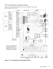
... +5 VDC PWRFD (FD1-4) +12 VDC +5 VDC system board keyboard controller power management logic BATV PWRGOOD PSON# +5 VFP +5 VDC -5 VDC +12 VDC -12 VDC +3.3 VDC main memory sockets DIMM A through DIMM H +3.3 VDC RTC/ NVRAM battery +3.3 VDC +5 VDC +12 VDC -12 VDC PCI4 through PCI8 +5 VDC -5 VDC +12 VDC -12 VDC battery (+3 VDC... on/off power-on LED speaker System Overview 1-19 DC Power Distribution (Redundant System) Figures 1-17 provides information about DC power distribution for the redundant PowerEdge 4100 system.
... +5 VDC PWRFD (FD1-4) +12 VDC +5 VDC system board keyboard controller power management logic BATV PWRGOOD PSON# +5 VFP +5 VDC -5 VDC +12 VDC -12 VDC +3.3 VDC main memory sockets DIMM A through DIMM H +3.3 VDC RTC/ NVRAM battery +3.3 VDC +5 VDC +12 VDC -12 VDC PCI4 through PCI8 +5 VDC -5 VDC +12 VDC -12 VDC battery (+3 VDC... on/off power-on LED speaker System Overview 1-19 DC Power Distribution (Redundant System) Figures 1-17 provides information about DC power distribution for the redundant PowerEdge 4100 system.
Service Manual
Page 23
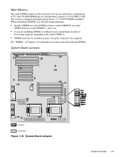
and 128-MB DIMMs up to a total memory capacity of decreasing capacity, beginning with high-speed (60-ns) 3.3-V EDO DIMMs installed. The system is shipped with socket DIMM A. • DIMMs need not be ... System Overview 1-21 See "DIMMs" in pairs, but gold connectors are installing DIMMs of different sizes, install them in order of 1024 MB (1 GB). Main Memory The eight DIMM sockets on removing and replacing DIMMs. System Board Jumpers jumpered unjumpered Figure 1-19.
and 128-MB DIMMs up to a total memory capacity of decreasing capacity, beginning with high-speed (60-ns) 3.3-V EDO DIMMs installed. The system is shipped with socket DIMM A. • DIMMs need not be ... System Overview 1-21 See "DIMMs" in pairs, but gold connectors are installing DIMMs of different sizes, install them in order of 1024 MB (1 GB). Main Memory The eight DIMM sockets on removing and replacing DIMMs. System Board Jumpers jumpered unjumpered Figure 1-19.
Service Manual
Page 27
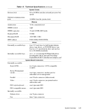
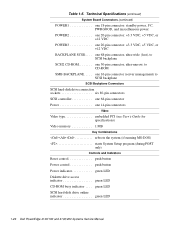
to 1.6-inch-high SCSI hard-disk drives, hot-pluggable with an optional PowerEdge Expandable RAID Controller host adapter card System Board Connectors Externally accessible: Serial (DTE two 9-pin connectors; 16550-compatible (UART) Server Management (serial one 34...Technical Specifications (continued) System Clocks System clock 60 or 66 MHz (matches external processor bus speed) Diskette/communications ports 24 MHz from the system clock Memory Architecture 72-bit, noninterleaved DIMM sockets eight DIMM capacities 32 and 128 MB, EDO mode Standard RAM 64 MB Maximum RAM 1024 MB (1 GB) BIOS...
to 1.6-inch-high SCSI hard-disk drives, hot-pluggable with an optional PowerEdge Expandable RAID Controller host adapter card System Board Connectors Externally accessible: Serial (DTE two 9-pin connectors; 16550-compatible (UART) Server Management (serial one 34...Technical Specifications (continued) System Clocks System clock 60 or 66 MHz (matches external processor bus speed) Diskette/communications ports 24 MHz from the system clock Memory Architecture 72-bit, noninterleaved DIMM sockets eight DIMM capacities 32 and 128 MB, EDO mode Standard RAM 64 MB Maximum RAM 1024 MB (1 GB) BIOS...
Service Manual
Page 28
... 80-pin connectors SCSI controller one 68-pin connector Power one 14-pin connectors Video Video type embedded PCI (see User's Guide for specifications) Video memory 1 MB Key Combinations one 16-pin connector (server management) to SCSI backplane SCSI2 CD-ROM one 20-pin connector: +3.3 VDC, +5 VDC, or +12 VDC BACKPLANE...
... 80-pin connectors SCSI controller one 68-pin connector Power one 14-pin connectors Video Video type embedded PCI (see User's Guide for specifications) Video memory 1 MB Key Combinations one 16-pin connector (server management) to SCSI backplane SCSI2 CD-ROM one 20-pin connector: +3.3 VDC, +5 VDC, or +12 VDC BACKPLANE...

Service Manual
Page 33
... the power supply fans. No. After all three indicators flash momentarily, and following : • Beep codes: A beep code is operational, troubleshoot the memory. 4. If the system emits a beep code, see Table 3-2. • Diskette-drive and hard-disk drive activity indicators: These indicators light up during the... supply. Yes. It may be necessary to reboot the system several times in response to data being transferred to step 4. Insert the Dell Server Assistant CD into the CD-ROM drive. Press the reset button or to step 3. NOTE: The center fan is too high....
... the power supply fans. No. After all three indicators flash momentarily, and following : • Beep codes: A beep code is operational, troubleshoot the memory. 4. If the system emits a beep code, see Table 3-2. • Diskette-drive and hard-disk drive activity indicators: These indicators light up during the... supply. Yes. It may be necessary to reboot the system several times in response to data being transferred to step 4. Insert the Dell Server Assistant CD into the CD-ROM drive. Press the reset button or to step 3. NOTE: The center fan is too high....

Service Manual
Page 35
...the system to be allocated during installation of main memory (RAM) required for loading the diagnostics. Because a device may require dedicated memory spaces, interrupt levels, or DMA channels, all . Restarting the computer causes the Dell Server Assistant logo screen to their power sources, ...to the next section, "Eliminating Resource Conflicts," and to their appropriate connectors. 6. If a main memory error is possible that they are firmly attached to appear on the Dell Server Assistant CD) contains tests that aid in disorderly or erratic system operation or failure of which...
...the system to be allocated during installation of main memory (RAM) required for loading the diagnostics. Because a device may require dedicated memory spaces, interrupt levels, or DMA channels, all . Restarting the computer causes the Dell Server Assistant logo screen to their power sources, ...to the next section, "Eliminating Resource Conflicts," and to their appropriate connectors. 6. If a main memory error is possible that they are firmly attached to appear on the Dell Server Assistant CD) contains tests that aid in disorderly or erratic system operation or failure of which...
Service Manual
Page 36
For instructions, see Chapter 11, "Getting Help," in main memory, and the Dell Server Assistant loads, select the Run System Utilities icon. Runs selected tests from all tests for technical assistance. Tests a particular area or subsystem ...; Run Quick Tests - Then select the Run System Diagnostics icon by pressing . If no errors are found in the Installation and Troubleshooting Guide. 2-6 Dell PowerEdge 4100/180 and 4100/200 Systems Service Manual The Diagnostics Menu appears, allowing you to choose the following options or exit to isolate a failure • Run Specific Tests...
For instructions, see Chapter 11, "Getting Help," in main memory, and the Dell Server Assistant loads, select the Run System Utilities icon. Runs selected tests from all tests for technical assistance. Tests a particular area or subsystem ...; Run Quick Tests - Then select the Run System Diagnostics icon by pressing . If no errors are found in the Installation and Troubleshooting Guide. 2-6 Dell PowerEdge 4100/180 and 4100/200 Systems Service Manual The Diagnostics Menu appears, allowing you to choose the following options or exit to isolate a failure • Run Specific Tests...
Service Manual
Page 38
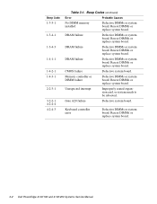
... board. DRAM failure Defective DIMMs or system board. Keyboard controller error Defective DIMMs or system board. Reseat DIMMs or replace system board. 3-2 Dell PowerEdge 4100/180 and 4100/200 Systems Service Manual Memory controller or DIMM failure Defective DIMMs or system board. Reseat DIMMs or replace system board. Gate A20 failure Defective system board. DRAM...
... board. DRAM failure Defective DIMMs or system board. Keyboard controller error Defective DIMMs or system board. Reseat DIMMs or replace system board. 3-2 Dell PowerEdge 4100/180 and 4100/200 Systems Service Manual Memory controller or DIMM failure Defective DIMMs or system board. Reseat DIMMs or replace system board. Gate A20 failure Defective system board. DRAM...
Service Manual
Page 40
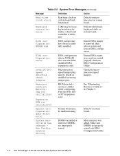
...jumpers. More memory was added or removed. System Error Messages (continued) Message Definition Action Real-time clock error Real-time clock on wrong jumper pins. Defective microprocessor or system board. Ensure EISA jumper is defective. then run EISA Configuration Utility. 3-4 Dell PowerEdge 4100/180 and 4100/200 Systems ...EISA configuration error EISA configuration data in Chapter 2. Table 3-2. EISA configuration NVRAM bad EISA jumper may be malfunctioning. System memory size has changed Run Configuration Utility DIMM was added. DIMMs are improperly seated.
...jumpers. More memory was added or removed. System Error Messages (continued) Message Definition Action Real-time clock error Real-time clock on wrong jumper pins. Defective microprocessor or system board. Ensure EISA jumper is defective. then run EISA Configuration Utility. 3-4 Dell PowerEdge 4100/180 and 4100/200 Systems ...EISA configuration error EISA configuration data in Chapter 2. Table 3-2. EISA configuration NVRAM bad EISA jumper may be malfunctioning. System memory size has changed Run Configuration Utility DIMM was added. DIMMs are improperly seated.

Service Manual
Page 41
Wrong microprocessor installed in PROCESSOR1 socket. System halted. Cache memory sizes of CPU1 is less than sA1 System halted. Check microprocessor speed jumpers. Check servermanagement bus cable ... or greater. Nonidentical CPUs - Wrong microprocessor installed in system. Check speed jumpers. Embedded server management firmware download failed Embedded server management memory temporarily corrupted. Table 3-2. Invalid CPU speed detected - Power supply paralleling board firmware download failed System backplane firmware download failed Server-management ...
Wrong microprocessor installed in PROCESSOR1 socket. System halted. Cache memory sizes of CPU1 is less than sA1 System halted. Check microprocessor speed jumpers. Check servermanagement bus cable ... or greater. Nonidentical CPUs - Wrong microprocessor installed in system. Check speed jumpers. Embedded server management firmware download failed Embedded server management memory temporarily corrupted. Table 3-2. Invalid CPU speed detected - Power supply paralleling board firmware download failed System backplane firmware download failed Server-management ...
Service Manual
Page 67
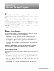
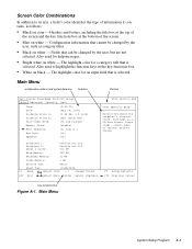
then shut down the system and try again. and rightarrow keys to load into memory and you cannot enter the System Setup program. Lists configuration categories (left of the selection. System Setup Screens The System Setup program is cur- To ...
then shut down the system and try again. and rightarrow keys to load into memory and you cannot enter the System Setup program. Lists configuration categories (left of the selection. System Setup Screens The System Setup program is cur- To ...
Service Manual
Page 69
... , , or selects fields Processor 1: Processor 2: Level 2 Cache: Pentium Pro 200 Pentium Pro 200 512 KB Base Memory: 640 KB Extended Memory: 63 MB Video Memory: 1 MB Service Tag: AB12Z Asset Tag: 123456789A F1 Help Select Item -/+ Change Values ESC Exit Select Menu Enter Select...white - Main Menu configuration options and system data box help messages. • Bright white on cyan - Also used for help box title box Dell System PowerEdge 4100/200 Setup Main Advanced Security Exit Time: [5:01:96] Date: [May 04, 1996] Diskette Drive A: [1.44 MB, 3.5 inch] Diskette...
... , , or selects fields Processor 1: Processor 2: Level 2 Cache: Pentium Pro 200 Pentium Pro 200 512 KB Base Memory: 640 KB Extended Memory: 63 MB Video Memory: 1 MB Service Tag: AB12Z Asset Tag: 123456789A F1 Help Select Item -/+ Change Values ESC Exit Select Menu Enter Select...white - Main Menu configuration options and system data box help messages. • Bright white on cyan - Also used for help box title box Dell System PowerEdge 4100/200 Setup Main Advanced Security Exit Time: [5:01:96] Date: [May 04, 1996] Diskette Drive A: [1.44 MB, 3.5 inch] Diskette...
Service Manual
Page 70
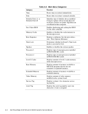
... up to MS-DOS programs that do not use extended or expanded memory. Category options always match physical locations of memory available as extended memory. Video Memory Displays amount of memory available to ten characters, if one is activated at boot. Service ... shadowing and caching the BIOS for the video controller. Memory Cache Enables or disables the cache memory in these categories. Extended Memory Displays amount of drives in PROCESSOR1 socket. A-4 Dell PowerEdge 4100/180 and 4100/200 Systems Service Manual Num Lock Determines whether keyboard's ...
... up to MS-DOS programs that do not use extended or expanded memory. Category options always match physical locations of memory available as extended memory. Video Memory Displays amount of memory available to ten characters, if one is activated at boot. Service ... shadowing and caching the BIOS for the video controller. Memory Cache Enables or disables the cache memory in these categories. Extended Memory Displays amount of drives in PROCESSOR1 socket. A-4 Dell PowerEdge 4100/180 and 4100/200 Systems Service Manual Num Lock Determines whether keyboard's ...
Service Manual
Page 81
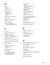
See hard-disk drives, SCSI SCSI ID numbers, 1-10 SERIAL connectors, 4-17 Index 3 M memory main, 1-21 system, 1-8 messages, error, 3-3 microprocessor release lever, 4-21 removal, 4-20, 4-21 sockets, 4-17 microprocessor cooling fans removal, 4-16 MONITOR connector, 4-17 MOUSE connector, 4-17 ...
See hard-disk drives, SCSI SCSI ID numbers, 1-10 SERIAL connectors, 4-17 Index 3 M memory main, 1-21 system, 1-8 messages, error, 3-3 microprocessor release lever, 4-21 removal, 4-20, 4-21 sockets, 4-17 microprocessor cooling fans removal, 4-16 MONITOR connector, 4-17 MOUSE connector, 4-17 ...
Service Manual
Page 82
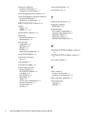
... 1-7 location on system board, 4-17 SMB BACKPLANE connector, 4-17 sockets battery, 4-23 DIMM, 4-17, 4-19 specifications, technical, 1-24 subsystems advanced expansion, 1-8 main memory, 1-21 system board components, 4-17 illustrated, 1-20 jumpers, 1-21 location, 1-5 removing and replacing, 4-24 system board jumpers, 1-21 system error messages list of, ... user contact, initial, 2-1 V video connector location on I/O panel, 1-7 location on system board, 4-17 video controller, integrated, 1-9 visual inspection external, 2-2 internal, 2-4 4 Dell PowerEdge 4100/180 and 4100/200 Systems Service Manual
... 1-7 location on system board, 4-17 SMB BACKPLANE connector, 4-17 sockets battery, 4-23 DIMM, 4-17, 4-19 specifications, technical, 1-24 subsystems advanced expansion, 1-8 main memory, 1-21 system board components, 4-17 illustrated, 1-20 jumpers, 1-21 location, 1-5 removing and replacing, 4-24 system board jumpers, 1-21 system error messages list of, ... user contact, initial, 2-1 V video connector location on I/O panel, 1-7 location on system board, 4-17 video controller, integrated, 1-9 visual inspection external, 2-2 internal, 2-4 4 Dell PowerEdge 4100/180 and 4100/200 Systems Service Manual


