Installing the S25P System
Page 7
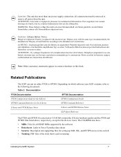
... if battery is replaced with the same type recommended by the software • Data sheets: Links to the switch • Training: PDF files of used in training Installing the S25P System 7 Il y a danger d'explosion s'il a remplacement incorrect de la batterie. Remplacer uniquement avec une batterie du meme type ou d'un type equivalent recommande par le constructeur. Caution: This unit has more than one power supply connection; Replace only...
... if battery is replaced with the same type recommended by the software • Data sheets: Links to the switch • Training: PDF files of used in training Installing the S25P System 7 Il y a danger d'explosion s'il a remplacement incorrect de la batterie. Remplacer uniquement avec une batterie du meme type ou d'un type equivalent recommande par le constructeur. Caution: This unit has more than one power supply connection; Replace only...
Installing the S25P System
Page 9
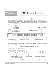
..., facing rear) Ground Connector Dual AC Power Receptacles Note: For the back panel of the XFP ports in two expansion slots. For stacking details, see Figure 4 on page 15 and Supplying Power on page 27. Chapter 1 S25P System Overview The Force10 Networks S25P (Cat# S25-01-GE-24P) is a high performance, low cost, stackable, Layer 2 switch/Layer 3 router that displays activity of the S25P-DC, see Connecting Stack Ports...
..., facing rear) Ground Connector Dual AC Power Receptacles Note: For the back panel of the XFP ports in two expansion slots. For stacking details, see Figure 4 on page 15 and Supplying Power on page 27. Chapter 1 S25P System Overview The Force10 Networks S25P (Cat# S25-01-GE-24P) is a high performance, low cost, stackable, Layer 2 switch/Layer 3 router that displays activity of the S25P-DC, see Connecting Stack Ports...

Installing the S25P System
Page 10
...; Stacking cables for connecting S-Series switches in a stack • Optical networking components (see Chapter 4, Installing Ports, on page 29) • Stacking components (see Ports, below) Features • S25P CPU and switch processor • 32MB internal Flash memory • 256MB RAM • Stackable switch features • 19-inch rack-mountable • Standard 1U chassis height • Six built-in fans • Two internal AC power supplies acting in load-sharing mode •...
...; Stacking cables for connecting S-Series switches in a stack • Optical networking components (see Chapter 4, Installing Ports, on page 29) • Stacking components (see Ports, below) Features • S25P CPU and switch processor • 32MB internal Flash memory • 256MB RAM • Stackable switch features • 19-inch rack-mountable • Standard 1U chassis height • Six built-in fans • Two internal AC power supplies acting in load-sharing mode •...
Installing the S25P System
Page 11
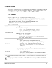
... software (FTOS or SFTOS). Blinking Green - Link up on this port Blinking Green - A valid 1000Mbps link is enabled. Amber - LED Displays As shown in the Status Display at this port. Link up , 100Mbps state. Link/Active LED (right side of the front panel labeled "STACK ID". Installing the S25P System 11 No link detected at this port. For details on those options, see Stacking on page 24. • Status indicator LEDs on the module...
... software (FTOS or SFTOS). Blinking Green - Link up on this port Blinking Green - A valid 1000Mbps link is enabled. Amber - LED Displays As shown in the Status Display at this port. Link up , 100Mbps state. Link/Active LED (right side of the front panel labeled "STACK ID". Installing the S25P System 11 No link detected at this port. For details on those options, see Stacking on page 24. • Status indicator LEDs on the module...
Installing the S25P System
Page 14
... ambient temperature ranges are operating normally, including fans. As listed in Table 4, "Status Panel LED Display," on page 12, the front panel of clearance around the side intake and exhaust vents. In a stack, each unit has its own temperature monitoring and control. For details, see the log messages. When two S25P systems are installed side by side, position the two S25P chassis at a constant speed. The Command Line Interface...
... ambient temperature ranges are operating normally, including fans. As listed in Table 4, "Status Panel LED Display," on page 12, the front panel of clearance around the side intake and exhaust vents. In a stack, each unit has its own temperature monitoring and control. For details, see the log messages. When two S25P systems are installed side by side, position the two S25P chassis at a constant speed. The Command Line Interface...
Installing the S25P System
Page 17
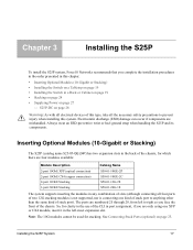
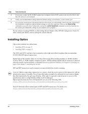
... and its components. Installing the S25P System 17 Inserting Optional Modules (10-Gigabit or Stacking) The S25P (catalog name S25-01-GE-24P) has two expansion slots in the back of the chassis, for which there are only using one kind of stack port to right as you face the front of the chassis. So, for stacking. See Connecting Stack Ports (optional) on page...
... and its components. Installing the S25P System 17 Inserting Optional Modules (10-Gigabit or Stacking) The S25P (catalog name S25-01-GE-24P) has two expansion slots in the back of the chassis, for which there are only using one kind of stack port to right as you face the front of the chassis. So, for stacking. See Connecting Stack Ports (optional) on page...
Installing the S25P System
Page 19
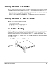
... the chassis in a Rack or Cabinet The S25P provides three rack-mounting methods: • Two-Post Rack Mounting • Four-Post Rack-mounting with Threaded Rails • Four-Post Rack-mounting with Cage Nuts Two-Post Rack Mounting The S25P is shipped with the universal front-mounting brackets (rack ears) attached. Installing the Switch on a stable tabletop. Figure 6 S25P Two-post (Front-mounted) Rack-mounting Stack ID AC1 XFP25 XFP26 AACla2rm 27 P28 S25-01-GE-24P Installing the S25P...
... the chassis in a Rack or Cabinet The S25P provides three rack-mounting methods: • Two-Post Rack Mounting • Four-Post Rack-mounting with Threaded Rails • Four-Post Rack-mounting with Cage Nuts Two-Post Rack Mounting The S25P is shipped with the universal front-mounting brackets (rack ears) attached. Installing the Switch on a stable tabletop. Figure 6 S25P Two-post (Front-mounted) Rack-mounting Stack ID AC1 XFP25 XFP26 AACla2rm 27 P28 S25-01-GE-24P Installing the S25P...
Installing the S25P System
Page 20
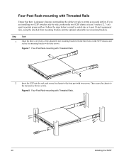
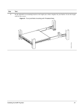
... S25-01-GE-24P 2 Insert the S25P into a 4-post 19-inch equipment rack, using the attached front mounting brackets and the optional adjustable rear-mounting brackets. Follow the steps below to install a switch into the rack, and secure the chassis to the rear posts with three screws. Figure 8 Four-Post Rack-mounting with Threaded Rails Ensure that there is adequate clearance surrounding the cabinet or rack to permit proper airflow. Four-Post Rack-mounting...
... S25-01-GE-24P 2 Insert the S25P into a 4-post 19-inch equipment rack, using the attached front mounting brackets and the optional adjustable rear-mounting brackets. Follow the steps below to install a switch into the rack, and secure the chassis to the rear posts with three screws. Figure 8 Four-Post Rack-mounting with Threaded Rails Ensure that there is adequate clearance surrounding the cabinet or rack to permit proper airflow. Four-Post Rack-mounting...
Installing the S25P System
Page 21
Stack ID AC1 XFP25 XFP26 AACla2rm 27 P28 S25-01-GE-24P fn00146cs25P.eps Installing the S25P System 21 Secure the length with Threaded Rails . Figure 9 Four-post Rack-mounting with the four screws. Step 3 Task Set the adjustable rear mounting bracket to the length (one of three lengths) for your bracket.
Stack ID AC1 XFP25 XFP26 AACla2rm 27 P28 S25-01-GE-24P fn00146cs25P.eps Installing the S25P System 21 Secure the length with Threaded Rails . Figure 9 Four-post Rack-mounting with the four screws. Step 3 Task Set the adjustable rear mounting bracket to the length (one of three lengths) for your bracket.
Installing the S25P System
Page 24
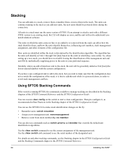
... numbers, stack management assignment, and other stacking commands, see the Stacking chapter in the SFTOS Configuration Guide and the Stacking Commands chapter in which the units come online. Then pre-configure it is powered down during the connection. You can use commands such as you add new units, but new units should have a pre-configured unit to add to the stack, but you install identical software...
... numbers, stack management assignment, and other stacking commands, see the Stacking chapter in the SFTOS Configuration Guide and the Stacking Commands chapter in which the units come online. Then pre-configure it is powered down during the connection. You can use commands such as you add new units, but new units should have a pre-configured unit to add to the stack, but you install identical software...
Installing the S25P System
Page 28
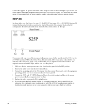
... Installing the S25P name S25-01-GE-24P-DC) has two DC terminal blocks on the left side (as you face the rear of the chassis) and then to the power source (see also Figure 4 on the DC terminal blocks. 6 If you are connecting both terminal blocks, do not supply power until both terminal blocks are connected. The S25P-DC uses the power supplies in...
... Installing the S25P name S25-01-GE-24P-DC) has two DC terminal blocks on the left side (as you face the rear of the chassis) and then to the power source (see also Figure 4 on the DC terminal blocks. 6 If you are connecting both terminal blocks, do not supply power until both terminal blocks are connected. The S25P-DC uses the power supplies in...
Installing the S25P System
Page 30
... or removed when the switch is powered down, as detailed in Inserting Optional Modules (10-Gigabit or Stacking) on the console port: 4 If you use the console port to download software to the switch, you will probably want to raise the console baud rate. Caution: Before connecting a transceiver to a source, check the receive power of the transceiver with the default settings to verify the connection. Optical specifications for other console port details...
... or removed when the switch is powered down, as detailed in Inserting Optional Modules (10-Gigabit or Stacking) on the console port: 4 If you use the console port to download software to the switch, you will probably want to raise the console baud rate. Caution: Before connecting a transceiver to a source, check the receive power of the transceiver with the default settings to verify the connection. Optical specifications for other console port details...
Installing the S25P System
Page 31
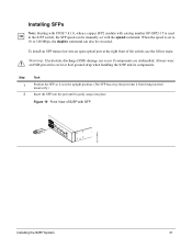
... catalog number GP-SFP2-1T is used in the upright position. (The SFP has a key that prevents it from being inserted incorrectly.) Insert the SFP into the port until it gently snaps into an open optical port at the right front of S25P with the speed command. Step 1 2 Task Position the SFP so it is set with SFP S25-01-GE-24P fn00161s25P Installing...
... catalog number GP-SFP2-1T is used in the upright position. (The SFP has a key that prevents it from being inserted incorrectly.) Insert the SFP into the port until it gently snaps into an open optical port at the right front of S25P with the speed command. Step 1 2 Task Position the SFP so it is set with SFP S25-01-GE-24P fn00161s25P Installing...
Installing the S25P System
Page 32
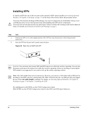
... up the switch, requiring a reboot. XFP-1CX4) into any optical port. With SFTOS, see Information Symbols and Warnings on page 17 in physical harm. Note: The CX4 module does not use of the cx4-cable-length command. For details, see the FTOS Configuration Guide. Warning: Do not look directly into the slot. Step 1 2 Task Position the XFP so it can use a CX4 cable with FTOS...
... up the switch, requiring a reboot. XFP-1CX4) into any optical port. With SFTOS, see Information Symbols and Warnings on page 17 in physical harm. Note: The CX4 module does not use of the cx4-cable-length command. For details, see the FTOS Configuration Guide. Warning: Do not look directly into the slot. Step 1 2 Task Position the XFP so it can use a CX4 cable with FTOS...
Installing the S25P System
Page 41
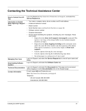
... contact • Model number • Serial Number (see Locating Serial Numbers on the iSupport page. E-mail: support@force10networks.com Web: http://www.force10networks.com/support/ Telephone: US and Canada: 866.965.5800 International: 408.965.5800 Installing the S25P System 41 Contacting the Technical Assistance Center How to Contact Force10 TAC Information to Submit When Opening a Support Case Managing Your Case Downloading Software Updates Technical Documentation Contact Information Log in to iSupport...
... contact • Model number • Serial Number (see Locating Serial Numbers on the iSupport page. E-mail: support@force10networks.com Web: http://www.force10networks.com/support/ Telephone: US and Canada: 866.965.5800 International: 408.965.5800 Installing the S25P System 41 Contacting the Technical Assistance Center How to Contact Force10 TAC Information to Submit When Opening a Support Case Managing Your Case Downloading Software Updates Technical Documentation Contact Information Log in to iSupport...
Installing the S25P System
Page 45
... Power Supply 6 AC1 9 AC2 9 acoustic noise 33 add units to a stack 24 Agency Compliance 34 Alarm status LED 14 altitude, maximum 33 B back-pressure support 10 bar code 9 battery removal 37 battery, lithium 34 baud rate 29 brackets 10 C Cabinet placement 14 catalog name 9 catalog name GP- XFP-1CX4 (for CX4 XFP) 18, 32 catalog name S25-01-GE-24P (S25P switch) 9 catalog name S50-01...
... Power Supply 6 AC1 9 AC2 9 acoustic noise 33 add units to a stack 24 Agency Compliance 34 Alarm status LED 14 altitude, maximum 33 B back-pressure support 10 bar code 9 battery removal 37 battery, lithium 34 baud rate 29 brackets 10 C Cabinet placement 14 catalog name 9 catalog name GP- XFP-1CX4 (for CX4 XFP) 18, 32 catalog name S25-01-GE-24P (S25P switch) 9 catalog name S50-01...

Installing the S25P System
Page 46
... 9 fan 10 fan replacement 14 fans 14 fans and ventilation 14 Flash memory 10 flow control 29 front panel 9 front panel, S25P 11 Front View 9 FRU number 9 G ground connector 9, 15 grounding 14, 27 H hardware, requesting replacement 43 heat production 33 hitless failover 27, 28 humidity, acceptable 13, 33 I Immunity 36 46 Installation Cabinet 19 Rack 19 Tabletop 19 iSupport 40 J jumbo frame support 10 jumbo frames 10 L LED Displays 11 LEDs, port status 11 LEDs...
... 9 fan 10 fan replacement 14 fans 14 fans and ventilation 14 Flash memory 10 flow control 29 front panel 9 front panel, S25P 11 Front View 9 FRU number 9 G ground connector 9, 15 grounding 14, 27 H hardware, requesting replacement 43 heat production 33 hitless failover 27, 28 humidity, acceptable 13, 33 I Immunity 36 46 Installation Cabinet 19 Rack 19 Tabletop 19 iSupport 40 J jumbo frame support 10 jumbo frames 10 L LED Displays 11 LEDs, port status 11 LEDs...
Installing the S25P System
Page 47
AC requirements 34 consumption 34 power cord 10 power receptacle 9, 15 power supply LED 12 Power Supply module serial number 42 R rack clearance 33 Rack Installation 19 Rack Mounting 14 Four-post with threaded rails 20 grounding 14 Rear 22 Two-Post 19 RAM 10 rear panel 9 Rear View 9 recycling, switch 36 remove units from a stack 24 removing a unit from a stack 25 removing battery 37 requesting replacement hardware 43 RJ-45 installation 29 S S25-01-GE-48P (S25P catalog name) 17 S25P front view 9 S25P rear view 9 S25P status information 11...
AC requirements 34 consumption 34 power cord 10 power receptacle 9, 15 power supply LED 12 Power Supply module serial number 42 R rack clearance 33 Rack Installation 19 Rack Mounting 14 Four-post with threaded rails 20 grounding 14 Rear 22 Two-Post 19 RAM 10 rear panel 9 Rear View 9 recycling, switch 36 remove units from a stack 24 removing a unit from a stack 25 removing battery 37 requesting replacement hardware 43 RJ-45 installation 29 S S25-01-GE-48P (S25P catalog name) 17 S25P front view 9 S25P rear view 9 S25P status information 11...
Setup and Buffer Tuning of the S25P for Storage Environments
Page 1
... S25P switches running FTOS 7.8.1.0 and configured for use in the Command Reference listed above . • Layer 3 (IP addressing) configuration. For stacking configuration details, see the Interfaces and IP Addressing chapters in the Configuration Guide and Interface Commands chapter in a storage environment. For installation details, see the document Installing S25P Systems. For a configuration example, see Figure 7 on the switch for Layer 2 switching • Verifying that the installed FTOS software is FTOS 7.8.1.0 • Setting up Flow Control on management...
... S25P switches running FTOS 7.8.1.0 and configured for use in the Command Reference listed above . • Layer 3 (IP addressing) configuration. For stacking configuration details, see the Interfaces and IP Addressing chapters in the Configuration Guide and Interface Commands chapter in a storage environment. For installation details, see the document Installing S25P Systems. For a configuration example, see Figure 7 on the switch for Layer 2 switching • Verifying that the installed FTOS software is FTOS 7.8.1.0 • Setting up Flow Control on management...
Setup and Buffer Tuning of the S25P for Storage Environments
Page 2
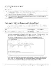
... System Mode : 1.0 Software Version : 7.8.1.0 Unit Type Serial Number Part Number Revision * 0 S25-01-GE-24P DL277000000 7590004800 B 0 S50-PWR-AC N/A N/A N/A 0 S50-FAN N/A N/A N/A * - After the switch boots up (the status messages stop), press Enter twice to power (there is included with your system. Task Display the installed FTOS version and S-Series model. The following screenshot illustrates the expected output of the S-Series switch. You should be included with your system. 2 Basic Layer 2 Setup and Buffer...
... System Mode : 1.0 Software Version : 7.8.1.0 Unit Type Serial Number Part Number Revision * 0 S25-01-GE-24P DL277000000 7590004800 B 0 S50-PWR-AC N/A N/A N/A 0 S50-FAN N/A N/A N/A * - After the switch boots up (the status messages stop), press Enter twice to power (there is included with your system. Task Display the installed FTOS version and S-Series model. The following screenshot illustrates the expected output of the S-Series switch. You should be included with your system. 2 Basic Layer 2 Setup and Buffer...

