Installing the S25P System
Page 9
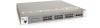
... and Supplying Power on page 27. Chapter 1 S25P System Overview The Force10 Networks S25P (Cat# S25-01-GE-24P) is a high performance, low cost, stackable, Layer 2 switch/Layer 3 router that displays activity of the S25P-DC, see Connecting Stack Ports (optional) on the S25P-DC (cat.# S25-01-GE-24P-DC). Figure 1 The S25P (Front View) Stack ID Indicator LED Status Panel...
... and Supplying Power on page 27. Chapter 1 S25P System Overview The Force10 Networks S25P (Cat# S25-01-GE-24P) is a high performance, low cost, stackable, Layer 2 switch/Layer 3 router that displays activity of the S25P-DC, see Connecting Stack Ports (optional) on the S25P-DC (cat.# S25-01-GE-24P-DC). Figure 1 The S25P (Front View) Stack ID Indicator LED Status Panel...
Installing the S25P System
Page 17
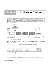
...01-12G-2S S50-01-24G-1S The system supports inserting the modules in any combination of slots (although connecting all four ports of stack port). See Connecting Stack Ports (optional) on page 28 Warning: As with all electrical devices of the chassis. Chapter 3 Installing the S25P To install the S25P system, Force10...its components. Inserting Optional Modules (10-Gigabit or Stacking) The S25P (catalog name S25-01-GE-24P) has two expansion slots in this system. Installing the S25P System 17 S25P-DC on page 25. So, for stacking. Electrostatic discharge (ESD) damage can occur ...
...01-12G-2S S50-01-24G-1S The system supports inserting the modules in any combination of slots (although connecting all four ports of stack port). See Connecting Stack Ports (optional) on page 28 Warning: As with all electrical devices of the chassis. Chapter 3 Installing the S25P To install the S25P system, Force10...its components. Inserting Optional Modules (10-Gigabit or Stacking) The S25P (catalog name S25-01-GE-24P) has two expansion slots in this system. Installing the S25P System 17 S25P-DC on page 25. So, for stacking. Electrostatic discharge (ESD) damage can occur ...
Installing the S25P System
Page 28
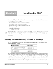
... of the S25P (on the right as you face the front of the chassis) and then to unplated metal contact surfaces. name S25-01-GE-24P-DC) has two DC terminal blocks on the left of antioxidant paste to the power source (see also Figure 4 on the right. The terminal block on...). Internationally, follow local safety codes.) Before you are connecting both terminal blocks, do not supply power until both terminal blocks are connected. The S25P-DC uses the power supplies in the United States. Cables must provide your site to ensure an adequate chassis ground. 4 Connect the -48 V and ...
... of the S25P (on the right as you face the front of the chassis) and then to unplated metal contact surfaces. name S25-01-GE-24P-DC) has two DC terminal blocks on the left of antioxidant paste to the power source (see also Figure 4 on the right. The terminal block on...). Internationally, follow local safety codes.) Before you are connecting both terminal blocks, do not supply power until both terminal blocks are connected. The S25P-DC uses the power supplies in the United States. Cables must provide your site to ensure an adequate chassis ground. 4 Connect the -48 V and ...
Installing the S25P System
Page 47
... a unit from a stack 25 removing battery 37 requesting replacement hardware 43 RJ-45 installation 29 S S25-01-GE-48P (S25P catalog name) 17 S25P front view 9 S25P rear view 9 S25P status information 11 S25P switch catalog name 9 S25P-DC 9 S50V front view 15, 28 S50V rear view 15 Safety Standards 36 screws for rack...
... a unit from a stack 25 removing battery 37 requesting replacement hardware 43 RJ-45 installation 29 S S25-01-GE-48P (S25P catalog name) 17 S25P front view 9 S25P rear view 9 S25P status information 11 S25P switch catalog name 9 S25P-DC 9 S50V front view 15, 28 S50V rear view 15 Safety Standards 36 screws for rack...

