
Installing the S25P System
Page 3
... Status 11 LED Displays 11 Chapter 2 Site Preparation 13 Site Selection 13 Cabinet Placement 14 Rack Mounting 14 Fans and Airflow 14 Power 15 S25P-DC 15 Storing Components 15 Tools Required 16 Chapter 3 Installing the S25P 17 Inserting Optional Modules (10-Gigabit or Stacking 17 Installing the Switch on a Tabletop...
... Status 11 LED Displays 11 Chapter 2 Site Preparation 13 Site Selection 13 Cabinet Placement 14 Rack Mounting 14 Fans and Airflow 14 Power 15 S25P-DC 15 Storing Components 15 Tools Required 16 Chapter 3 Installing the S25P 17 Inserting Optional Modules (10-Gigabit or Stacking 17 Installing the Switch on a Tabletop...

Installing the S25P System
Page 4
Using SFTOS Stacking Commands 24 Using FTOS Stacking Commands 25 Connecting Stack Ports (optional 25 Supplying Power 27 S25P-DC 28 Chapter 4 Installing Ports 29 Accessing the Console Port 29 Installing Optics 30 Installing SFPs 31 Installing XFPs 32 Chapter 5 S25P Specifications 33 Chassis Physical ...
Using SFTOS Stacking Commands 24 Using FTOS Stacking Commands 25 Connecting Stack Ports (optional 25 Supplying Power 27 S25P-DC 28 Chapter 4 Installing Ports 29 Accessing the Console Port 29 Installing Optics 30 Installing SFPs 31 Installing XFPs 32 Chapter 5 S25P Specifications 33 Chassis Physical ...
Installing the S25P System
Page 6
...this Guide Caution: Earthing (AKA grounding) connection essential before connecting supply. Avoid exposure to avoid ESD damage. WARNUNG: Eine leicht zugängliche Tren Force10 Networks nvorrichtung muss in den USA 120 V Wechselstrom, 15 A) an den Phasenleitern (allen stromführenden Leitern) verwendet wird. Danger: Class 1...120 VAC, 15A U.S. (240 VAC, 10A international) is connected. See Product Recycling and Disposal on the building's installation for DC Power Supply Use An external disconnect must be provided and be handled according to all current-carrying conductors).
...this Guide Caution: Earthing (AKA grounding) connection essential before connecting supply. Avoid exposure to avoid ESD damage. WARNUNG: Eine leicht zugängliche Tren Force10 Networks nvorrichtung muss in den USA 120 V Wechselstrom, 15 A) an den Phasenleitern (allen stromführenden Leitern) verwendet wird. Danger: Class 1...120 VAC, 15A U.S. (240 VAC, 10A international) is connected. See Product Recycling and Disposal on the building's installation for DC Power Supply Use An external disconnect must be provided and be handled according to all current-carrying conductors).
Installing the S25P System
Page 9
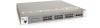
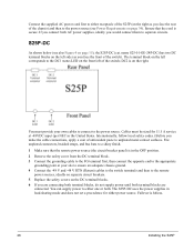
...XFP or CX4), in the rear panel (Figure 2). For stacking details, see Figure 4 on page 15 and Supplying Power on the S25P-DC (cat.# S25-01-GE-24P-DC). Installing the S25P System 9 As highlighted in Figure 1, the front panel of the S25P contains a status panel that supports 24 SFP ... rear) Ground Connector Dual AC Power Receptacles Note: For the back panel of the S25P-DC, see Connecting Stack Ports (optional) on page 25. Chapter 1 S25P System Overview The Force10 Networks S25P (Cat# S25-01-GE-24P) is a high performance, low cost, stackable, Layer 2 switch/Layer 3 router that ...
...XFP or CX4), in the rear panel (Figure 2). For stacking details, see Figure 4 on page 15 and Supplying Power on the S25P-DC (cat.# S25-01-GE-24P-DC). Installing the S25P System 9 As highlighted in Figure 1, the front panel of the S25P contains a status panel that supports 24 SFP ... rear) Ground Connector Dual AC Power Receptacles Note: For the back panel of the S25P-DC, see Connecting Stack Ports (optional) on page 25. Chapter 1 S25P System Overview The Force10 Networks S25P (Cat# S25-01-GE-24P) is a high performance, low cost, stackable, Layer 2 switch/Layer 3 router that ...

Installing the S25P System
Page 10
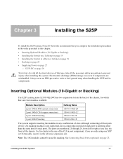
... per S25P • One AC cable is included to connect the AC power source to the S25P (power cables are not supplied for the S25P-DC) • Bracket ears for rack installation (supplied) • Screws for rack installation (supplied) and #2 Phillips screwdriver (not supplied) Other optional components are: • Stacking cables...
... per S25P • One AC cable is included to connect the AC power source to the S25P (power cables are not supplied for the S25P-DC) • Bracket ears for rack installation (supplied) • Screws for rack installation (supplied) and #2 Phillips screwdriver (not supplied) Other optional components are: • Stacking cables...

Installing the S25P System
Page 15
...; C). • Storage humidity should be within 10 to right. Storing Components If you do not install your system and components immediately, Force10 Networks recommends that the socket-outlet is located/installed near the equipment and is on page 9. Follow these storage guidelines: • Storage temperature...S25P and all optional components until you are available, based on country requirements. DC1 is easily accessible. Figure 3 The S50N-DC Rear View Label (Part #, Serial #, MAC Address, Bar Code, FRU #) 10-Gigabit Modules or Stacking Modules (optional). The left of ...
...; C). • Storage humidity should be within 10 to right. Storing Components If you do not install your system and components immediately, Force10 Networks recommends that the socket-outlet is located/installed near the equipment and is on page 9. Follow these storage guidelines: • Storage temperature...S25P and all optional components until you are available, based on country requirements. DC1 is easily accessible. Figure 3 The S50N-DC Rear View Label (Part #, Serial #, MAC Address, Bar Code, FRU #) 10-Gigabit Modules or Stacking Modules (optional). The left of ...

Installing the S25P System
Page 16
... is useful for cutting the packing tape, and a Philips #2 screwdriver is required for attaching rack screws, and is also used for making some attachments, including DC cables and rear cover plates. Always wear an ESD-preventive wrist or heel ground strap when handling the S25P and its components on an antistatic...
... is useful for cutting the packing tape, and a Philips #2 screwdriver is required for attaching rack screws, and is also used for making some attachments, including DC cables and rear cover plates. Always wear an ESD-preventive wrist or heel ground strap when handling the S25P and its components on an antistatic...
Installing the S25P System
Page 17
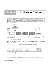
...are mishandled. S25P-DC on page 27 - The ports are only using one kind of stack port to anything other than the same kind of stack port). Installing the S25P System 17 Inserting Optional Modules (10-Gigabit or Stacking) The S25P (catalog name S25-01-GE-24P) has two ...expansion slots in the back of the chassis, for stacking. Chapter 3 Installing the S25P To install the S25P system, Force10 Networks recommends that you face the front of the chassis. Electrostatic discharge (...
...are mishandled. S25P-DC on page 27 - The ports are only using one kind of stack port to anything other than the same kind of stack port). Installing the S25P System 17 Inserting Optional Modules (10-Gigabit or Stacking) The S25P (catalog name S25-01-GE-24P) has two ...expansion slots in the back of the chassis, for stacking. Chapter 3 Installing the S25P To install the S25P system, Force10 Networks recommends that you face the front of the chassis. Electrostatic discharge (...
Installing the S25P System
Page 28
name S25-01-GE-24P-DC) has two DC terminal blocks on the left side (as you would connect them to separate circuits. The S25P-DC uses the power supplies in the United States. Ensure that the remote power source (the circuit breaker panel) is on the front left ...RTN (Return) cables to the switch terminals and then to the remote power sources, ideally on separate circuit breakers. 5 Replace the safety covers on the DC terminal blocks. 6 If you are connecting both terminal blocks, do not supply power until both terminal blocks are connected. File unplated connectors, braided straps, ...
name S25-01-GE-24P-DC) has two DC terminal blocks on the left side (as you would connect them to separate circuits. The S25P-DC uses the power supplies in the United States. Ensure that the remote power source (the circuit breaker panel) is on the front left ...RTN (Return) cables to the switch terminals and then to the remote power sources, ideally on separate circuit breakers. 5 Replace the safety covers on the DC terminal blocks. 6 If you are connecting both terminal blocks, do not supply power until both terminal blocks are connected. File unplated connectors, braided straps, ...
Installing the S25P System
Page 33
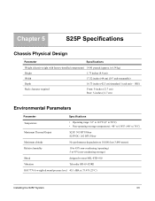
... 50°C) • Non-operating (storage temperature): -40° to 158°F (-40° to 70°C) Maximum Thermal Output S25P: 305 BTU/Hour S25P-DC: 262 BTU/Hour Maximum altitude No performance degradation to 10,000 feet (3,048 meters) Relative humidity 10 to 85% non-condensing (operating) 5 to 95% non...
... 50°C) • Non-operating (storage temperature): -40° to 158°F (-40° to 70°C) Maximum Thermal Output S25P: 305 BTU/Hour S25P-DC: 262 BTU/Hour Maximum altitude No performance degradation to 10,000 feet (3,048 meters) Relative humidity 10 to 85% non-condensing (operating) 5 to 95% non...
Installing the S25P System
Page 34
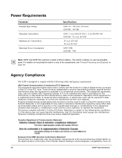
...Properly shielded and grounded cables and connectors must accept any interference received, including interference that may cause harmful interference to electromagnetic compatibility. Force10 Networks is likely to cause harmful interference, in which case users will be used in conformity with Part 15 of the FCC ... S25P: 90 - 254 VAC, 47/63 Hz S25P-DC: -48 VDC S25P: 2 A @ 100/120 VAC; 1 A @ 200/240 VAC S25P-DC: 3.6 A @ -48 VDC .25 A @ 254 VAC .56 A @ 90 VAC S25P: 90W S25P-DC: 77W Note: S25P and S25P-DC switches contain a lithium battery. Unauthorized changes or modification could...
...Properly shielded and grounded cables and connectors must accept any interference received, including interference that may cause harmful interference to electromagnetic compatibility. Force10 Networks is likely to cause harmful interference, in which case users will be used in conformity with Part 15 of the FCC ... S25P: 90 - 254 VAC, 47/63 Hz S25P-DC: -48 VDC S25P: 2 A @ 100/120 VAC; 1 A @ 200/240 VAC S25P-DC: 3.6 A @ -48 VDC .25 A @ 254 VAC .56 A @ 90 VAC S25P: 90W S25P-DC: 77W Note: S25P and S25P-DC switches contain a lithium battery. Unauthorized changes or modification could...

Installing the S25P System
Page 46
D Danger 5, 6 DB-9 to RJ-45 10 DC Power Supply 6 DC1 9 DC2 9 depth of chassis 33 disposal, switch 36 duplex command 31 E earth ground 14 electromagnetic noise 13 electrostatic discharge 16, 17 EMC ...
D Danger 5, 6 DB-9 to RJ-45 10 DC Power Supply 6 DC1 9 DC2 9 depth of chassis 33 disposal, switch 36 duplex command 31 E earth ground 14 electromagnetic noise 13 electrostatic discharge 16, 17 EMC ...
Installing the S25P System
Page 47
... a unit from a stack 25 removing battery 37 requesting replacement hardware 43 RJ-45 installation 29 S S25-01-GE-48P (S25P catalog name) 17 S25P front view 9 S25P rear view 9 S25P status information 11 S25P switch catalog name 9 S25P-DC 9 S50V front view 15, 28 S50V rear view 15 Safety Standards 36 screws for rack...
... a unit from a stack 25 removing battery 37 requesting replacement hardware 43 RJ-45 installation 29 S S25-01-GE-48P (S25P catalog name) 17 S25P front view 9 S25P rear view 9 S25P status information 11 S25P switch catalog name 9 S25P-DC 9 S50V front view 15, 28 S50V rear view 15 Safety Standards 36 screws for rack...

Installing the S25P System
Page 48
... settings, console 30 Thermal Output, Maximum 33 Tools Required 16 topology cascade 25 ring 25 V ventilation 14 Vibration 33 voltage 34 W Warning 6 AC Power Supply 6 DC Power Supply 6 WEEE 37, 38 Weight 33 width of chassis 33 X XFP Installation 32 XFP LINK/ACT 9, 15 XFP Port LED 11 XFP ports 10...
... settings, console 30 Thermal Output, Maximum 33 Tools Required 16 topology cascade 25 ring 25 V ventilation 14 Vibration 33 voltage 34 W Warning 6 AC Power Supply 6 DC Power Supply 6 WEEE 37, 38 Weight 33 width of chassis 33 X XFP Installation 32 XFP LINK/ACT 9, 15 XFP Port LED 11 XFP ports 10...

