
Quick Start Guide
Page 7
... is the only unit in the rack. • When mounting this unit in the rack. Follow these steps to both the C150 and C300 chassis. Install the chassis into a 19-inch equipment rack: Installing the Hardware 5 NOTE: Unless stated otherwise, the installation instructions below . ...special precautions to prevent injury when installing this system. Lifting by the chassis shelves or power supply openings might damage the chassis. Installing the Chassis To install the C150/300 chassis, Dell Force10 recommends that the system remains stable. As with care. Installing the Chassis in the ...
... is the only unit in the rack. • When mounting this unit in the rack. Follow these steps to both the C150 and C300 chassis. Install the chassis into a 19-inch equipment rack: Installing the Hardware 5 NOTE: Unless stated otherwise, the installation instructions below . ...special precautions to prevent injury when installing this system. Lifting by the chassis shelves or power supply openings might damage the chassis. Installing the Chassis To install the C150/300 chassis, Dell Force10 recommends that the system remains stable. As with care. Installing the Chassis in the ...

Quick Start Guide
Page 11
... installer to your C150 system until the power supplies and fan tray are not field serviceable. AC Power Supplies • The C150 requires only one AC power supply to operate, but Dell Force10 recommends a one-plus-one redundancy configuration, so a minimum of two power supplies is recommended. • The C300 requires a minimum of two AC power supplies to the appropriate branch circuit protection...
... installer to your C150 system until the power supplies and fan tray are not field serviceable. AC Power Supplies • The C150 requires only one AC power supply to operate, but Dell Force10 recommends a one-plus-one redundancy configuration, so a minimum of two power supplies is recommended. • The C300 requires a minimum of two AC power supplies to the appropriate branch circuit protection...

Quick Start Guide
Page 12
... range supports a different power supply configuration. WARNING: The C300 operates in all unused PSU slots. Installing DC Power Supplies • The C150 requires at least one DC PEM for operation, but Dell Force10 recommends a one-plus -one redundancy configuration. The power cord plugs must be ... Leakage Current (High Touch Current) in AC-powered systems with more than 3+1 power supplies. Those DC PEMs are inserted in slots 0 and 2. • The C300 requires at least one DC PEM for operation, but Dell Force10 recommends a one-plus -one redundancy configuration....
... range supports a different power supply configuration. WARNING: The C300 operates in all unused PSU slots. Installing DC Power Supplies • The C150 requires at least one DC PEM for operation, but Dell Force10 recommends a one-plus -one redundancy configuration. The power cord plugs must be ... Leakage Current (High Touch Current) in AC-powered systems with more than 3+1 power supplies. Those DC PEMs are inserted in slots 0 and 2. • The C300 requires at least one DC PEM for operation, but Dell Force10 recommends a one-plus -one redundancy configuration....

Quick Start Guide
Page 13
... Cover Handle Retaining Latch BLNK fn003lp fn003lp fn00012lpp BLNK BLNK BLNK Power Supply Blank C300 Power Entry Module Installation fn0002lp Installing the Hardware 11 CAUTION: Some CH-C300 chassis may require Dell Force10 assistance when using some DC power supplies. • To protect against high-voltage shock, install a power supply blank (CC-CBLNK-PWR) on the PEM front panel) to the...
... Cover Handle Retaining Latch BLNK fn003lp fn003lp fn00012lpp BLNK BLNK BLNK Power Supply Blank C300 Power Entry Module Installation fn0002lp Installing the Hardware 11 CAUTION: Some CH-C300 chassis may require Dell Force10 assistance when using some DC power supplies. • To protect against high-voltage shock, install a power supply blank (CC-CBLNK-PWR) on the PEM front panel) to the...

Quick Start Guide
Page 18
... you reinspect your equipment rack and chassis. To supply power to the chassis, Dell Force10 recommends that the power source complies with the system input power requirements. 2 Energize the remote power source or outlet. 16 Installing the Hardware Each range supports a different supply configuration. CAUTION: The C300 operates in all unused power supply slots. CAUTION: Never operate the system without a fan...
... you reinspect your equipment rack and chassis. To supply power to the chassis, Dell Force10 recommends that the power source complies with the system input power requirements. 2 Energize the remote power source or outlet. 16 Installing the Hardware Each range supports a different supply configuration. CAUTION: The C300 operates in all unused power supply slots. CAUTION: Never operate the system without a fan...

Quick Start Guide
Page 19
... lit as long as the diagnostic programs run. Step Task 3 On the C150, toggle the switch on the AC power supplies to the ON (top) position. On the C300, toggle the switch on the AC power supplies to the ON (right) position. If the fans are not lit green: • Check that the fan tray... is properly installed. • If the fan tray LED remains unlit, power down the unit, and replace the fan tray. ...
... lit as long as the diagnostic programs run. Step Task 3 On the C150, toggle the switch on the AC power supplies to the ON (top) position. On the C300, toggle the switch on the AC power supplies to the ON (right) position. If the fans are not lit green: • Check that the fan tray... is properly installed. • If the fan tray LED remains unlit, power down the unit, and replace the fan tray. ...

Quick Start Guide
Page 20
... 200/240 V lines.) 7 A @ 200 V per AC Power Supply 6 A @ 240 V per AC Power Supply Maximum System Power Input 4.5 KVA @ 100/120 V 4.4 KVA @ 200/240 V C300 Specifications 100-240 VAC 50/60 Hz 14 A @ 100 V per AC Power Supply 12 A @ 120 VAC per AC Power Supply 7 A @ 200 VAC per AC Power Supply 6 A @ 240 VAC per AC Power Supply 8.7 KVA @ 100/120 V 8.5 KVA @ 200/240 V 18 Installing...
... 200/240 V lines.) 7 A @ 200 V per AC Power Supply 6 A @ 240 V per AC Power Supply Maximum System Power Input 4.5 KVA @ 100/120 V 4.4 KVA @ 200/240 V C300 Specifications 100-240 VAC 50/60 Hz 14 A @ 100 V per AC Power Supply 12 A @ 120 VAC per AC Power Supply 7 A @ 200 VAC per AC Power Supply 6 A @ 240 VAC per AC Power Supply 8.7 KVA @ 100/120 V 8.5 KVA @ 200/240 V 18 Installing...

C300 Hardware Installation Guide
Page 3
... Installation Process 12 3 Preparing the Site Site Selection Criteria 13 Rack Mounting 13 Requirements 14 Shipping and Storing Components 14 4 Installing C300 Fan Tray Removing the Fan Tray 16 Fan Speed 16 5 Installing RPMs and Line Cards Route Processor Modules 17 RPM Label and LEDs 17 Line ... Port 23 Cable and Adapter Pin Assignments 23 Accessing the Console with a DB-9 Adapter 24 Accessing the Console with a DB-25 Adapter 24 7 Installing AC Power Supplies Installing the AC Power Supply 29 Power Cord Requirements 30 Power Over Ethernet (PoE 31 Contents | 3
... Installation Process 12 3 Preparing the Site Site Selection Criteria 13 Rack Mounting 13 Requirements 14 Shipping and Storing Components 14 4 Installing C300 Fan Tray Removing the Fan Tray 16 Fan Speed 16 5 Installing RPMs and Line Cards Route Processor Modules 17 RPM Label and LEDs 17 Line ... Port 23 Cable and Adapter Pin Assignments 23 Accessing the Console with a DB-9 Adapter 24 Accessing the Console with a DB-25 Adapter 24 7 Installing AC Power Supplies Installing the AC Power Supply 29 Power Cord Requirements 30 Power Over Ethernet (PoE 31 Contents | 3

C300 Hardware Installation Guide
Page 4
www.dell.com | support.dell.com 8 Installing DC Power Entry Modules Recommended Normal Operating Conditions 33 Redundancy 33 Cable and Connector Requirements 34 Installing a DC PEM 34 Status LED 37 Removing a DC PEM 37 9 Powering Up Supplying 39 Booting from the BOOT_USER Prompt 41 10 Removing and Replacing Components... Removing and Replacing the Fan Tray 43 Removing and Replacing Power Supply Units 44 Removing and Replacing a Line Card 45 11 Installing the Chassis Safety Considerations 49 Installing the Chassis into ...
www.dell.com | support.dell.com 8 Installing DC Power Entry Modules Recommended Normal Operating Conditions 33 Redundancy 33 Cable and Connector Requirements 34 Installing a DC PEM 34 Status LED 37 Removing a DC PEM 37 9 Powering Up Supplying 39 Booting from the BOOT_USER Prompt 41 10 Removing and Replacing Components... Removing and Replacing the Fan Tray 43 Removing and Replacing Power Supply Units 44 Removing and Replacing a Line Card 45 11 Installing the Chassis Safety Considerations 49 Installing the Chassis into ...

C300 Hardware Installation Guide
Page 7
... contains two AC- WARNING: The installation of this Guide This guide provides site preparation recommendations and instructions for RPMs, power supplies, and line cards. Please read these alerts and heed their warnings and cautions. Table 1-1. cords. Visible and invisible...This equipment contains optical transceivers, which comply with all of the necessary components, including slot blanks for installing the Dell Force10 C300 chassis, fan tray, power supply units (supplies), route processor modules (RPMs), and line cards. 1 About this equipment shall be emitted from the aperture ...
... contains two AC- WARNING: The installation of this Guide This guide provides site preparation recommendations and instructions for RPMs, power supplies, and line cards. Please read these alerts and heed their warnings and cautions. Table 1-1. cords. Visible and invisible...This equipment contains optical transceivers, which comply with all of the necessary components, including slot blanks for installing the Dell Force10 C300 chassis, fan tray, power supply units (supplies), route processor modules (RPMs), and line cards. 1 About this equipment shall be emitted from the aperture ...

C300 Hardware Installation Guide
Page 8
... Verdrahtung eingebaut sein. Ensure that a fuse or circuit breaker no larger than one power supply connection; ATTENTION: Pour ce qui est de la protection contre les courts-circuits (surtension), ce produit dépend de l'installation électrique du local. Dell Force10 recommends the use of used on the phase conductors (all current-carrying conductors...
... Verdrahtung eingebaut sein. Ensure that a fuse or circuit breaker no larger than one power supply connection; ATTENTION: Pour ce qui est de la protection contre les courts-circuits (surtension), ce produit dépend de l'installation électrique du local. Dell Force10 recommends the use of used on the phase conductors (all current-carrying conductors...

C300 Hardware Installation Guide
Page 11
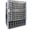
...C300 Chassis (Front View) Front Mount Bracket 4-Port Fiber Line Card Fan Tray 0 1 2 3 R0 R1 4 SFM Status Master ACTIVE Alarm SFM Status Master ACTIVE Alarm RJ-45 Console RJ-45 Console Compact Flash Compact Flash Reset Reset BLNK 5 BLNK 6 BLNK 7 48-Port Line Card Route Processor Module Line Card Blank AC Power Supply... Unit l l l O O O BLNK BLNK BLNK BLNK BLNK AC Power Supply Unit Blank fnC0007mp Installing and Maintaining the C150 System 11 Figure 2-1. The 10-slot system ...
...C300 Chassis (Front View) Front Mount Bracket 4-Port Fiber Line Card Fan Tray 0 1 2 3 R0 R1 4 SFM Status Master ACTIVE Alarm SFM Status Master ACTIVE Alarm RJ-45 Console RJ-45 Console Compact Flash Compact Flash Reset Reset BLNK 5 BLNK 6 BLNK 7 48-Port Line Card Route Processor Module Line Card Blank AC Power Supply... Unit l l l O O O BLNK BLNK BLNK BLNK BLNK AC Power Supply Unit Blank fnC0007mp Installing and Maintaining the C150 System 11 Figure 2-1. The 10-slot system ...

C300 Hardware Installation Guide
Page 12
... Requirements Component Minimum Backplane (factory installed) 1 Fan tray 1 RPM 1 Line card 1 AC Power Supply 2 DC Power Entry Module 2 Maximum 1 1 2 8 8 8 Field-Replaceable No Yes Yes Yes Yes Yes C300 System Installation Process The Dell Force10 recommended installation process is described below. Relevant Section in a rack. 4 Install the fan tray. 5 Install the RPMs and line cards. 6 Connect console...
... Requirements Component Minimum Backplane (factory installed) 1 Fan tray 1 RPM 1 Line card 1 AC Power Supply 2 DC Power Entry Module 2 Maximum 1 1 2 8 8 8 Field-Replaceable No Yes Yes Yes Yes Yes C300 System Installation Process The Dell Force10 recommended installation process is described below. Relevant Section in a rack. 4 Install the fan tray. 5 Install the RPMs and line cards. 6 Connect console...

C300 Hardware Installation Guide
Page 27
The slots accept either AC Power Supply Units (PSUs) or DC Power Entry Modules (PEMs). • Dell Force10 does not support the use of a combination of AC and DC power supplies. • If you select AC, the C300 requires a minimum of two AC power supplies to operate, but Dell Force10 recommends a two-plus-one redundancy configuration, so a minimum of the installer to provide...
The slots accept either AC Power Supply Units (PSUs) or DC Power Entry Modules (PEMs). • Dell Force10 does not support the use of a combination of AC and DC power supplies. • If you select AC, the C300 requires a minimum of two AC power supplies to operate, but Dell Force10 recommends a two-plus-one redundancy configuration, so a minimum of the installer to provide...

C300 Hardware Installation Guide
Page 29
... must be replaced. Installing the AC Power Supply WARNING: Use only the power cord supplied with the power supply. Do not supply power to light red, there must be at least one LED as described in the chassis. The unit is beyond its limits. NOTE: For a unit LED to your C300 system until the power supplies, blank panels, fan tray, RPMs...
... must be replaced. Installing the AC Power Supply WARNING: Use only the power cord supplied with the power supply. Do not supply power to light red, there must be at least one LED as described in the chassis. The unit is beyond its limits. NOTE: For a unit LED to your C300 system until the power supplies, blank panels, fan tray, RPMs...

C300 Hardware Installation Guide
Page 30
WARNING: The C300 operates in either of the power supply. See Figure 7-1 for the remaining power supplies. The following are Dell Force10 supplied plug types. Dell Force10 recommends installing power supplies starting from the left most power supply slot. All power plugs must have an appropriately sized plug that the socket-outlet is located/ installed near the equipment and is easily accessible. www.dell.com | support.dell.com...
WARNING: The C300 operates in either of the power supply. See Figure 7-1 for the remaining power supplies. The following are Dell Force10 supplied plug types. Dell Force10 recommends installing power supplies starting from the left most power supply slot. All power plugs must have an appropriately sized plug that the socket-outlet is located/ installed near the equipment and is easily accessible. www.dell.com | support.dell.com...

C300 Hardware Installation Guide
Page 31
... (UTP) cable. A minimum of four AC power supplies are enabled with PoE. Power Over Ethernet (PoE) The C-Series can transmit power to enable PoE, and 77 ports can be enabled per Power Supply Unit Power Supply Units 1 2 3 4 5 6 7 8 Max PoE Ports - - - 77 154 231 308 384 Installing AC Power Supplies | 31 Table 7-2. The chassis transmits power to connected IEEE 802.3af-compliant...
... (UTP) cable. A minimum of four AC power supplies are enabled with PoE. Power Over Ethernet (PoE) The C-Series can transmit power to enable PoE, and 77 ports can be enabled per Power Supply Unit Power Supply Units 1 2 3 4 5 6 7 8 Max PoE Ports - - - 77 154 231 308 384 Installing AC Power Supplies | 31 Table 7-2. The chassis transmits power to connected IEEE 802.3af-compliant...

C300 Hardware Installation Guide
Page 33
...install a supply blank (CC-C-BLNK-PWR) on page 35). 8 Installing DC Power Entry Modules The C300 has eight supply slots at least one DC PEM for operation, but Dell Force10 recommends a one-plus-one redundancy configuration. Please contact the Dell Force10 TAC if you select DC, the C300 requires at.... Input voltage Input Ranges -44V (minimum) -48V (typical) -55V (maximum) Table 8-2. The slots accept either AC Power Supplies (PSUs) or DC Power Entry Modules (PEMs). Installing DC Power Entry Modules | 33 NOTE: Some CH-C300 chassis may require Dell Force10 assistance when using some DC...
...install a supply blank (CC-C-BLNK-PWR) on page 35). 8 Installing DC Power Entry Modules The C300 has eight supply slots at least one DC PEM for operation, but Dell Force10 recommends a one-plus-one redundancy configuration. Please contact the Dell Force10 TAC if you select DC, the C300 requires at.... Input voltage Input Ranges -44V (minimum) -48V (typical) -55V (maximum) Table 8-2. The slots accept either AC Power Supplies (PSUs) or DC Power Entry Modules (PEMs). Installing DC Power Entry Modules | 33 NOTE: Some CH-C300 chassis may require Dell Force10 assistance when using some DC...

C300 Hardware Installation Guide
Page 43
...a fan within a fan tray is configured). Adhere to the following C300 components: • Removing and Replacing the Fan Tray • Removing and Replacing Power Supply Units • Removing and Replacing a Line Card When a component fails, the C300 System system triggers an alarm LED (located on the active RPM), ... surface and anti-static bags when they are mishandled. To remove and replace the fan tray, you replace the fan tray, the C300 system will operate safely for more information on alarms. WARNING: Electrostatic discharge (ESD) damage can occur when components are not installed....
...a fan within a fan tray is configured). Adhere to the following C300 components: • Removing and Replacing the Fan Tray • Removing and Replacing Power Supply Units • Removing and Replacing a Line Card When a component fails, the C300 System system triggers an alarm LED (located on the active RPM), ... surface and anti-static bags when they are mishandled. To remove and replace the fan tray, you replace the fan tray, the C300 system will operate safely for more information on alarms. WARNING: Electrostatic discharge (ESD) damage can occur when components are not installed....

C300 Hardware Installation Guide
Page 44
...top and bottom of the fan tray using a #2 Phillips screwdriver. Removing and Replacing Power Supply Units WARNING: Do not remove a panel blank unless you are operating your C300 chassis with a redundant power supply, you are ready to pull the fan tray out approximately two inches from the chassis..., if configured, an SNMP trap. A power supply failure is flush with only two power supplies (the minimum), you must be replaced. Secure the fan tray into that slot. If you are operating your C300 system with the chassis. www.dell.com | support.dell.com Figure 10-1. Fan Tray (Left) ...
...top and bottom of the fan tray using a #2 Phillips screwdriver. Removing and Replacing Power Supply Units WARNING: Do not remove a panel blank unless you are operating your C300 chassis with a redundant power supply, you are ready to pull the fan tray out approximately two inches from the chassis..., if configured, an SNMP trap. A power supply failure is flush with only two power supplies (the minimum), you must be replaced. Secure the fan tray into that slot. If you are operating your C300 system with the chassis. www.dell.com | support.dell.com Figure 10-1. Fan Tray (Left) ...


