
Quick Start Guide
Page 5
...Series About this Guide This document is intended as a Quick Start Guide to the following documents: Documentation Hardware installation and power-up and running and ready for C- FTOS Release Notes for configuration. For complete installation and configuration information, refer to... get new systems up instructions Software configuration Command line interface Latest updates C150 C300 Installing and Maintaining Installing and Maintaining the C150 System the C300 System FTOS Configuration Guide FTOS Configuration Guide FTOS Command Line Reference Guide FTOS Command Line...
...Series About this Guide This document is intended as a Quick Start Guide to the following documents: Documentation Hardware installation and power-up and running and ready for C- FTOS Release Notes for configuration. For complete installation and configuration information, refer to... get new systems up instructions Software configuration Command line interface Latest updates C150 C300 Installing and Maintaining Installing and Maintaining the C150 System the C300 System FTOS Configuration Guide FTOS Configuration Guide FTOS Command Line Reference Guide FTOS Command Line...

Quick Start Guide
Page 7
... rack, you complete the installation procedures in the rack. Lifting by the chassis shelves or power supply openings might damage the chassis. Follow these steps to ensure your safety: • ...when lifting or moving the chassis. Installing the Chassis To install the C150/300 chassis, Dell Force10 recommends that the system remains stable. WARNING: To prevent bodily injury when mounting or ... to ensure that you must take all necessary safety precautions to both the C150 and C300 chassis. Avoid dropping the switch or its field replaceable units. The following guidelines are ...
... rack, you complete the installation procedures in the rack. Lifting by the chassis shelves or power supply openings might damage the chassis. Follow these steps to ensure your safety: • ...when lifting or moving the chassis. Installing the Chassis To install the C150/300 chassis, Dell Force10 recommends that the system remains stable. WARNING: To prevent bodily injury when mounting or ... to ensure that you must take all necessary safety precautions to both the C150 and C300 chassis. Avoid dropping the switch or its field replaceable units. The following guidelines are ...

Quick Start Guide
Page 10
... and nut on the stud. 6 Secure the nut with any DC PEM connection. File unplated connectors, braided straps, and bus bars to the DC powered chassis only. Attach a Ground Cable to the C150/300 DC Chassis WARNING: You must complete the ground connection before you make the cable connections. It... file and coat tinned, solder plated, or silver-plated connectors or other plated connection surfaces, such as those on the PEM front panel. The AC power cord is the single stud below the safety cover. 2 Remove the nut and washer from the ground stud. 3 Apply a coat of the grounding ...
... and nut on the stud. 6 Secure the nut with any DC PEM connection. File unplated connectors, braided straps, and bus bars to the DC powered chassis only. Attach a Ground Cable to the C150/300 DC Chassis WARNING: You must complete the ground connection before you make the cable connections. It... file and coat tinned, solder plated, or silver-plated connectors or other plated connection surfaces, such as those on the PEM front panel. The AC power cord is the single stud below the safety cover. 2 Remove the nut and washer from the ground stud. 3 Apply a coat of the grounding ...

Quick Start Guide
Page 11
...-plus-one redundancy configuration, so a minimum of three power supplies is used on the phase conductors (all unused power supply slots. • Connect the AC power supply to operate, but Dell Force10 recommends a one-plus-one redundancy configuration, so a minimum of two power supplies is recommended. • The C300 requires a minimum of the installer to your C150...
...-plus-one redundancy configuration, so a minimum of three power supplies is used on the phase conductors (all unused power supply slots. • Connect the AC power supply to operate, but Dell Force10 recommends a one-plus-one redundancy configuration, so a minimum of two power supplies is recommended. • The C300 requires a minimum of the installer to your C150...

Quick Start Guide
Page 12
... in the face of two voltage ranges. Those DC PEMs are inserted in slots 0 and 2. • The C300 requires at least one DC PEM for operation, but Dell Force10 recommends a one-plus -one redundancy configuration. The power cord plugs must be secured to the building outlets by the qualified chassis installer or a qualified electrician...
... in the face of two voltage ranges. Those DC PEMs are inserted in slots 0 and 2. • The C300 requires at least one DC PEM for operation, but Dell Force10 recommends a one-plus -one redundancy configuration. The power cord plugs must be secured to the building outlets by the qualified chassis installer or a qualified electrician...

Quick Start Guide
Page 13
... Switch Safety Cover Handle Retaining Latch BLNK fn003lp fn003lp fn00012lpp BLNK BLNK BLNK Power Supply Blank C300 Power Entry Module Installation fn0002lp Installing the Hardware 11 CAUTION: Some CH-C300 chassis may require Dell Force10 assistance when using some DC power supplies. Please contact the Dell Force10 TAC if you experience any difficulty during installation Step Task 1 Turn the...
... Switch Safety Cover Handle Retaining Latch BLNK fn003lp fn003lp fn00012lpp BLNK BLNK BLNK Power Supply Blank C300 Power Entry Module Installation fn0002lp Installing the Hardware 11 CAUTION: Some CH-C300 chassis may require Dell Force10 assistance when using some DC power supplies. Please contact the Dell Force10 TAC if you experience any difficulty during installation Step Task 1 Turn the...

Quick Start Guide
Page 14
...panel. - The C300 System accommodates eight line cards and two Route Processor Modules (RPMs). 12 Installing the Hardware a Verify that the arrow points down toward the rack rail. The two left-handed studs (closest to GND) are the return (+48V DC) connection. NOTE: Power cables must be ...The two right-handed studs (furthest from each of anti-oxidant paste to the connector studs, if required. The cable attached to the remote power sources. The cable attached to exceed 4 ft/lbs). 8 Replace the safety cover and tighten the captive screw. The safety cover can then...
...panel. - The C300 System accommodates eight line cards and two Route Processor Modules (RPMs). 12 Installing the Hardware a Verify that the arrow points down toward the rack rail. The two left-handed studs (closest to GND) are the return (+48V DC) connection. NOTE: Power cables must be ...The two right-handed studs (furthest from each of anti-oxidant paste to the connector studs, if required. The cable attached to the remote power sources. The cable attached to exceed 4 ft/lbs). 8 Replace the safety cover and tighten the captive screw. The safety cover can then...

Quick Start Guide
Page 18
...range supports a different supply configuration. To supply power to the system: Step Task 1 Verify that you supply power to the chassis, Dell Force10 recommends that the power source complies with the system input power requirements. 2 Energize the remote power source or outlet. 16 Installing the Hardware As... number of two voltage ranges. Install blank panels in either of power supplies (given by the table below), as this causes high leakage current. Power Up Sequence Before you reinspect your equipment rack and chassis. C300 0 1 2 3 R0 R1 4 5 6 7 fnC0003mp NOTE...
...range supports a different supply configuration. To supply power to the system: Step Task 1 Verify that you supply power to the chassis, Dell Force10 recommends that the power source complies with the system input power requirements. 2 Energize the remote power source or outlet. 16 Installing the Hardware As... number of two voltage ranges. Install blank panels in either of power supplies (given by the table below), as this causes high leakage current. Power Up Sequence Before you reinspect your equipment rack and chassis. C300 0 1 2 3 R0 R1 4 5 6 7 fnC0003mp NOTE...

Quick Start Guide
Page 19
.... • If the fan tray LED remains unlit, power down the unit, and replace the fan tray. On the C300, toggle the switch on the AC power supplies to the chassis, the system performs a series of power-on self tests. After you supply power to the ON (top) position. On either system, ...toggle the switch on the DC power Over-Current Protector ON 4 The power supply LEDs should be...
.... • If the fan tray LED remains unlit, power down the unit, and replace the fan tray. On the C300, toggle the switch on the AC power supplies to the chassis, the system performs a series of power-on self tests. After you supply power to the ON (top) position. On either system, ...toggle the switch on the DC power Over-Current Protector ON 4 The power supply LEDs should be...

Quick Start Guide
Page 20
... V lines.) 7 A @ 200 V per AC Power Supply 6 A @ 240 V per AC Power Supply Maximum System Power Input 4.5 KVA @ 100/120 V 4.4 KVA @ 200/240 V C300 Specifications 100-240 VAC 50/60 Hz 14 A @ 100 V per AC Power Supply 12 A @ 120 VAC per AC Power Supply 7 A @ 200 VAC per AC Power Supply 6 A @ 240 VAC per AC Power Supply 8.7 KVA @ 100/120 V 8.5 KVA...
... V lines.) 7 A @ 200 V per AC Power Supply 6 A @ 240 V per AC Power Supply Maximum System Power Input 4.5 KVA @ 100/120 V 4.4 KVA @ 200/240 V C300 Specifications 100-240 VAC 50/60 Hz 14 A @ 100 V per AC Power Supply 12 A @ 120 VAC per AC Power Supply 7 A @ 200 VAC per AC Power Supply 6 A @ 240 VAC per AC Power Supply 8.7 KVA @ 100/120 V 8.5 KVA...

Quick Start Guide
Page 21
...@ 200/240 V Maximum Thermal 2,921 BTU/hour (856 W) Output at 100/120 V Maximum Thermal 2,850 BTU/hour (835 W) Output at 200/220 V DC Power Requirements Parameter C150 Specifications Nominal input voltage -44 to -55 V Maximum Current 32 A per DC PEM Draw (per DC PEM) Maximum system 800... W power consumption Maximum Thermal 2,457 BTU/hour (720 W) Output C300 Specifications 8,675 W @ 100/120 V 8,476 W @ 200/240 V 4,978 BTU/hour 4.864 BTU/hour C300 Specifications -44 to -55 V 32 A per DC PEM 1,460 W 4,231 BTU/hour ...
...@ 200/240 V Maximum Thermal 2,921 BTU/hour (856 W) Output at 100/120 V Maximum Thermal 2,850 BTU/hour (835 W) Output at 200/220 V DC Power Requirements Parameter C150 Specifications Nominal input voltage -44 to -55 V Maximum Current 32 A per DC PEM Draw (per DC PEM) Maximum system 800... W power consumption Maximum Thermal 2,457 BTU/hour (720 W) Output C300 Specifications 8,675 W @ 100/120 V 8,476 W @ 200/240 V 4,978 BTU/hour 4.864 BTU/hour C300 Specifications -44 to -55 V 32 A per DC PEM 1,460 W 4,231 BTU/hour ...

Quick Start Guide
Page 26
...2 data transmissions through an individual interface. Configure Layer 2 (Data Link) Mode Use the switchport command in the prompt. The default host name is Force10). no shutdown 2 Place the interface in the EXEC mode. Configure a Host Name The host name appears in INTERFACE mode to Layer 2 mode. ...Access the System Remotely You can be letters, digits, and hyphens. Default Configuration A version of the Dell Force10 Operating System (FTOS) is pre-loaded onto the chassis, however the system is not configured when you power up for the first time (except for the default host name, which is...
...2 data transmissions through an individual interface. Configure Layer 2 (Data Link) Mode Use the switchport command in the prompt. The default host name is Force10). no shutdown 2 Place the interface in the EXEC mode. Configure a Host Name The host name appears in INTERFACE mode to Layer 2 mode. ...Access the System Remotely You can be letters, digits, and hyphens. Default Configuration A version of the Dell Force10 Operating System (FTOS) is pre-loaded onto the chassis, however the system is not configured when you power up for the first time (except for the default host name, which is...

C300 Hardware Installation Guide
Page 3
... Installation Process 12 3 Preparing the Site Site Selection Criteria 13 Rack Mounting 13 Requirements 14 Shipping and Storing Components 14 4 Installing C300 Fan Tray Removing the Fan Tray 16 Fan Speed 16 5 Installing RPMs and Line Cards Route Processor Modules 17 RPM Label and LEDs 17 Line ... Port 23 Cable and Adapter Pin Assignments 23 Accessing the Console with a DB-9 Adapter 24 Accessing the Console with a DB-25 Adapter 24 7 Installing AC Power Supplies Installing the AC Power Supply 29 Power Cord Requirements 30 Power Over Ethernet (PoE 31 Contents | 3
... Installation Process 12 3 Preparing the Site Site Selection Criteria 13 Rack Mounting 13 Requirements 14 Shipping and Storing Components 14 4 Installing C300 Fan Tray Removing the Fan Tray 16 Fan Speed 16 5 Installing RPMs and Line Cards Route Processor Modules 17 RPM Label and LEDs 17 Line ... Port 23 Cable and Adapter Pin Assignments 23 Accessing the Console with a DB-9 Adapter 24 Accessing the Console with a DB-25 Adapter 24 7 Installing AC Power Supplies Installing the AC Power Supply 29 Power Cord Requirements 30 Power Over Ethernet (PoE 31 Contents | 3

C300 Hardware Installation Guide
Page 4
www.dell.com | support.dell.com 8 Installing DC Power Entry Modules Recommended Normal Operating Conditions 33 Redundancy 33 Cable and Connector Requirements 34 Installing a DC PEM 34 Status LED 37 Removing a DC PEM 37 9 Powering Up Supplying 39 Booting from the BOOT_USER Prompt 41 10 Removing and Replacing ...Components Removing and Replacing the Fan Tray 43 Removing and Replacing Power Supply Units 44 Removing and Replacing a Line Card 45 11 Installing the Chassis Safety Considerations 49 Installing the Chassis into ...
www.dell.com | support.dell.com 8 Installing DC Power Entry Modules Recommended Normal Operating Conditions 33 Redundancy 33 Cable and Connector Requirements 34 Installing a DC PEM 34 Status LED 37 Removing a DC PEM 37 9 Powering Up Supplying 39 Booting from the BOOT_USER Prompt 41 10 Removing and Replacing ...Components Removing and Replacing the Fan Tray 43 Removing and Replacing Power Supply Units 44 Removing and Replacing a Line Card 45 11 Installing the Chassis Safety Considerations 49 Installing the Chassis into ...

C300 Hardware Installation Guide
Page 7
... of the optical transceiver ports when no cable is packaged with the limits of the necessary components, including slot blanks for installing the Dell Force10 C300 chassis, fan tray, power supply units (supplies), route processor modules (RPMs), and line cards. WARNING: Class 1 laser product. Read this guide before servicing.... result in this document to bring attention to laser radiation and do not stare into open apertures. Table 1-1. cords. The C300 system is connected. 1 About this Guide This guide provides site preparation recommendations and instructions for RPMs...
... of the optical transceiver ports when no cable is packaged with the limits of the necessary components, including slot blanks for installing the Dell Force10 C300 chassis, fan tray, power supply units (supplies), route processor modules (RPMs), and line cards. WARNING: Class 1 laser product. Read this guide before servicing.... result in this document to bring attention to laser radiation and do not stare into open apertures. Table 1-1. cords. The C300 system is connected. 1 About this Guide This guide provides site preparation recommendations and instructions for RPMs...

C300 Hardware Installation Guide
Page 8
... be provided and be secured to all power from the unit. www.dell.com | support.dell.com WARNING: Building Supply Notice for AC Supply Use.This product relies on page 66 CAUTION: This unit has more than 3+1 power supplies. Dell Force10 recommends the use of used on the ...phase conductors (all current-carrying conductors). Dell Force10 empfiehlt einen 60A Sicherungsautomaten zu benutzen. CAUTION: Disposal of explosion if battery is used...
... be provided and be secured to all power from the unit. www.dell.com | support.dell.com WARNING: Building Supply Notice for AC Supply Use.This product relies on page 66 CAUTION: This unit has more than 3+1 power supplies. Dell Force10 recommends the use of used on the ...phase conductors (all current-carrying conductors). Dell Force10 empfiehlt einen 60A Sicherungsautomaten zu benutzen. CAUTION: Disposal of explosion if battery is used...

C300 Hardware Installation Guide
Page 11
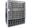
...-slot system contains two slots for Route Processor Modules (RPMs) and eight slots for line cards. 2 Overview The C300 is a high performance switch/router. Figure 2-1. C300 Chassis (Front View) Front Mount Bracket 4-Port Fiber Line Card Fan Tray 0 1 2 3 R0 R1 4 ...SFM Status Master ACTIVE Alarm SFM Status Master ACTIVE Alarm RJ-45 Console RJ-45 Console Compact Flash Compact Flash Reset Reset BLNK 5 BLNK 6 BLNK 7 48-Port Line Card Route Processor Module Line Card Blank AC Power...
...-slot system contains two slots for Route Processor Modules (RPMs) and eight slots for line cards. 2 Overview The C300 is a high performance switch/router. Figure 2-1. C300 Chassis (Front View) Front Mount Bracket 4-Port Fiber Line Card Fan Tray 0 1 2 3 R0 R1 4 ...SFM Status Master ACTIVE Alarm SFM Status Master ACTIVE Alarm RJ-45 Console RJ-45 Console Compact Flash Compact Flash Reset Reset BLNK 5 BLNK 6 BLNK 7 48-Port Line Card Route Processor Module Line Card Blank AC Power...

C300 Hardware Installation Guide
Page 12
... management cables. 7 Install the power supplies. 8 Switch on page 39 12 | Overview www.dell.com | support.dell.com Table 2-1. C300 Component Requirements Component Minimum Backplane (factory installed) 1 Fan tray 1 RPM 1 Line card 1 AC Power Supply 2 DC Power Entry Module 2 Maximum 1 1 2 8 8 8 Field-Replaceable No Yes Yes Yes Yes Yes C300 System Installation Process The Dell Force10 recommended installation process is...
... management cables. 7 Install the power supplies. 8 Switch on page 39 12 | Overview www.dell.com | support.dell.com Table 2-1. C300 Component Requirements Component Minimum Backplane (factory installed) 1 Fan tray 1 RPM 1 Line card 1 AC Power Supply 2 DC Power Entry Module 2 Maximum 1 1 2 8 8 8 Field-Replaceable No Yes Yes Yes Yes Yes C300 System Installation Process The Dell Force10 recommended installation process is...

C300 Hardware Installation Guide
Page 27
... a main disconnect device installed. It is the responsibility of two AC power supplies to enable Power over Ethernet (PoE). Additional power supplies are required to operate, but Dell Force10 recommends a two-plus-one redundancy configuration, so a minimum of the chassis (Figure 7-1). 7 Installing AC Power Supplies The C300 has eight power supply slots at the front-bottom of three...
... a main disconnect device installed. It is the responsibility of two AC power supplies to enable Power over Ethernet (PoE). Additional power supplies are required to operate, but Dell Force10 recommends a two-plus-one redundancy configuration, so a minimum of the chassis (Figure 7-1). 7 Installing AC Power Supplies The C300 has eight power supply slots at the front-bottom of three...

C300 Hardware Installation Guide
Page 29
... limits. Installing the AC Power Supply WARNING: Use only the power cord supplied with the power supply. Table 7-1. AC Power Supply Handle l Switch O Power LED AC Power Receptacle Retaining Pin Threaded Hole Power Supply Retaining Pin fnC0002mp Each AC power supply has one other unit operating in the power supply, it must be ...limits. This LED does not function unless an RPM is functioning properly The unit has failed, possibly due to your C300 system until the power supplies, blank panels, fan tray, RPMs, and line cards have been installed. The unit is installed. Figure 7-2.
... limits. Installing the AC Power Supply WARNING: Use only the power cord supplied with the power supply. Table 7-1. AC Power Supply Handle l Switch O Power LED AC Power Receptacle Retaining Pin Threaded Hole Power Supply Retaining Pin fnC0002mp Each AC power supply has one other unit operating in the power supply, it must be ...limits. This LED does not function unless an RPM is functioning properly The unit has failed, possibly due to your C300 system until the power supplies, blank panels, fan tray, RPMs, and line cards have been installed. The unit is installed. Figure 7-2.


