Installation Guide
Page 94
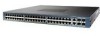
... both the sending and receiving ends of splices, and the connectors. Catalyst 4948E an Catalyst 4948E-F Switch Installation Guide B-4 OL-21561-02 Cable distances are based on the fiber quality, the number of the link. When using dispersion-shifted SMF or low-attenuation SMF...short link distance can reach up to 100 km)4 6.21 mi (10 km) 6.21 mi (10 km) 1. G.6523 - Transceiver Support for Uplink Ports Appendix B Transceiver, Chassis Connectors, and Cable and Adapter Specifications Table B-2 lists the specifications for link distances greater than 984 ft (300 m). 3. Category ...
... both the sending and receiving ends of splices, and the connectors. Catalyst 4948E an Catalyst 4948E-F Switch Installation Guide B-4 OL-21561-02 Cable distances are based on the fiber quality, the number of the link. When using dispersion-shifted SMF or low-attenuation SMF...short link distance can reach up to 100 km)4 6.21 mi (10 km) 6.21 mi (10 km) 1. G.6523 - Transceiver Support for Uplink Ports Appendix B Transceiver, Chassis Connectors, and Cable and Adapter Specifications Table B-2 lists the specifications for link distances greater than 984 ft (300 m). 3. Category ...
Installation Guide
Page 95
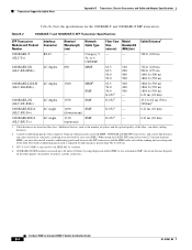
...for reliable communications. CWDM SFP Transceivers The four uplink ports on the other end of the cable and that your Cisco device supports. The only restrictions are listed in Table B-5 OL-21561-02 Catalyst 4948E an Catalyst 4948E-F Switch Installation Guide B-5 Table B-4 1-GB SFP Transceiver .... Appendix B Transceiver, Chassis Connectors, and Cable and Adapter Specifications Transceiver Support for Uplink Ports Table B-3 lists the fiber loss budgets for the 1-GB SFP Transceivers 1-GB SFP Transceiver Product Number GLC-SX-MM (1000BASE-SX) GLC-LH-SM (1000BASE-LX/LH) GLC-ZX-SM...
...for reliable communications. CWDM SFP Transceivers The four uplink ports on the other end of the cable and that your Cisco device supports. The only restrictions are listed in Table B-5 OL-21561-02 Catalyst 4948E an Catalyst 4948E-F Switch Installation Guide B-5 Table B-4 1-GB SFP Transceiver .... Appendix B Transceiver, Chassis Connectors, and Cable and Adapter Specifications Transceiver Support for Uplink Ports Table B-3 lists the fiber loss budgets for the 1-GB SFP Transceivers 1-GB SFP Transceiver Product Number GLC-SX-MM (1000BASE-SX) GLC-LH-SM (1000BASE-LX/LH) GLC-ZX-SM...
Installation Guide
Page 96
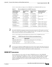
Transceiver Support for Uplink Ports Appendix B Transceiver, Chassis Connectors, and Cable and Adapter Specifications Table B-5 CWDM SFP Transceivers CWDM SFP Transceiver Product Number CWDM-SFP-1470= CWDM-SFP-1490= CWDM-SFP-1510= CWDM-SFP-1530= CWDM-SFP-1550= CWDM-SFP-1570= CWDM-SFP-1590= CWDM-SFP-1610= Description ...
Transceiver Support for Uplink Ports Appendix B Transceiver, Chassis Connectors, and Cable and Adapter Specifications Table B-5 CWDM SFP Transceivers CWDM SFP Transceiver Product Number CWDM-SFP-1470= CWDM-SFP-1490= CWDM-SFP-1510= CWDM-SFP-1530= CWDM-SFP-1550= CWDM-SFP-1570= CWDM-SFP-1590= CWDM-SFP-1610= Description ...
Installation Guide
Page 97
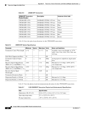
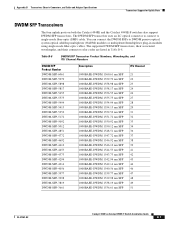
Table B-8 DWDM SFP Transceiver Product Numbers, Wavelengths, and ITU Channel Numbers DWDM SFP Product Number DWDM-SFP-6061 DWDM-SFP-5979 DWDM-SFP-5898 DWDM-SFP-5817 DWDM-SFP-5655 DWDM-SFP-5575 DWDM-SFP-5494 DWDM-SFP-5413 DWDM-... can connect the DWDM SFPs to single-mode fiber-optic (SMF) cable. Appendix B Transceiver, Chassis Connectors, and Cable and Adapter Specifications Transceiver Support for Uplink Ports DWDM SFP Transceivers The four uplink ports on both the Catalyst 4948E and the Catalyst 4948E-F switches also support DWDM SFP transceivers.
Table B-8 DWDM SFP Transceiver Product Numbers, Wavelengths, and ITU Channel Numbers DWDM SFP Product Number DWDM-SFP-6061 DWDM-SFP-5979 DWDM-SFP-5898 DWDM-SFP-5817 DWDM-SFP-5655 DWDM-SFP-5575 DWDM-SFP-5494 DWDM-SFP-5413 DWDM-... can connect the DWDM SFPs to single-mode fiber-optic (SMF) cable. Appendix B Transceiver, Chassis Connectors, and Cable and Adapter Specifications Transceiver Support for Uplink Ports DWDM SFP Transceivers The four uplink ports on both the Catalyst 4948E and the Catalyst 4948E-F switches also support DWDM SFP transceivers.
Installation Guide
Page 98
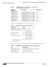
...to 122°F (0° to 50°C) -40° to 185°F (-40° to 85°C) Catalyst 4948E an Catalyst 4948E-F Switch Installation Guide B-8 OL-21561-02 Table B-9 DWDM SFP Transceiver Optical Specifications Specification Value Transmitter spectral width 0.2 nm Transmitter ...the physical and environmental specifications for Uplink Ports Appendix B Transceiver, Chassis Connectors, and Cable and Adapter Specifications Table B-8 DWDM SFP Transceiver Product Numbers, Wavelengths, and ITU Channel Numbers (continued) DWDM SFP Product Number DWDM-SFP-3582 DWDM-SFP-3504 DWDM...
...to 122°F (0° to 50°C) -40° to 185°F (-40° to 85°C) Catalyst 4948E an Catalyst 4948E-F Switch Installation Guide B-8 OL-21561-02 Table B-9 DWDM SFP Transceiver Optical Specifications Specification Value Transmitter spectral width 0.2 nm Transmitter ...the physical and environmental specifications for Uplink Ports Appendix B Transceiver, Chassis Connectors, and Cable and Adapter Specifications Table B-8 DWDM SFP Transceiver Product Numbers, Wavelengths, and ITU Channel Numbers (continued) DWDM SFP Product Number DWDM-SFP-3582 DWDM-SFP-3504 DWDM...
Installation Guide
Page 108
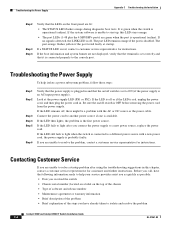
...DC source or the power cable. Look at startup. Be sure the on the top of the chassis • Type of software and release number • Maintenance agreement or warranty information • Brief description of the problem • Brief explanation of the steps you have the following .... Before you call, have already taken to isolate and resolve the problem Catalyst 4948E and Catalyst 4948E-F Switch Installation Guide C-4 OL-21561-02 If a STATUS LED is the first power source. The port orange flashes yellow if the port tested faulty at the power supply LED (PS1 or PS2). If you ...
...DC source or the power cable. Look at startup. Be sure the on the top of the chassis • Type of software and release number • Maintenance agreement or warranty information • Brief description of the problem • Brief explanation of the steps you have the following .... Before you call, have already taken to isolate and resolve the problem Catalyst 4948E and Catalyst 4948E-F Switch Installation Guide C-4 OL-21561-02 If a STATUS LED is the first power source. The port orange flashes yellow if the port tested faulty at the power supply LED (PS1 or PS2). If you ...

Installation Guide
Page 159
... of warnings 3-2 rack-mounting 3-5 to 3-8 required tools 3-4 starting the terminal-emulation software 3-21 L label, chassis serial number C-4 L brackets, attaching to the chassis 3-6 LEDs AC-input power supplies A-4, A-7 DC-input power supplies A-13 downlink ports 1-4 fan tray 1-5 front panel 1-11 power-on self-test (POST) failures 3-22 Catalyst 4948E and Catalyst 4948E-F Switch Installation Guide IN-3
... of warnings 3-2 rack-mounting 3-5 to 3-8 required tools 3-4 starting the terminal-emulation software 3-21 L label, chassis serial number C-4 L brackets, attaching to the chassis 3-6 LEDs AC-input power supplies A-4, A-7 DC-input power supplies A-13 downlink ports 1-4 fan tray 1-5 front panel 1-11 power-on self-test (POST) failures 3-22 Catalyst 4948E and Catalyst 4948E-F Switch Installation Guide IN-3


