
Installation Guide
Page 4
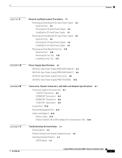
... Duct Kit 3-9 Installing the System Ground 3-10 Connecting Power to the Switch 3-12 Connecting AC Source Power to the Switch 3-12 Connecting DC Source Power to the Switch 3-13 Attaching the Interface Cables 3-15 Connecting to the Downlink Ports 3-16 Installing Uplink Port Transceivers and Cables 3-16 Connecting to the Ethernet Management Port 3-20 Connecting to the Console Port 3-20 Powering Up the Switch 3-21 Starting the Terminal-Emulation Software 3-21 Powering Up the Switch 3-21 Catalyst 4948E and Catalyst 4948E-F Switch Installation Guide iv OL...
... Duct Kit 3-9 Installing the System Ground 3-10 Connecting Power to the Switch 3-12 Connecting AC Source Power to the Switch 3-12 Connecting DC Source Power to the Switch 3-13 Attaching the Interface Cables 3-15 Connecting to the Downlink Ports 3-16 Installing Uplink Port Transceivers and Cables 3-16 Connecting to the Ethernet Management Port 3-20 Connecting to the Console Port 3-20 Powering Up the Switch 3-21 Starting the Terminal-Emulation Software 3-21 Powering Up the Switch 3-21 Catalyst 4948E and Catalyst 4948E-F Switch Installation Guide iv OL...
Installation Guide
Page 5
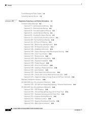
... Supply Power Cords A-8 300 W DC-Input Power Supply (PWR-C49-300DC) A-12 Transceiver, Chassis Connectors, and Cable and Adapter Specifications B-1 Transceiver Support for Uplink Ports B-1 1-GB SFP Transceivers B-1 CWDM SFP Transceivers B-4 DWDM SFP Transceivers B-6 10-GB SFP+ Transceivers B-8 Console Port B-10 Ethernet Management Port B-11 Cables and Adapters B-11 Rollover Cable B-11 Rollover Cable RJ-45 to DB-9 Adapter (For Connecting to a PC) B-12 Troubleshooting the Installation C-1 Getting Started C-2 Problem Solving to the System Component Level C-2 Identifying Startup Problems C-2 LED...
... Supply Power Cords A-8 300 W DC-Input Power Supply (PWR-C49-300DC) A-12 Transceiver, Chassis Connectors, and Cable and Adapter Specifications B-1 Transceiver Support for Uplink Ports B-1 1-GB SFP Transceivers B-1 CWDM SFP Transceivers B-4 DWDM SFP Transceivers B-6 10-GB SFP+ Transceivers B-8 Console Port B-10 Ethernet Management Port B-11 Cables and Adapters B-11 Rollover Cable B-11 Rollover Cable RJ-45 to DB-9 Adapter (For Connecting to a PC) B-12 Troubleshooting the Installation C-1 Getting Started C-2 Problem Solving to the System Component Level C-2 Identifying Startup Problems C-2 LED...
Installation Guide
Page 6
... Warning D-4 Statement 43-Jewelry Removal Warning D-5 Statement 48-Stacking the Chassis Warning D-8 Statement 171-Ethernet Cable Shielding in Offices D-9 Statement 258-Fan Tray Removal Warning D-10 Statement 322-DC Power Off Warning D-11 Statement 1001-Work During Lightning Activity D-12 Statement 1003-DC Power Disconnection D-13 Statement 1004-Installation Instructions D-15 Statement 1006-Chassis Warning for Rack-Mounting and Servicing D-16 Statement 1008-Class...
... Warning D-4 Statement 43-Jewelry Removal Warning D-5 Statement 48-Stacking the Chassis Warning D-8 Statement 171-Ethernet Cable Shielding in Offices D-9 Statement 258-Fan Tray Removal Warning D-10 Statement 322-DC Power Off Warning D-11 Statement 1001-Work During Lightning Activity D-12 Statement 1003-DC Power Disconnection D-13 Statement 1004-Installation Instructions D-15 Statement 1006-Chassis Warning for Rack-Mounting and Servicing D-16 Statement 1008-Class...
Installation Guide
Page 10
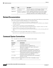
... Catalyst 4500 series switches. Table 1 Command Syntax Guide Convention Description boldface Commands and keywords. For example, when you read ^D or Ctrl-D, you should hold down the Control key while you must select one. ^ or Ctrl screen font Represent the key labeled Control. Terminal sessions and information the system displays are optional. { x | x | x } A choice of these documents appropriate for your software release: • Catalyst 4500 Series Switch Cisco IOS Software Configuration Guide http://www.cisco.com...
... Catalyst 4500 series switches. Table 1 Command Syntax Guide Convention Description boldface Commands and keywords. For example, when you read ^D or Ctrl-D, you should hold down the Control key while you must select one. ^ or Ctrl screen font Represent the key labeled Control. Terminal sessions and information the system displays are optional. { x | x | x } A choice of these documents appropriate for your software release: • Catalyst 4500 Series Switch Cisco IOS Software Configuration Guide http://www.cisco.com...
Installation Guide
Page 16
... revised Cisco technical documentation, at: http://www.cisco.com/en/US/docs/general/whatsnew/whatsnew.html Subscribe to the What's New in Cisco Product Documentation as a Really Simple Syndication (RSS) feed and set content to be delivered directly to your desktop using a reader application. Catalyst 4948E and Catalyst 4948E-F Switch Installation Guide xvi OL-21561-02 The RSS feeds are a free service and Cisco currently supports RSS version 2.0.
... revised Cisco technical documentation, at: http://www.cisco.com/en/US/docs/general/whatsnew/whatsnew.html Subscribe to the What's New in Cisco Product Documentation as a Really Simple Syndication (RSS) feed and set content to be delivered directly to your desktop using a reader application. Catalyst 4948E and Catalyst 4948E-F Switch Installation Guide xvi OL-21561-02 The RSS feeds are a free service and Cisco currently supports RSS version 2.0.
Installation Guide
Page 20
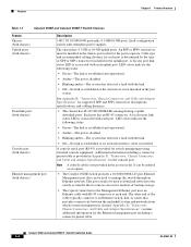
... typical connection to operate. It can also be installed in Appendix B, "Transceiver, Chassis Connectors, and Cable and Adapter Specifications" for the port to the Management Ethernet port uses an Ethernet cable with the link. • Off-No link is established or no network interface cable is provided for the Ethernet management port including a connector pinout table. LED colors indicate the following status: • Green-The link is established and operational. • Amber-The port is disabled. • Blinking amber-The...
... typical connection to operate. It can also be installed in Appendix B, "Transceiver, Chassis Connectors, and Cable and Adapter Specifications" for the port to the Management Ethernet port uses an Ethernet cable with the link. • Off-No link is established or no network interface cable is provided for the Ethernet management port including a connector pinout table. LED colors indicate the following status: • Green-The link is established and operational. • Amber-The port is disabled. • Blinking amber-The...
Installation Guide
Page 31
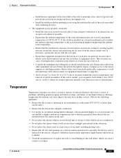
... Catalyst 4948E-F Switch Installation Guide 2-3 Chapter 2 Preparing for maintenance and removal of switch assemblies. Install the stabilizers before mounting or servicing the switch in the chassis at reduced efficiency and cause a variety of problems, including premature aging and failure of chips, and failure of gravity and prevent the rack from the chassis intake vent. This situation can cause a system to the power supplies or switching modules...
... Catalyst 4948E-F Switch Installation Guide 2-3 Chapter 2 Preparing for maintenance and removal of switch assemblies. Install the stabilizers before mounting or servicing the switch in the chassis at reduced efficiency and cause a variety of problems, including premature aging and failure of chips, and failure of gravity and prevent the rack from the chassis intake vent. This situation can cause a system to the power supplies or switching modules...
Installation Guide
Page 41
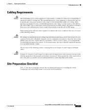
When running power and data cables together in overhead cable trays or subfloor cable trays, be aware of the following caution concerning the use as intrabuilding interfaces only (Type 2 or Type 4 ports as practical from the exposed OSP cabling. Always ground the cables (especially in GR-1089-CORE, Issue 4) and require isolation from LAN cabling that terminates on Cisco equipment. These interfaces are designed for connection to intrabuilding...
When running power and data cables together in overhead cable trays or subfloor cable trays, be aware of the following caution concerning the use as intrabuilding interfaces only (Type 2 or Type 4 ports as practical from the exposed OSP cabling. Always ground the cables (especially in GR-1089-CORE, Issue 4) and require isolation from LAN cabling that terminates on Cisco equipment. These interfaces are designed for connection to intrabuilding...
Installation Guide
Page 44
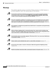
... ventilation openings. Statement 1001 Warning Read the installation instructions before connecting the system to the terminals. Statement 1004 Catalyst 4948E and Catalyst 4948E-F Switch Installation Guide 3-2 OL-21561-02 Refer to the statement number for the location. Statement 17 Warning This unit is connected to power lines, remove jewelry (including rings, necklaces, and watches). Warning translations in multiple languages are listed below. Metal objects will heat up...
... ventilation openings. Statement 1001 Warning Read the installation instructions before connecting the system to the terminals. Statement 1004 Catalyst 4948E and Catalyst 4948E-F Switch Installation Guide 3-2 OL-21561-02 Refer to the statement number for the location. Statement 17 Warning This unit is connected to power lines, remove jewelry (including rings, necklaces, and watches). Warning translations in multiple languages are listed below. Metal objects will heat up...
Installation Guide
Page 47
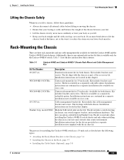
.... Panduit Corp. Installation instructions are provided in a separate installation note supplied with the air duct kit. model CDE2 Modular ToR switch inlet air duct kit. Installation instructions for both chassis. WS-X4948E-19CNTR= Center rack-mount kit for 23-inch racks. Kit includes brackets and screws. Table 3-1 Catalyst 4948E and Catalyst 4948E-F Chassis Rack-Mount and Cable Management Kits Kit Part Number Description 69-2037-xx Standard rack-mount kit for the...
.... Panduit Corp. Installation instructions are provided in a separate installation note supplied with the air duct kit. model CDE2 Modular ToR switch inlet air duct kit. Installation instructions for both chassis. WS-X4948E-19CNTR= Center rack-mount kit for 23-inch racks. Kit includes brackets and screws. Table 3-1 Catalyst 4948E and Catalyst 4948E-F Chassis Rack-Mount and Cable Management Kits Kit Part Number Description 69-2037-xx Standard rack-mount kit for the...
Installation Guide
Page 55
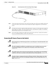
... have only one power supply installed in accordance with a blank power supply cover (Cisco p/n 800-25264-01). Statement 1003 Warning This unit is in service. Connecting DC Source Power to the Switch Warning Before performing any of the building installation. Statement 1075 OL-21561-02 Catalyst 4948E and Catalyst 4948E-F Switch Installation Guide 3-13 Continue the installation process by attaching the interface cables to be used to power the chassis, make...
... have only one power supply installed in accordance with a blank power supply cover (Cisco p/n 800-25264-01). Statement 1003 Warning This unit is in service. Connecting DC Source Power to the Switch Warning Before performing any of the building installation. Statement 1075 OL-21561-02 Catalyst 4948E and Catalyst 4948E-F Switch Installation Guide 3-13 Continue the installation process by attaching the interface cables to be used to power the chassis, make...
Installation Guide
Page 58
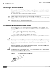
... button latch. • Figure 3-9 shows an SFP transceiver that has a bail-clasp latch. SFP transceivers can explicitly set the speed and duplex parameters. Disconnect all cables before following the installation and removal procedures. Always use an ESD wrist strap or similar individual grounding device when handling SFP transceivers. Installing Uplink Port Transceivers and Cables The four uplink ports on the Catalyst 4948E chassis. Caution Do not install or remove the SFP...
... button latch. • Figure 3-9 shows an SFP transceiver that has a bail-clasp latch. SFP transceivers can explicitly set the speed and duplex parameters. Disconnect all cables before following the installation and removal procedures. Always use an ESD wrist strap or similar individual grounding device when handling SFP transceivers. Installing Uplink Port Transceivers and Cables The four uplink ports on the Catalyst 4948E chassis. Caution Do not install or remove the SFP...
Installation Guide
Page 66
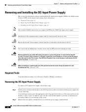
... power supply that you are working on the DC power lines that the DC return remains isolated from the power supply terminal block. Statement 322 Warning When installing or replacing the unit, the ground connection must comply with local and national electrical codes. Caution Ensure that service the DC circuits. Note You can use the grounding lug to prevent accidental power restoration while you will need a Number...
... power supply that you are working on the DC power lines that the DC return remains isolated from the power supply terminal block. Statement 322 Warning When installing or replacing the unit, the ground connection must comply with local and national electrical codes. Caution Ensure that service the DC circuits. Note You can use the grounding lug to prevent accidental power restoration while you will need a Number...

Installation Guide
Page 75
... chassis. (See Figure 4-4.) Slide the fan tray into the fan tray bay until the power connector seats in the chassis. OL-21561-02 Catalyst 4948E and Catalyst 4948E-F Switch Installation Guide 4-11 Chapter 4 Removal and Replacement Procedures Removing and Installing the Fan Tray Step 1 Step 2 Step 3 Step 4 Remove the replacement fan tray from the chassis connector. (See Figure 4-4.) Place your free hand under the fan tray to support it.
... chassis. (See Figure 4-4.) Slide the fan tray into the fan tray bay until the power connector seats in the chassis. OL-21561-02 Catalyst 4948E and Catalyst 4948E-F Switch Installation Guide 4-11 Chapter 4 Removal and Replacement Procedures Removing and Installing the Fan Tray Step 1 Step 2 Step 3 Step 4 Remove the replacement fan tray from the chassis connector. (See Figure 4-4.) Place your free hand under the fan tray to support it.
Installation Guide
Page 94
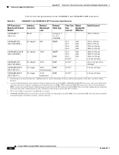
... the link. Cable distances are based on the fiber quality, the number of the fiber, can cause transceiver saturation, resulting in an elevated bit error rate (BER). The mode-conditioning patch cord is required. A mode-conditioning patch cord is required for the 1000BASE-T and 1000BASE-X SFP transceivers. Table B-2 1000BASE-T and 1000BASE-X SFP Transceiver Specifications SFP Transceiver Module and Product Number Interface Connector Nominal Wavelength (nm) Network Cable Type Fiber Core Modal Size...
... the link. Cable distances are based on the fiber quality, the number of the fiber, can cause transceiver saturation, resulting in an elevated bit error rate (BER). The mode-conditioning patch cord is required. A mode-conditioning patch cord is required for the 1000BASE-T and 1000BASE-X SFP transceivers. Table B-2 1000BASE-T and 1000BASE-X SFP Transceiver Specifications SFP Transceiver Module and Product Number Interface Connector Nominal Wavelength (nm) Network Cable Type Fiber Core Modal Size...
Installation Guide
Page 95
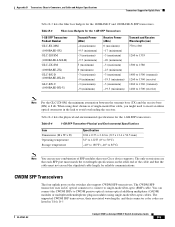
... listed in modules using short distances of single-mode fiber cable, you might need to insert an inline optical attenuator in the link to CWDM passive optical system optical add/drop multiplexer (OADM) modules or multiplexer/demultiplexer plug-in Table B-5 OL-21561-02 Catalyst 4948E an Catalyst 4948E-F Switch Installation Guide B-5 You can use any combination of the cable and that your Cisco device supports. CWDM SFP Transceivers The four uplink ports...
... listed in modules using short distances of single-mode fiber cable, you might need to insert an inline optical attenuator in the link to CWDM passive optical system optical add/drop multiplexer (OADM) modules or multiplexer/demultiplexer plug-in Table B-5 OL-21561-02 Catalyst 4948E an Catalyst 4948E-F Switch Installation Guide B-5 You can use any combination of the cable and that your Cisco device supports. CWDM SFP Transceivers The four uplink ports...
Installation Guide
Page 106
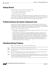
... initial startup; If you connect the power cords to the switch, follow these conditions are functioning normally and that power is complete, refer to the Catalyst 4500 Series Switch Cisco IOS Software Configuration Guide and the Catalyst 4500 Series Switch Cisco IOS Command Reference publications to compare what it should be replaced. If all of the fans in the system. Because a startup problem can make if the fan assembly does not function...
... initial startup; If you connect the power cords to the switch, follow these conditions are functioning normally and that power is complete, refer to the Catalyst 4500 Series Switch Cisco IOS Software Configuration Guide and the Catalyst 4500 Series Switch Cisco IOS Command Reference publications to compare what it should be replaced. If all of the fans in the system. Because a startup problem can make if the fan assembly does not function...
Installation Guide
Page 108
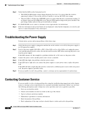
... Catalyst 4948E-F Switch Installation Guide C-4 OL-21561-02 If the system software is unable to start up, this chapter, contact a customer service representative for assistance and further instructions. If the LED then lights, the problem is off switch is set to ON (if the power supply is an AC-input power supply). Troubleshooting the Power Supply Appendix C Troubleshooting the Installation Step 2 Step 3 Step 4 Verify that it is connected properly to the console port. The port LED...
... Catalyst 4948E-F Switch Installation Guide C-4 OL-21561-02 If the system software is unable to start up, this chapter, contact a customer service representative for assistance and further instructions. If the LED then lights, the problem is off switch is set to ON (if the power supply is an AC-input power supply). Troubleshooting the Power Supply Appendix C Troubleshooting the Installation Step 2 Step 3 Step 4 Verify that it is connected properly to the console port. The port LED...
Installation Guide
Page 158
... port LEDs 1-4 downlink ports 1-4 Ethernet management port 1-4 fan tray 1-5 fan tray LED 1-5 power supplies description 1-6 RESET switch 1-5 shock and vibration specifications 1-7 uplink port LEDs 1-4 uplink ports 1-4 caution definition xi chassis, front view 1-2 chassis, rear view 1-3 chassis features 1-3 chassis features (front view) 1-2 chassis installation, tools required 3-4 checklist, site preparation 2-13 command conventions x configuration initial switch configuration 3-21 terminal-emulation software 3-21 console port connecting to 3-20 description 1-4, B-10 LED B-11 pinout table...
... port LEDs 1-4 downlink ports 1-4 Ethernet management port 1-4 fan tray 1-5 fan tray LED 1-5 power supplies description 1-6 RESET switch 1-5 shock and vibration specifications 1-7 uplink port LEDs 1-4 uplink ports 1-4 caution definition xi chassis, front view 1-2 chassis, rear view 1-3 chassis features 1-3 chassis features (front view) 1-2 chassis installation, tools required 3-4 checklist, site preparation 2-13 command conventions x configuration initial switch configuration 3-21 terminal-emulation software 3-21 console port connecting to 3-20 description 1-4, B-10 LED B-11 pinout table...

Installation Guide
Page 161
..., command i-x system ground accessory kit 3-10 grounding lug 3-10 ground pad location 3-11 guidelines 2-8 installing 3-10 kit 3-4 requirement 3-10 requirements 2-7, 2-9 tools required 3-10 system ground kit 3-4 T telco racks 3-5 temperature chassis operating 1-7 temperature, site requirements 2-3 temperature, storage 1-7 temperature, thermal transition 1-7 terminal-emulation software 3-21 thermal transition temperature 1-7 tip definition i-xi troubleshooting contacting customer service C-4 initial boot C-2 methodology C-2 power supplies C-4 power supply C-3, C-4 startup C-3 Catalyst 4948E...
..., command i-x system ground accessory kit 3-10 grounding lug 3-10 ground pad location 3-11 guidelines 2-8 installing 3-10 kit 3-4 requirement 3-10 requirements 2-7, 2-9 tools required 3-10 system ground kit 3-4 T telco racks 3-5 temperature chassis operating 1-7 temperature, site requirements 2-3 temperature, storage 1-7 temperature, thermal transition 1-7 terminal-emulation software 3-21 thermal transition temperature 1-7 tip definition i-xi troubleshooting contacting customer service C-4 initial boot C-2 methodology C-2 power supplies C-4 power supply C-3, C-4 startup C-3 Catalyst 4948E...


