Software Guide
Page 17
...01 Configuring a Login Banner 27-4 Clearing the Login Banner 27-5 Enabling or Disabling the "Cisco Systems Console" Telnet Login Banner 27-5 Defining and Using Command Aliases 27-6 Defining and ...Power Management 28-1 Understanding How Power Management Works on the Catalyst 4500 Series Switches 28-1 Power Management Overview 28-2 Understanding Power Management Modes 28-2 Available Power for Power Supplies 28-4 Power Management Limitations 28-4 1400 W DC Power Supply Guidelines and Restrictions 28-5 Understanding How Power Management Works on the Catalyst 4006 Switch 28-6 Understanding Power...
...01 Configuring a Login Banner 27-4 Clearing the Login Banner 27-5 Enabling or Disabling the "Cisco Systems Console" Telnet Login Banner 27-5 Defining and Using Command Aliases 27-6 Defining and ...Power Management 28-1 Understanding How Power Management Works on the Catalyst 4500 Series Switches 28-1 Power Management Overview 28-2 Understanding Power Management Modes 28-2 Available Power for Power Supplies 28-4 Power Management Limitations 28-4 1400 W DC Power Supply Guidelines and Restrictions 28-5 Understanding How Power Management Works on the Catalyst 4006 Switch 28-6 Understanding Power...
Software Guide
Page 31
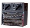
... the Catalyst 4000 series switches. Table 1-1 Catalyst 4000 Series and Catalyst 4500 Series Switches Product Number Catalyst 4000 Series WS-C4003 WS-C4006 Chassis Description Catalyst 4003 • Modular 3-slot chassis • Optional redundant power supplies Catalyst 4006 • Modular 6-slot chassis • 30-Gbps backplane • Two power supplies with optional third power supply 78-15486-01 Catalyst 4500 Series, Catalyst 2948G, Catalyst 2980G Switches Software Configuration...
... the Catalyst 4000 series switches. Table 1-1 Catalyst 4000 Series and Catalyst 4500 Series Switches Product Number Catalyst 4000 Series WS-C4003 WS-C4006 Chassis Description Catalyst 4003 • Modular 3-slot chassis • Optional redundant power supplies Catalyst 4006 • Modular 6-slot chassis • 30-Gbps backplane • Two power supplies with optional third power supply 78-15486-01 Catalyst 4500 Series, Catalyst 2948G, Catalyst 2980G Switches Software Configuration...
Software Guide
Page 32
... full duplex backplane • Optional redundant power supplies Catalyst 4506 • Modular 6-slot chassis • 64 Gbps full duplex • Optional redundant power supplies Catalyst 2948G Switch Note For installation information and a complete description of the Catalyst 2948G switch hardware, refer to the Catalyst 2948G and 2980G Installation Guide. Table 1-2 describes the Catalyst 2948G switch. Table 1-2 Catalyst 2948G Switch Product Number WS-C2948G Chassis Description...
... full duplex backplane • Optional redundant power supplies Catalyst 4506 • Modular 6-slot chassis • 64 Gbps full duplex • Optional redundant power supplies Catalyst 2948G Switch Note For installation information and a complete description of the Catalyst 2948G switch hardware, refer to the Catalyst 2948G and 2980G Installation Guide. Table 1-2 describes the Catalyst 2948G switch. Table 1-2 Catalyst 2948G Switch Product Number WS-C2948G Chassis Description...

Software Guide
Page 33
Table 1-3 describes the Catalyst 2980G switch. Table 1-3 Catalyst 2980G Switch Product Number WS-C2980G-A Chassis Description Catalyst 2980G • Fixed-configuration switch • 12-Gbps backplane • Optional redundant power supplies • Two 1000BASE-X (GBIC) Gigabit Ethernet ports • 80 10/100BASE-TX Fast Ethernet ports Supervisor Engine Software The supervisor engine software is factory installed ...
Table 1-3 describes the Catalyst 2980G switch. Table 1-3 Catalyst 2980G Switch Product Number WS-C2980G-A Chassis Description Catalyst 2980G • Fixed-configuration switch • 12-Gbps backplane • Optional redundant power supplies • Two 1000BASE-X (GBIC) Gigabit Ethernet ports • 80 10/100BASE-TX Fast Ethernet ports Supervisor Engine Software The supervisor engine software is factory installed ...
Software Guide
Page 373
...to an NMS message. Catalyst enterprise LAN switches are spanning tree topology changes - When a trap condition occurs, the SNMP agent sends an SNMP trap message to any NMS that is specified as embedded passwords: - When there are exceeded - When power supply errors occur • ... software (see Chapter 25, "Configuring RMON") • RMON and RMON2 on an external SwitchProbe device 78-15486-01 Catalyst 4500 Series, Catalyst 2948G, Catalyst 2980G Switches Software Configuration Guide-Release 8.1 24-5 When there are managed devices that value. • Setting a MIB variable-This ...
...to an NMS message. Catalyst enterprise LAN switches are spanning tree topology changes - When a trap condition occurs, the SNMP agent sends an SNMP trap message to any NMS that is specified as embedded passwords: - When there are exceeded - When power supply errors occur • ... software (see Chapter 25, "Configuring RMON") • RMON and RMON2 on an external SwitchProbe device 78-15486-01 Catalyst 4500 Series, Catalyst 2948G, Catalyst 2980G Switches Software Configuration Guide-Release 8.1 24-5 When there are managed devices that value. • Setting a MIB variable-This ...

Software Guide
Page 412
...Creating a Login Banner You can configure the switch to the switch. Setting the System Clock Chapter 27 Administering the Switch disable 9600 0% 0% Wed Apr 24 2002, 15:46:01 Power Capacity of the Chassis:2 supplies WARNING:Power supplies of different values have been inserted System Name...clock and display the current date and time: Console> (enable) set banner motd c message_of_the_day c - 27-4 Catalyst 4500 Series, Catalyst 2948G, Catalyst 2980G Switches Software Configuration Guide-Release 8.1 78-15486-01 Display the current date and time. After entering the ending delimiter, ...
...Creating a Login Banner You can configure the switch to the switch. Setting the System Clock Chapter 27 Administering the Switch disable 9600 0% 0% Wed Apr 24 2002, 15:46:01 Power Capacity of the Chassis:2 supplies WARNING:Power supplies of different values have been inserted System Name...clock and display the current date and time: Console> (enable) set banner motd c message_of_the_day c - 27-4 Catalyst 4500 Series, Catalyst 2948G, Catalyst 2980G Switches Software Configuration Guide-Release 8.1 78-15486-01 Display the current date and time. After entering the ending delimiter, ...

Software Guide
Page 422
... damage your switch, the switch uses the power supply in power supply bay 1 (PS1) and ignores the power supply in your switch. If the primary power supply fails, the second power supply supports the switch without disrupting the network. Understanding Power Management Modes Catalyst 4500 series switches support these two power management modes: • Redundant mode-Uses one or more power than a single power supply provides, use power supplies with any other power supply, even...
... damage your switch, the switch uses the power supply in power supply bay 1 (PS1) and ignores the power supply in your switch. If the primary power supply fails, the second power supply supports the switch without disrupting the network. Understanding Power Management Modes Catalyst 4500 series switches support these two power management modes: • Redundant mode-Uses one or more power than a single power supply provides, use power supplies with any other power supply, even...

Software Guide
Page 423
The power supplies have power redundancy. • When using variable power supplies, choose a power supply that supplies enough power so that can seriously damage your switch to redundant mode and only one power supply. Chapter 28 Power Management Understanding How Power Management Works on the Catalyst 4500 Series Switches Redundant Mode Guidelines This section describes the guidelines for using variable power supplies, choose a power supply that supplies enough power so that the chassis...
The power supplies have power redundancy. • When using variable power supplies, choose a power supply that supplies enough power so that can seriously damage your switch to redundant mode and only one power supply. Chapter 28 Power Management Understanding How Power Management Works on the Catalyst 4500 Series Switches Redundant Mode Guidelines This section describes the guidelines for using variable power supplies, choose a power supply that supplies enough power so that the chassis...

Software Guide
Page 424
... Series Switches Chapter 28 Power Management Available Power for Power Supplies Table 28-1 lists the power that is provided by the power supplies. • If you insert a single power supply into the switch and then set the power requirements for the installed modules to exceed the power that is provided by the power supplies for the Catalyst 4500 series switches. The chassis power includes power for the Catalyst 4500 series switches...
... Series Switches Chapter 28 Power Management Available Power for Power Supplies Table 28-1 lists the power that is provided by the power supplies. • If you insert a single power supply into the switch and then set the power requirements for the installed modules to exceed the power that is provided by the power supplies for the Catalyst 4500 series switches. The chassis power includes power for the Catalyst 4500 series switches...

Software Guide
Page 425
... is working properly. 78-15486-01 Catalyst 4500 Series, Catalyst 2948G, Catalyst 2980G Switches Software Configuration Guide-Release 8.1 28-5 Chapter 28 Power Management Understanding How Power Management Works on the Catalyst 4500 Series Switches • Combined mode requires that you set the DC input power. Note A module in your power supply for inline power. The inline power is plugged into reset mode and...
... is working properly. 78-15486-01 Catalyst 4500 Series, Catalyst 2948G, Catalyst 2980G Switches Software Configuration Guide-Release 8.1 28-5 Chapter 28 Power Management Understanding How Power Management Works on the Catalyst 4500 Series Switches • Combined mode requires that you set the DC input power. Note A module in your power supply for inline power. The inline power is plugged into reset mode and...

Software Guide
Page 426
... chassis empty. The power management feature for the Catalyst 4000 series switches support a limited module configuration on power management for the Catalyst 4006 switch. If you to three power supplies. some switch configurations require more power than the power that consume less power, and the total module power usage does not exceed the absolute maximum power usage for the Catalyst 4006 switch have the same wattage...
... chassis empty. The power management feature for the Catalyst 4000 series switches support a limited module configuration on power management for the Catalyst 4006 switch. If you to three power supplies. some switch configurations require more power than the power that consume less power, and the total module power usage does not exceed the absolute maximum power usage for the Catalyst 4006 switch have the same wattage...

Software Guide
Page 427
... configuration by installing a third power supply in the chassis (at boot up the power that require more power than the single power supply provides, the switch places the newly inserted module into reset mode. 78-15486-01 Catalyst 4500 Series, Catalyst 2948G, Catalyst 2980G Switches Software Configuration Guide-Release 8.1 28-7 Two 650 W power supplies supply only 750 W; If you power down a chassis that require more...
... configuration by installing a third power supply in the chassis (at boot up the power that require more power than the single power supply provides, the switch places the newly inserted module into reset mode. 78-15486-01 Catalyst 4500 Series, Catalyst 2948G, Catalyst 2980G Switches Software Configuration Guide-Release 8.1 28-7 Two 650 W power supplies supply only 750 W; If you power down a chassis that require more...

Software Guide
Page 428
... to stabilize the system.You can use a 400 W power supply and a 650 W power supply in reset mode still consume some power. Understanding How Power Management Works on the Catalyst 4006 Switch Chapter 28 Power Management These scenarios initiate the five-minute evaluation countdown timer. If the power requirement of modules that the switch can either remove the extra modules or change...
... to stabilize the system.You can use a 400 W power supply and a 650 W power supply in reset mode still consume some power. Understanding How Power Management Works on the Catalyst 4006 Switch Chapter 28 Power Management These scenarios initiate the five-minute evaluation countdown timer. If the power requirement of modules that the switch can either remove the extra modules or change...

Software Guide
Page 431
... spanning tree topology does not change. An access point or IP phone is power on the circuit, the switch does not supply it. Table 28-3 Switch Components Supporting Inline Power Switch Chassis Catalyst 4006 Catalyst 4503 Catalyst 4506 Modules WS-X4148-RJ45V WS-X4148-RJ45V Power Supplies Catalyst 4000 Series Power Entry Module (PEM) 1300 W AC 2800 W AC 1400 W DC You can set each...
... spanning tree topology does not change. An access point or IP phone is power on the circuit, the switch does not supply it. Table 28-3 Switch Components Supporting Inline Power Switch Chassis Catalyst 4006 Catalyst 4503 Catalyst 4506 Modules WS-X4148-RJ45V WS-X4148-RJ45V Power Supplies Catalyst 4000 Series Power Entry Module (PEM) 1300 W AC 2800 W AC 1400 W DC You can set each...
Software Guide
Page 435
... Power supplies are configured for 2500Watts DC input Power Budget is : 2 supplies Power Available to the System (excluding voice power): 1666 Watts (138.83 Amps @12V) Power Drawn from the System (excluding voice power): 516 Watts (43.00 Amps @12V) Remaining Power (excluding voice power): 484 Watts (40.33 Amps @12V) Console>(enable) Setting Combined Mode on the Catalyst 4500 Series Switches...
... Power supplies are configured for 2500Watts DC input Power Budget is : 2 supplies Power Available to the System (excluding voice power): 1666 Watts (138.83 Amps @12V) Power Drawn from the System (excluding voice power): 516 Watts (43.00 Amps @12V) Remaining Power (excluding voice power): 484 Watts (40.33 Amps @12V) Console>(enable) Setting Combined Mode on the Catalyst 4500 Series Switches...

Software Guide
Page 436
Configuring Power Management Chapter 28 Power Management Setting the DC Power Input To set the DC power input for the 1400 W DC power supply, perform this task in privileged mode: Step 1 Step 2 Task Set the input wattage for the 1400 W DC power supply. Verify the power budget and the current power usage for the Catalyst 4006 switch. Command set power dcinput show environment power This...
Configuring Power Management Chapter 28 Power Management Setting the DC Power Input To set the DC power input for the 1400 W DC power supply, perform this task in privileged mode: Step 1 Step 2 Task Set the input wattage for the 1400 W DC power supply. Verify the power budget and the current power usage for the Catalyst 4006 switch. Command set power dcinput show environment power This...

Software Guide
Page 437
...: 1 supply 78-15486-01 Catalyst 4500 Series, Catalyst 2948G, Catalyst 2980G Switches Software Configuration Guide-Release 8.1 28-17 Command show system This example shows how to display the output for the switch: Console> (enable) set the power budget to 1 (1+1 redundancy mode) and display the power budget and current power usage for the show system command with mixed power supplies: Switch# show environment power...
...: 1 supply 78-15486-01 Catalyst 4500 Series, Catalyst 2948G, Catalyst 2980G Switches Software Configuration Guide-Release 8.1 28-17 Command show system This example shows how to display the output for the switch: Console> (enable) set the power budget to 1 (1+1 redundancy mode) and display the power budget and current power usage for the show system command with mixed power supplies: Switch# show environment power...
Software Guide
Page 438
... to 1. Save the configuration on the Catalyst 4006 switch. Clear the current configuration. configure bootflash:switch.cfg If you have only one power supply in privileged mode: Task Set the power mode of a port or group of Ports To set the power budget to 2. If you have two power supplies, set the power mode of a port or group of ports...
... to 1. Save the configuration on the Catalyst 4006 switch. Clear the current configuration. configure bootflash:switch.cfg If you have only one power supply in privileged mode: Task Set the power mode of a port or group of Ports To set the power budget to 2. If you have two power supplies, set the power mode of a port or group of ports...

Software Guide
Page 441
... and Software Requirements, page 29-1 • Overview of inline power per module. 78-15486-01 Catalyst 4500 Series, Catalyst 2948G, Catalyst 2980G Switches Software Configuration Guide-Release 8.1 29-1 Table 29-1 Catalyst 4500 Series Components Supporting Inline Power Switch Chassis Catalyst 4006 Catalyst 4503 Catalyst 4506 Modules WS-X4148-RJ45V1 WS-X4148-RJ45V Power Supplies Catalyst 4000 Family Power Entry Module (PEM) 1300 W AC 2800 W AC 1400...
... and Software Requirements, page 29-1 • Overview of inline power per module. 78-15486-01 Catalyst 4500 Series, Catalyst 2948G, Catalyst 2980G Switches Software Configuration Guide-Release 8.1 29-1 Table 29-1 Catalyst 4500 Series Components Supporting Inline Power Switch Chassis Catalyst 4006 Catalyst 4503 Catalyst 4506 Modules WS-X4148-RJ45V1 WS-X4148-RJ45V Power Supplies Catalyst 4000 Family Power Entry Module (PEM) 1300 W AC 2800 W AC 1400...

Software Guide
Page 593
...login authentication; local authentication; INDEX Numerics 10/100 port speed, setting 4-4 1400W DC power supply 28-5 802.1Q example 11-9, 11-19 mapping VLANs to ISL 10-11 overview 11-1 restrictions 11-4 supported switches (table) 11-3 802.1x authentication authentication server defined 31-2 client, defined 31-2 ... speed 4-5 trunks 11-2 auxiliary VLANs configuring 10-13 dynamic VLAN membership 12-14 software support 10-5 B BackboneFast adding a switch (figure) 8-7 78-15486-01 Catalyst 4500 Series, Catalyst 2948G, Catalyst 2980G Switches Software Configuration Guide-Release 8.1 IN-1
...login authentication; local authentication; INDEX Numerics 10/100 port speed, setting 4-4 1400W DC power supply 28-5 802.1Q example 11-9, 11-19 mapping VLANs to ISL 10-11 overview 11-1 restrictions 11-4 supported switches (table) 11-3 802.1x authentication authentication server defined 31-2 client, defined 31-2 ... speed 4-5 trunks 11-2 auxiliary VLANs configuring 10-13 dynamic VLAN membership 12-14 software support 10-5 B BackboneFast adding a switch (figure) 8-7 78-15486-01 Catalyst 4500 Series, Catalyst 2948G, Catalyst 2980G Switches Software Configuration Guide-Release 8.1 IN-1

