Software Guide
Page 17
...T E R 78-15486-01 Configuring a Login Banner 27-4 Clearing the Login Banner 27-5 Enabling or Disabling the "Cisco Systems Console" Telnet Login Banner 27-5 Defining and Using Command Aliases 27-6 Defining and Using IP Aliases 27-7 Configuring ...Catalyst 4006 Switch to a Catalyst 4500 Series Switch 28-10 Understanding How Inline Power Works 28-11 Inline Power Management Modes 28-12 Power Requirements 28-12 Phone Detection Summary 28-14 Configuring Power Management 28-14 Setting Redundant Mode for the Catalyst 4500 Series Switches 28-14 Setting Combined Mode on the Catalyst 4500 Series Switches...
...T E R 78-15486-01 Configuring a Login Banner 27-4 Clearing the Login Banner 27-5 Enabling or Disabling the "Cisco Systems Console" Telnet Login Banner 27-5 Defining and Using Command Aliases 27-6 Defining and Using IP Aliases 27-7 Configuring ...Catalyst 4006 Switch to a Catalyst 4500 Series Switch 28-10 Understanding How Inline Power Works 28-11 Inline Power Management Modes 28-12 Power Requirements 28-12 Phone Detection Summary 28-14 Configuring Power Management 28-14 Setting Redundant Mode for the Catalyst 4500 Series Switches 28-14 Setting Combined Mode on the Catalyst 4500 Series Switches...
Software Guide
Page 18
... R 30 C H A P T E R Setting the Default Power Allocation for a Port 28-19 Displaying the Power Status for Modules and Individual Ports 28-19 Configuring VoIP 29-1 Hardware and Software Requirements 29-1 Overview of IP Phones 29-2 Configuring VoIP on a Switch 29-3 Configuring Switch Access Using AAA 30-1 Understanding How Authentication Works 30-1 Understanding How Login... 30-43 Authorization Example 30-46 Understanding How Accounting Works 30-47 Accounting Overview 30-48 xviii Catalyst 4500 Series, Catalyst 2948G, Catalyst 2980G Switches Software Configuration Guide-Release 8.1 78-15486-01
... R 30 C H A P T E R Setting the Default Power Allocation for a Port 28-19 Displaying the Power Status for Modules and Individual Ports 28-19 Configuring VoIP 29-1 Hardware and Software Requirements 29-1 Overview of IP Phones 29-2 Configuring VoIP on a Switch 29-3 Configuring Switch Access Using AAA 30-1 Understanding How Authentication Works 30-1 Understanding How Login... 30-43 Authorization Example 30-46 Understanding How Accounting Works 30-47 Accounting Overview 30-48 xviii Catalyst 4500 Series, Catalyst 2948G, Catalyst 2980G Switches Software Configuration Guide-Release 8.1 78-15486-01

Software Guide
Page 33
... 1-3 Catalyst 2980G Switch Product Number WS-C2980G-A Chassis Description Catalyst 2980G • Fixed-configuration switch • 12-Gbps backplane • Optional redundant power supplies • Two 1000BASE-X (GBIC) Gigabit Ethernet ports • 80 10/100BASE-TX Fast Ethernet ports Supervisor Engine Software The supervisor engine software is factory installed on the module. Some modules require an...
... 1-3 Catalyst 2980G Switch Product Number WS-C2980G-A Chassis Description Catalyst 2980G • Fixed-configuration switch • 12-Gbps backplane • Optional redundant power supplies • Two 1000BASE-X (GBIC) Gigabit Ethernet ports • 80 10/100BASE-TX Fast Ethernet ports Supervisor Engine Software The supervisor engine software is factory installed on the module. Some modules require an...

Software Guide
Page 253
..., regardless whether you reset or power cycle the switch. This chapter consists of the device connected to the port. Note For complete syntax and usage information for a MAC address-to-VLAN mapping. 78-15486-01 Catalyst 4500 Series, Catalyst 2948G, Catalyst 2980G Switches Software Configuration Guide-Release 8.1 12...VMPS Works With VMPS, you can dynamically assign switch ports to VLANs based on the source MAC address of these sections: • Understanding How VMPS Works, page 12-1 • VMPS and Dynamic Port Hardware and Software Requirements, page 12-2 • Default VMPS and Dynamic...
..., regardless whether you reset or power cycle the switch. This chapter consists of the device connected to the port. Note For complete syntax and usage information for a MAC address-to-VLAN mapping. 78-15486-01 Catalyst 4500 Series, Catalyst 2948G, Catalyst 2980G Switches Software Configuration Guide-Release 8.1 12...VMPS Works With VMPS, you can dynamically assign switch ports to VLANs based on the source MAC address of these sections: • Understanding How VMPS Works, page 12-1 • VMPS and Dynamic Port Hardware and Software Requirements, page 12-2 • Default VMPS and Dynamic...

Software Guide
Page 422
... mode-Uses the power from all installed power supplies to support the power requirements of the Catalyst 4500 series switching modules. 28-2 Catalyst 4500 Series, Catalyst 2948G, Catalyst 2980G Switches Software Configuration Guide-Release 8.1 78-15486-01 See Table 28-2 on page 28-9 for the power requirements of the switch configuration. If the primary power supply fails, the second power supply supports the switch without disrupting...
... mode-Uses the power from all installed power supplies to support the power requirements of the Catalyst 4500 series switching modules. 28-2 Catalyst 4500 Series, Catalyst 2948G, Catalyst 2980G Switches Software Configuration Guide-Release 8.1 78-15486-01 See Table 28-2 on page 28-9 for the power requirements of the switch configuration. If the primary power supply fails, the second power supply supports the switch without disrupting...

Software Guide
Page 423
... emergency, because you can support the switch configuration. • When using variable power supplies, choose a power supply that supplies enough power so that the chassis and inline power requirements are less than the maximum available power for the chassis and inline power for each power supply. 78-15486-01 Catalyst 4500 Series, Catalyst 2948G, Catalyst 2980G Switches Software Configuration Guide-Release 8.1 28-3 Caution...
... emergency, because you can support the switch configuration. • When using variable power supplies, choose a power supply that supplies enough power so that the chassis and inline power requirements are less than the maximum available power for the chassis and inline power for each power supply. 78-15486-01 Catalyst 4500 Series, Catalyst 2948G, Catalyst 2980G Switches Software Configuration Guide-Release 8.1 28-3 Caution...

Software Guide
Page 424
... inline power). Understanding How Power Management Works on the Catalyst 4500 Series Switches Chapter 28 Power Management Available Power for Power Supplies Table 28-1 lists the power that is provided by the power supplies for specified configuration. 28-4 Catalyst 4500 Series, Catalyst 2948G, Catalyst 2980G Switches Software Configuration Guide-Release 8.1 78-15486-01 The inline power has 0.96 efficiency. 5. Note To compute the power requirements and...
... inline power). Understanding How Power Management Works on the Catalyst 4500 Series Switches Chapter 28 Power Management Available Power for Power Supplies Table 28-1 lists the power that is provided by the power supplies for specified configuration. 28-4 Catalyst 4500 Series, Catalyst 2948G, Catalyst 2980G Switches Software Configuration Guide-Release 8.1 78-15486-01 The inline power has 0.96 efficiency. 5. Note To compute the power requirements and...

Software Guide
Page 425
... source that the power requirements exceed the available power, when you can be reported to the Catalyst 4500 Series, Catalyst 2948G, and Catalyst 2980G Switches Command Reference. • Software automatically adjusts between system power (for modules, backplane, and fans) and inline power. Refer to the devices is working properly. 78-15486-01 Catalyst 4500 Series, Catalyst 2948G, Catalyst 2980G Switches Software Configuration Guide...
... source that the power requirements exceed the available power, when you can be reported to the Catalyst 4500 Series, Catalyst 2948G, and Catalyst 2980G Switches Command Reference. • Software automatically adjusts between system power (for modules, backplane, and fans) and inline power. Refer to the devices is working properly. 78-15486-01 Catalyst 4500 Series, Catalyst 2948G, Catalyst 2980G Switches Software Configuration Guide...

Software Guide
Page 426
... Power Management Works on the Catalyst 4006 Switch Chapter 28 Power Management Understanding How Power Management Works on the Catalyst 4006 Switch These sections describe how to use five modules risks an oversubscription of available power. 28-6 Catalyst 4500 Series, Catalyst 2948G, Catalyst 2980G Switches Software Configuration Guide-Release 8.1 78-15486-01 In systems with redundant power supplies, both power supplies should have different power requirements...
... Power Management Works on the Catalyst 4006 Switch Chapter 28 Power Management Understanding How Power Management Works on the Catalyst 4006 Switch These sections describe how to use five modules risks an oversubscription of available power. 28-6 Catalyst 4500 Series, Catalyst 2948G, Catalyst 2980G Switches Software Configuration Guide-Release 8.1 78-15486-01 In systems with redundant power supplies, both power supplies should have different power requirements...

Software Guide
Page 427
... mode continues to the default 2+1 redundancy configuration by the power that is consumed by entering the set the power budget to accommodate a 1+1 redundancy mode. Two 400 W power supplies provide 750 W. An incorrect configuration will disrupt your switch. • A module in the Catalyst 4006 switch: • To compute the power requirements and verify that your configuration is within the...
... mode continues to the default 2+1 redundancy configuration by the power that is consumed by entering the set the power budget to accommodate a 1+1 redundancy mode. Two 400 W power supplies provide 750 W. An incorrect configuration will disrupt your switch. • A module in the Catalyst 4006 switch: • To compute the power requirements and verify that your configuration is within the...

Software Guide
Page 428
... optimized module configuration) • Fan tray-25 W The following configuration requires more power than either a single 400 W or 650 W power supply can use a 400 W power supply and a 650 W power supply in slots 2 through 6-120 W each (600 W total) • Fan tray-25 W 28-8 Catalyst 4500 Series, Catalyst 2948G, Catalyst 2980G Switches Software Configuration Guide-Release 8.1 78-15486-01 Understanding How...
... optimized module configuration) • Fan tray-25 W The following configuration requires more power than either a single 400 W or 650 W power supply can use a 400 W power supply and a 650 W power supply in slots 2 through 6-120 W each (600 W total) • Fan tray-25 W 28-8 Catalyst 4500 Series, Catalyst 2948G, Catalyst 2980G Switches Software Configuration Guide-Release 8.1 78-15486-01 Understanding How...

Software Guide
Page 431
...). • When using variable power supplies, consider the required system power (see Table 28-2 on page 28-9). 78-15486-01 Catalyst 4500 Series, Catalyst 2948G, Catalyst 2980G Switches Software Configuration Guide-Release 8.1 28-11 Table 28-3 Switch Components Supporting Inline Power Switch Chassis Catalyst 4006 Catalyst 4503 Catalyst 4506 Modules WS-X4148-RJ45V WS-X4148-RJ45V Power Supplies Catalyst 4000 Series Power Entry Module (PEM) 1300 W AC...
...). • When using variable power supplies, consider the required system power (see Table 28-2 on page 28-9). 78-15486-01 Catalyst 4500 Series, Catalyst 2948G, Catalyst 2980G Switches Software Configuration Guide-Release 8.1 28-11 Table 28-3 Switch Components Supporting Inline Power Switch Chassis Catalyst 4006 Catalyst 4503 Catalyst 4506 Modules WS-X4148-RJ45V WS-X4148-RJ45V Power Supplies Catalyst 4000 Series Power Entry Module (PEM) 1300 W AC...

Software Guide
Page 432
... a Cisco IP Phone requiring 6.3 W. For example, the default allocated power is connected. If you , is allowed on the per-port configuration and default power allocation. If the switch does not have enough power for the allocation, the command will fail. • Off-The supervisor engine does not direct the switching module to Auto mode. 28-12 Catalyst 4500...
... a Cisco IP Phone requiring 6.3 W. For example, the default allocated power is connected. If you , is allowed on the per-port configuration and default power allocation. If the switch does not have enough power for the allocation, the command will fail. • Off-The supervisor engine does not direct the switching module to Auto mode. 28-12 Catalyst 4500...

Software Guide
Page 433
... situation occurs only when you plug a Cisco IP phone into a port and turn off the phone through CDP messaging with 802.11a and 802.11b radio installed Required Power (W) 6.3 7 15.4 11 Wall-Powered Phones When a wall-powered phone is in a new device. 78-15486-01 Catalyst 4500 Series, Catalyst 2948G, Catalyst 2980G Switches Software Configuration Guide-Release 8.1 28-13...
... situation occurs only when you plug a Cisco IP phone into a port and turn off the phone through CDP messaging with 802.11a and 802.11b radio installed Required Power (W) 6.3 7 15.4 11 Wall-Powered Phones When a wall-powered phone is in a new device. 78-15486-01 Catalyst 4500 Series, Catalyst 2948G, Catalyst 2980G Switches Software Configuration Guide-Release 8.1 28-13...
Software Guide
Page 439
...you are multiples of the show port inlinepower [mod[/port]] 78-15486-01 Catalyst 4500 Series, Catalyst 2948G, Catalyst 2980G Switches Software Configuration Guide-Release 8.1 28-19 Console> (enable) Setting the Default Power Allocation for ports 2/3-9 set to auto and max-wattage to 9500 mWatt per... Task Display the power status for each port. Chapter 28 Power Management Configuring Inline Power Note If you configure the max-wattage values that is drawn from the system is required. To set to the amount the powered device actually requires when the switch receives a CDP ...
...you are multiples of the show port inlinepower [mod[/port]] 78-15486-01 Catalyst 4500 Series, Catalyst 2948G, Catalyst 2980G Switches Software Configuration Guide-Release 8.1 28-19 Console> (enable) Setting the Default Power Allocation for ports 2/3-9 set to auto and max-wattage to 9500 mWatt per... Task Display the power status for each port. Chapter 28 Power Management Configuring Inline Power Note If you configure the max-wattage values that is drawn from the system is required. To set to the amount the powered device actually requires when the switch receives a CDP ...

Software Guide
Page 441
... Software Requirements, page 29-1 • Overview of inline power per module. 78-15486-01 Catalyst 4500 Series, Catalyst 2948G, Catalyst 2980G Switches Software Configuration Guide-Release 8.1 29-1 The Catalyst 4006 switch can plug a powered device with an external power source into any 10/100 or 10/100/1000 switching module. Table 29-1 Catalyst 4500 Series Components Supporting Inline Power Switch Chassis Catalyst 4006 Catalyst 4503 Catalyst 4506 Modules...
... Software Requirements, page 29-1 • Overview of inline power per module. 78-15486-01 Catalyst 4500 Series, Catalyst 2948G, Catalyst 2980G Switches Software Configuration Guide-Release 8.1 29-1 The Catalyst 4006 switch can plug a powered device with an external power source into any 10/100 or 10/100/1000 switching module. Table 29-1 Catalyst 4500 Series Components Supporting Inline Power Switch Chassis Catalyst 4006 Catalyst 4503 Catalyst 4506 Modules...

Software Guide
Page 442
...Catalyst 4500 series switch, you can use the access port (PC-to-phone jack) of IP Phones Catalyst 4000, 4500, 2926G, or 2926 series switches can supply electrical power...PC) that are used to discover the phone: • Legacy Cisco IP Phone-Uses a Cisco proprietary discovery method to detect an IP phone and uses "link ...switch. The switch port that is configured for connecting a phone would have separate VLANs that are configured for carrying the following issues: • The current VLANs might be added to an existing network where there are not enough IP addresses (a new VLAN requires...
...Catalyst 4500 series switch, you can use the access port (PC-to-phone jack) of IP Phones Catalyst 4000, 4500, 2926G, or 2926 series switches can supply electrical power...PC) that are used to discover the phone: • Legacy Cisco IP Phone-Uses a Cisco proprietary discovery method to detect an IP phone and uses "link ...switch. The switch port that is configured for connecting a phone would have separate VLANs that are configured for carrying the following issues: • The current VLANs might be added to an existing network where there are not enough IP addresses (a new VLAN requires...
Software Guide
Page 535
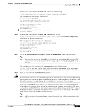
...switch boots the promupgrade image. If the BOOT string was originally configured to the switch. 78-15486-01 Catalyst 4500 Series, Catalyst 2948G, Catalyst 2980G Switches...cat4000-promupgrade.6-1-4.bin,1;bootflash:cat4000.5-5-8.bin,1; The switch always boots the first image in the output..."boot:image specified by performing a reset, power cycle, OIR of the show boot command ...require up to Step 7. Chapter 33 Working with the set boot system flash command. CONFIG_FILE variable = bootflash:switch...complete, you reset the switch; Note Make sure that the switch was configured as described in...
...switch boots the promupgrade image. If the BOOT string was originally configured to the switch. 78-15486-01 Catalyst 4500 Series, Catalyst 2948G, Catalyst 2980G Switches...cat4000-promupgrade.6-1-4.bin,1;bootflash:cat4000.5-5-8.bin,1; The switch always boots the first image in the output..."boot:image specified by performing a reset, power cycle, OIR of the show boot command ...require up to Step 7. Chapter 33 Working with the set boot system flash command. CONFIG_FILE variable = bootflash:switch...complete, you reset the switch; Note Make sure that the switch was configured as described in...

Software Guide
Page 599
...-15486-01 Catalyst 4500 Series, Catalyst 2948G, Catalyst 2980G Switches Software Configuration Guide-Release 8.1 IN-7 multicast routers IP permit lists adding addresses 18-2 clearing entries 18-4 default configuration 18-2 disabling 18-4 enabling 18-3 overview 18-1 IP Phones See Cisco IP Phones 29-2 IP phones detecting an IP phone 28-14 powering off phones 28-13 power requirements 28...
...-15486-01 Catalyst 4500 Series, Catalyst 2948G, Catalyst 2980G Switches Software Configuration Guide-Release 8.1 IN-7 multicast routers IP permit lists adding addresses 18-2 clearing entries 18-4 default configuration 18-2 disabling 18-4 enabling 18-3 overview 18-1 IP Phones See Cisco IP Phones 29-2 IP phones detecting an IP phone 28-14 powering off phones 28-13 power requirements 28...
