
Hardware Installation Guide
Page 6
...12 RPS LED 1-13 Port LEDs and Modes 1-14 Module Slot LEDs 1-19 Rear-Panel Description 1-19 Power Connectors 1-21 Internal Power Supply Connector 1-21 DC Power Connector 1-21 Cisco... RPS Connector 1-22 Console Port 1-23 2 C H A P T E R Installation 2-1 Preparing for Installation 2-1 Warnings 2-1 EMC Regulatory Statements 2-4 U.S.A. 2-4 Taiwan 2-4 Japan 2-5 Korea 2-5 Hungary 2-6 Installation Guidelines 2-6 Verifying Package Contents 2-7 Installing the Switch on a Table or Shelf 2-9 Installing the Switch in a Rack 2-9 Removing Screws from the Switch 2-11 Attaching the Brackets to a Catalyst...
...12 RPS LED 1-13 Port LEDs and Modes 1-14 Module Slot LEDs 1-19 Rear-Panel Description 1-19 Power Connectors 1-21 Internal Power Supply Connector 1-21 DC Power Connector 1-21 Cisco... RPS Connector 1-22 Console Port 1-23 2 C H A P T E R Installation 2-1 Preparing for Installation 2-1 Warnings 2-1 EMC Regulatory Statements 2-4 U.S.A. 2-4 Taiwan 2-4 Japan 2-5 Korea 2-5 Hungary 2-6 Installation Guidelines 2-6 Verifying Package Contents 2-7 Installing the Switch on a Table or Shelf 2-9 Installing the Switch in a Rack 2-9 Removing Screws from the Switch 2-11 Attaching the Brackets to a Catalyst...

Hardware Installation Guide
Page 7
...18 Attaching the Optional Cable Guide 2-19 Installing the Switch on a Wall 2-20 Attaching the Brackets to the Switch 2-21 Mounting the Switch to a Wall 2-22 Powering On the Switch and Running POST 2-24 Connecting to DC Power 2-25 Preparing for Installation 2-25 Grounding the Switch 2-26 Wiring the DC-Input Power Source 2-29... Correcting Module POST Failures 3-2 Diagnosing Problems 3-3 Technical Specifications A-1 Connectors and Cable Specifications B-1 Connector Specifications B-1 10/100 Ports B-1 100BASE-FX Ports B-2 Contents 78-6461-04 Catalyst 2900 Series XL Hardware Installation Guide vii
...18 Attaching the Optional Cable Guide 2-19 Installing the Switch on a Wall 2-20 Attaching the Brackets to the Switch 2-21 Mounting the Switch to a Wall 2-22 Powering On the Switch and Running POST 2-24 Connecting to DC Power 2-25 Preparing for Installation 2-25 Grounding the Switch 2-26 Wiring the DC-Input Power Source 2-29... Correcting Module POST Failures 3-2 Diagnosing Problems 3-3 Technical Specifications A-1 Connectors and Cable Specifications B-1 Connector Specifications B-1 10/100 Ports B-1 100BASE-FX Ports B-2 Contents 78-6461-04 Catalyst 2900 Series XL Hardware Installation Guide vii

Hardware Installation Guide
Page 9
INDEX Class 1 Laser Product Warning C-22 Laser Beam Exposure Warning C-23 No On/Off Switch Warning C-24 Chassis Warning-Rack-Mounting and Servicing C-25 Reinforced Insulation Warning C-29 LAN Connections Only Warning C-30 No Field-Replaceable Units Warning C-31 Installation ... Equipment Warning C-36 Ground Connection Warning C-37 Qualified Personnel Warning C-38 DC Power Disconnection Warning C-39 Exposed Wire Lead Warning C-41 Contents 78-6461-04 Catalyst 2900 Series XL Hardware Installation Guide ix
INDEX Class 1 Laser Product Warning C-22 Laser Beam Exposure Warning C-23 No On/Off Switch Warning C-24 Chassis Warning-Rack-Mounting and Servicing C-25 Reinforced Insulation Warning C-29 LAN Connections Only Warning C-30 No Field-Replaceable Units Warning C-31 Installation ... Equipment Warning C-36 Ground Connection Warning C-37 Qualified Personnel Warning C-38 DC Power Disconnection Warning C-39 Exposed Wire Lead Warning C-41 Contents 78-6461-04 Catalyst 2900 Series XL Hardware Installation Guide ix

Hardware Installation Guide
Page 11
... area networking. Chapter 2, "Installation," provides the procedures for installing and configuring a Catalyst 2900 series XL switch. It describes the physical and performance characteristics of Catalyst 2900 series XL switches. We assume that might arise when you are installing the switch. 78-6461-04 Catalyst 2900 Series XL Hardware Installation Guide xi Organization This guide is for...
... area networking. Chapter 2, "Installation," provides the procedures for installing and configuring a Catalyst 2900 series XL switch. It describes the physical and performance characteristics of Catalyst 2900 series XL switches. We assume that might arise when you are installing the switch. 78-6461-04 Catalyst 2900 Series XL Hardware Installation Guide xi Organization This guide is for...

Hardware Installation Guide
Page 12
Examples use these conventions: • Commands and keywords are in boldface. • Arguments for the switches and the regulatory agency approvals. Catalyst 2900 Series XL Hardware Installation Guide xii 78-6461-04 Conventions Preface Appendix A, "Technical Specifications," ...adapters that could result in equipment damage or loss of the warnings in this guide. Notes contain helpful suggestions or references to the switch. Caution Means reader be used to connect to materials not contained in this manual. Appendix C, "Translated Safety Warnings," provides translations in...
Examples use these conventions: • Commands and keywords are in boldface. • Arguments for the switches and the regulatory agency approvals. Catalyst 2900 Series XL Hardware Installation Guide xii 78-6461-04 Conventions Preface Appendix A, "Technical Specifications," ...adapters that could result in equipment damage or loss of the warnings in this guide. Notes contain helpful suggestions or references to the switch. Caution Means reader be used to connect to materials not contained in this manual. Appendix C, "Translated Safety Warnings," provides translations in...

Hardware Installation Guide
Page 15
... only in the "Obtaining Documentation" section on page xvi. • Release Notes for the Catalyst 2900 Series XL and Catalyst 3500 Series XL Switches (not orderable but is available on Cisco.com for the latest information. 78-6461-04 Catalyst 2900 Series XL Hardware Installation Guide xv Antes de manipular cualquier equipo, considerar los riesgos...
... only in the "Obtaining Documentation" section on page xvi. • Release Notes for the Catalyst 2900 Series XL and Catalyst 3500 Series XL Switches (not orderable but is available on Cisco.com for the latest information. 78-6461-04 Catalyst 2900 Series XL Hardware Installation Guide xv Antes de manipular cualquier equipo, considerar los riesgos...

Hardware Installation Guide
Page 16
... online help (available only from the switch CMS software) • Catalyst 2900 Series XL Hardware Installation Guide (order number DOC-786461=) • Catalyst 3500 Series XL Hardware Installation Guide (order number DOC-786456=) • Catalyst 2900 Series XL Modules Installation Guide (order...1000BASE-T Gigabit Interface Converter Installation Note (not orderable but is available on Cisco.com) • Catalyst GigaStack Gigabit Interface Converter Hardware Installation Guide (order number DOC-786460=) • Cisco LRE CPE Hardware Installation Guide (order number DOC-7811469=) • ...
... online help (available only from the switch CMS software) • Catalyst 2900 Series XL Hardware Installation Guide (order number DOC-786461=) • Catalyst 3500 Series XL Hardware Installation Guide (order number DOC-786456=) • Catalyst 2900 Series XL Modules Installation Guide (order...1000BASE-T Gigabit Interface Converter Installation Note (not orderable but is available on Cisco.com) • Catalyst GigaStack Gigabit Interface Converter Hardware Installation Guide (order number DOC-786460=) • Cisco LRE CPE Hardware Installation Guide (order number DOC-7811469=) • ...

Hardware Installation Guide
Page 21
The Catalyst 2900 XL switches have these topics that allows an Ethernet network to reach distances up to 4921 feet (1500 meters). The switches can connect workstations, Cisco IP Phones, and other network devices such as servers, routers, and other network devices. CH A P T E R 1 Product Overview This... and rear panels • Descriptions of the LEDs Features The switches are stackable 10/100 Ethernet switches to the destination port 78-6461-04 Catalyst 2900 Series XL Hardware Installation Guide 1-1 The 2900 XL LRE switches employ Long-Reach Ethernet (LRE), a very-high-data-rate ...
The Catalyst 2900 XL switches have these topics that allows an Ethernet network to reach distances up to 4921 feet (1500 meters). The switches can connect workstations, Cisco IP Phones, and other network devices such as servers, routers, and other network devices. CH A P T E R 1 Product Overview This... and rear panels • Descriptions of the LEDs Features The switches are stackable 10/100 Ethernet switches to the destination port 78-6461-04 Catalyst 2900 Series XL Hardware Installation Guide 1-1 The 2900 XL LRE switches employ Long-Reach Ethernet (LRE), a very-high-data-rate ...

Hardware Installation Guide
Page 22
... • On the Catalyst 2912 LRE XL and 2924 LRE XL switches, up to 24 LRE ports through one RJ-21 connector and hot swapping capability with the Cisco LRE customer premises equipment (CPE) devices • Supports up to 2048 MAC addresses on the Catalyst 2924 XL, 2924C XL..., and 2912 XL switches • Supports up to 8192 MAC addresses on the Catalyst 2924M XL, Catalyst 2924M XL DC and Catalyst 2912MF XL switches Figure 1-1 shows the switch models. Catalyst ...
... • On the Catalyst 2912 LRE XL and 2924 LRE XL switches, up to 24 LRE ports through one RJ-21 connector and hot swapping capability with the Cisco LRE customer premises equipment (CPE) devices • Supports up to 2048 MAC addresses on the Catalyst 2924 XL, 2924C XL..., and 2912 XL switches • Supports up to 8192 MAC addresses on the Catalyst 2924M XL, Catalyst 2924M XL DC and Catalyst 2912MF XL switches Figure 1-1 shows the switch models. Catalyst ...

Hardware Installation Guide
Page 23
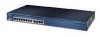
Chapter 1 Product Overview Figure 1-1 Catalyst 2900 Series XL Switches Version Number Description WS-C2912-LRE-XL 4 fixed autosensing 10/100 ports INPUT OUTPUT PWR PWR RESET TEMP FAN 9X 10X 11X 12X 12 LRE ports Cisco RPS 300 WS-C2924-LRE-XL 4 fixed autosensing 10/100 ports 24 LRE ports INPUT OUTPUT PWR PWR RESET... TEMP FAN 9X 10X 11X 12X Cisco RPS 300 WS-C2912-XL 12 fixed autosensing 10/100 ports MODE 1X 2X 3X 4X 5X 6X 7X 8X 9X 10X 10BaseT/100BASE-TX 11X 12X Catalyst 2900 SERIES XL WS-C2924C-XL 22 fixed autosensing 10/100 ports...
Chapter 1 Product Overview Figure 1-1 Catalyst 2900 Series XL Switches Version Number Description WS-C2912-LRE-XL 4 fixed autosensing 10/100 ports INPUT OUTPUT PWR PWR RESET TEMP FAN 9X 10X 11X 12X 12 LRE ports Cisco RPS 300 WS-C2924-LRE-XL 4 fixed autosensing 10/100 ports 24 LRE ports INPUT OUTPUT PWR PWR RESET... TEMP FAN 9X 10X 11X 12X Cisco RPS 300 WS-C2912-XL 12 fixed autosensing 10/100 ports MODE 1X 2X 3X 4X 5X 6X 7X 8X 9X 10X 10BaseT/100BASE-TX 11X 12X Catalyst 2900 SERIES XL WS-C2924C-XL 22 fixed autosensing 10/100 ports...

Hardware Installation Guide
Page 24
... management station. • Simple network management protocol (SNMP)-SNMP provides a means to modify switch- You can fully configure and monitor the switch and switch cluster members from anywhere in your management station directly to the Catalyst 2900 Series XL and Catalyst 3500 Series XL Software Configuration Guide. This section describes these interfaces: • Cluster Management...
... management station. • Simple network management protocol (SNMP)-SNMP provides a means to modify switch- You can fully configure and monitor the switch and switch cluster members from anywhere in your management station directly to the Catalyst 2900 Series XL and Catalyst 3500 Series XL Software Configuration Guide. This section describes these interfaces: • Cluster Management...

Hardware Installation Guide
Page 26
...Cisco IP Phones, servers, hubs, routers, and other switches through , twisted-pair cable. The 10/100 switch ports can use a crossover cable. If the connected device also supports autonegotiation, the switch port negotiates the best connection (that is required for more info on the Catalyst 2900 XL switches... Unlike the 3524-PWR XL switch, the Catalyst 2900 XL switches do not provide inline power. When connecting the switch to switches or hubs, use Category 3 and 4 cables. The 10/100 ports on the Catalyst 3524-PWR XL switch, refer to the Catalyst 3500 Series XL Hardware Installation...
...Cisco IP Phones, servers, hubs, routers, and other switches through , twisted-pair cable. The 10/100 switch ports can use a crossover cable. If the connected device also supports autonegotiation, the switch port negotiates the best connection (that is required for more info on the Catalyst 2900 XL switches... Unlike the 3524-PWR XL switch, the Catalyst 2900 XL switches do not provide inline power. When connecting the switch to switches or hubs, use Category 3 and 4 cables. The 10/100 ports on the Catalyst 3524-PWR XL switch, refer to the Catalyst 3500 Series XL Hardware Installation...

Hardware Installation Guide
Page 27
... connector to connect up to 4921 feet (1500 meters). You can connect Cisco 575 LRE CPE and Cisco 585 LRE CPE devices to LRE ports on the same Catalyst 2900 LRE XL switch, and you can be over distances of up to 24 Cisco LRE customer premises equipment (CPE) devices though structured or unstructured wiring... device can be used. The default mode for half-duplex operation, the connection can be connected to the patch panel through a private branch exchange (PBX) switch, a Cisco LRE 48 POTS Splitter can hot swap the CPE devices without powering down the...
... connector to connect up to 4921 feet (1500 meters). You can connect Cisco 575 LRE CPE and Cisco 585 LRE CPE devices to LRE ports on the same Catalyst 2900 LRE XL switch, and you can be over distances of up to 24 Cisco LRE customer premises equipment (CPE) devices though structured or unstructured wiring... device can be used. The default mode for half-duplex operation, the connection can be connected to the patch panel through a private branch exchange (PBX) switch, a Cisco LRE 48 POTS Splitter can hot swap the CPE devices without powering down the...

Hardware Installation Guide
Page 28
For more information about homologated POTS splitters, contact your Cisco sales representative. Due to the proprietary nature of digital PBX switches, some digital PBX switch services use the 0 to the Installation Notes for the Catalyst 2900 XL hot-swappable modules. Module Slots The module slots (see Figure 1-2) are ... WS-X2914-XL WS-X2914-XL-V WS-X2922-XL WS-X2922-XL-V WS-X2924-XL-V Catalyst 2900 Series XL Hardware Installation Guide 1-8 78-6461-04 For more information about the Cisco LRE 48 POTS Splitter (PS-1M-LRE-48), refer to 700 kHz frequency range. Note ...
For more information about homologated POTS splitters, contact your Cisco sales representative. Due to the proprietary nature of digital PBX switches, some digital PBX switch services use the 0 to the Installation Notes for the Catalyst 2900 XL hot-swappable modules. Module Slots The module slots (see Figure 1-2) are ... WS-X2914-XL WS-X2914-XL-V WS-X2922-XL WS-X2922-XL-V WS-X2924-XL-V Catalyst 2900 Series XL Hardware Installation Guide 1-8 78-6461-04 For more information about the Cisco LRE 48 POTS Splitter (PS-1M-LRE-48), refer to 700 kHz frequency range. Note ...

Hardware Installation Guide
Page 29
... LEDs 78-6461-04 You can start the module by each port LED. A power-on expansion modules for the Catalyst 2900 Series XL and Catalyst 3500 Series XL Switches. Changing a port mode changes the information provided by restarting that you install one of the LEDs and the Mode ...show the location of these modules in module slots and tighten the thumb screws. If you use the switch LEDs to the Catalyst 2900 Series XL Modules Installation Guide and the Catalyst 2900 Series XL ATM Modules Installation and Configuration Guide for detailed information on self-test (POST) verifies ...
... LEDs 78-6461-04 You can start the module by each port LED. A power-on expansion modules for the Catalyst 2900 Series XL and Catalyst 3500 Series XL Switches. Changing a port mode changes the information provided by restarting that you install one of the LEDs and the Mode ...show the location of these modules in module slots and tighten the thumb screws. If you use the switch LEDs to the Catalyst 2900 Series XL Modules Installation Guide and the Catalyst 2900 Series XL ATM Modules Installation and Configuration Guide for detailed information on self-test (POST) verifies ...

Hardware Installation Guide
Page 30
... the utilization meter (UTL) are visible on the Cluster Management Suite (CMS) window and, if the switch is a cluster member, on the CMS Cluster Manager window. The Catalyst 2900 Series XL and Catalyst 3500 Series XL Software Configuration Guide describes how to use CMS to manage standalone or individual... switches and how to use cluster management software to manage switch clusters]. Figure 1-5 Catalyst 2912 XL, 2924 XL, and 2924C XL LEDs 10/100 port LEDs System LED Port mode LEDs MODE 1X 2X...
... the utilization meter (UTL) are visible on the Cluster Management Suite (CMS) window and, if the switch is a cluster member, on the CMS Cluster Manager window. The Catalyst 2900 Series XL and Catalyst 3500 Series XL Software Configuration Guide describes how to use CMS to manage standalone or individual... switches and how to use cluster management software to manage switch clusters]. Figure 1-5 Catalyst 2912 XL, 2924 XL, and 2924C XL LEDs 10/100 port LEDs System LED Port mode LEDs MODE 1X 2X...

Hardware Installation Guide
Page 32
... lists the LED colors and their meanings. For information on the System LED colors during POST, see the "Powering On the Switch and Running POST" section on page 2-24. 1-12 Catalyst 2900 Series XL Hardware Installation Guide 78-6461-04 System is not functioning properly. Front-Panel Description Figure... 1-7 Catalyst 2912 LRE XL and 2924 LRE XL LEDs 10/100 port LEDs Chapter 1 Product Overview SYSTEM RPS MODE LRE ...
... lists the LED colors and their meanings. For information on the System LED colors during POST, see the "Powering On the Switch and Running POST" section on page 2-24. 1-12 Catalyst 2900 Series XL Hardware Installation Guide 78-6461-04 System is not functioning properly. Front-Panel Description Figure... 1-7 Catalyst 2912 LRE XL and 2924 LRE XL LEDs 10/100 port LEDs Chapter 1 Product Overview SYSTEM RPS MODE LRE ...

Hardware Installation Guide
Page 33
...another device (redundancy has been allocated to the appropriate switch documentation for redundant power system (RPS) descriptions specific for the switch. Pressing the Mode button on page 1-22. All other Catalyst 2900 XL and Catalyst 3500 XL switches use the Cisco RPS 300 (model PWR300-AC-RPS-N1). The ...Note This is not installed. Chapter 1 Product Overview Front-Panel Description RPS LED The Catalyst 2912 LRE XL and Catalyst 2924 LRE XL switches use the Cisco RPS 600 (model PWR600-AC-RPS). The switch goes through its normal boot sequence when it in Ready mode, and the LED ...
...another device (redundancy has been allocated to the appropriate switch documentation for redundant power system (RPS) descriptions specific for the switch. Pressing the Mode button on page 1-22. All other Catalyst 2900 XL and Catalyst 3500 XL switches use the Cisco RPS 300 (model PWR300-AC-RPS-N1). The ...Note This is not installed. Chapter 1 Product Overview Front-Panel Description RPS LED The Catalyst 2912 LRE XL and Catalyst 2924 LRE XL switches use the Cisco RPS 600 (model PWR600-AC-RPS). The switch goes through its normal boot sequence when it in Ready mode, and the LED ...

Hardware Installation Guide
Page 34
... modes: • 10/100 ports: auto • 100BaseFX ports: auto • Gigabit ports: auto The port operating speed: 10 or 100 Mbps. 1-14 Catalyst 2900 Series XL Hardware Installation Guide 78-6461-04 The port modes (Table 1-4 and Table 1-5) determine the type of the port LED colors also changes...-FX, and LRE ports and module slots have failed. To select or change port modes, the meaning of information displayed. Contact Cisco Systems. The internal power supply in a switch has failed, and the RPS is highlighted. If it does not, the RPS fan could have a port LED. This is the...
... modes: • 10/100 ports: auto • 100BaseFX ports: auto • Gigabit ports: auto The port operating speed: 10 or 100 Mbps. 1-14 Catalyst 2900 Series XL Hardware Installation Guide 78-6461-04 The port modes (Table 1-4 and Table 1-5) determine the type of the port LED colors also changes...-FX, and LRE ports and module slots have failed. To select or change port modes, the meaning of information displayed. Contact Cisco Systems. The internal power supply in a switch has failed, and the RPS is highlighted. If it does not, the RPS fan could have a port LED. This is the...

Hardware Installation Guide
Page 35
... duplex mode: full duplex or half duplex. Chapter 1 Product Overview Front-Panel Description Table 1-5 Port Mode LEDs on Catalyst 2912 LRE XL and 2924 LRE XL Switches Mode LED LRE STAT DUPLX SPEED Port Mode LRE link status Port status Port duplex mode Port speed Description Long-Reach ...status of the 10/100 or 100BASE-FX switch ports or the Ethernet link status on these switches only. Ethernet link status of the LRE ports on all Catalyst 2900 XL and Catalyst 3500 XL switches except the Catalyst 2912 LRE XL and Catalyst 2924 LRE XL switches. The default setting is half duplex. Default...
... duplex mode: full duplex or half duplex. Chapter 1 Product Overview Front-Panel Description Table 1-5 Port Mode LEDs on Catalyst 2912 LRE XL and 2924 LRE XL Switches Mode LED LRE STAT DUPLX SPEED Port Mode LRE link status Port status Port duplex mode Port speed Description Long-Reach ...status of the 10/100 or 100BASE-FX switch ports or the Ethernet link status on these switches only. Ethernet link status of the LRE ports on all Catalyst 2900 XL and Catalyst 3500 XL switches except the Catalyst 2912 LRE XL and Catalyst 2924 LRE XL switches. The default setting is half duplex. Default...


