
Hardware Installation Guide
Page 6
... 1-21 DC Power Connector 1-21 Cisco RPS Connector 1-22 Console Port 1-23 2 C H A P T E R Installation 2-1 Preparing for Installation 2-1 Warnings 2-1 EMC Regulatory Statements 2-4 U.S.A. 2-4 Taiwan 2-4 Japan 2-5 Korea 2-5 Hungary 2-6 Installation Guidelines 2-6 Verifying Package Contents 2-7 Installing the Switch on a Table or Shelf 2-9 Installing the Switch in a Rack 2-9 Removing Screws from the Switch 2-11 Attaching the Brackets to a Catalyst 2912 XL, 2924C XL...
... 1-21 DC Power Connector 1-21 Cisco RPS Connector 1-22 Console Port 1-23 2 C H A P T E R Installation 2-1 Preparing for Installation 2-1 Warnings 2-1 EMC Regulatory Statements 2-4 U.S.A. 2-4 Taiwan 2-4 Japan 2-5 Korea 2-5 Hungary 2-6 Installation Guidelines 2-6 Verifying Package Contents 2-7 Installing the Switch on a Table or Shelf 2-9 Installing the Switch in a Rack 2-9 Removing Screws from the Switch 2-11 Attaching the Brackets to a Catalyst 2912 XL, 2924C XL...

Hardware Installation Guide
Page 7
...the Switch 2-26 Wiring the DC-Input Power Source 2-29 Connecting to a 10/100 Port 2-35 Connecting to a 100BASE-FX Port 2-37 Connecting to an LRE Port 2-38 Connecting to a Module Port 2-42 Connecting to the Console Port 2-...42 Where to Go Next 2-43 Troubleshooting 3-1 Understanding POST Results 3-1 Correcting Module POST Failures 3-2 Diagnosing Problems 3-3 Technical Specifications A-1 Connectors and Cable Specifications B-1 Connector Specifications B-1 10/100 Ports B-1 100BASE-FX Ports B-2 Contents 78-6461-04 Catalyst...
...the Switch 2-26 Wiring the DC-Input Power Source 2-29 Connecting to a 10/100 Port 2-35 Connecting to a 100BASE-FX Port 2-37 Connecting to an LRE Port 2-38 Connecting to a Module Port 2-42 Connecting to the Console Port 2-...42 Where to Go Next 2-43 Troubleshooting 3-1 Understanding POST Results 3-1 Correcting Module POST Failures 3-2 Diagnosing Problems 3-3 Technical Specifications A-1 Connectors and Cable Specifications B-1 Connector Specifications B-1 10/100 Ports B-1 100BASE-FX Ports B-2 Contents 78-6461-04 Catalyst...

Hardware Installation Guide
Page 11
...or computer technician responsible for installing a switch in a rack, on a desk, or on a wall. It describes the physical and performance characteristics of Catalyst 2900 series XL switches. Chapter 3, "Troubleshooting," describes how to install a switch, and provides troubleshooting information and specifications...2, "Installation," provides the procedures for installing and configuring a Catalyst 2900 series XL switch. We assume that might arise when you are installing the switch. 78-6461-04 Catalyst 2900 Series XL Hardware Installation Guide xi Preface Audience This guide ...
...or computer technician responsible for installing a switch in a rack, on a desk, or on a wall. It describes the physical and performance characteristics of Catalyst 2900 series XL switches. Chapter 3, "Troubleshooting," describes how to install a switch, and provides troubleshooting information and specifications...2, "Installation," provides the procedures for installing and configuring a Catalyst 2900 series XL switch. We assume that might arise when you are installing the switch. 78-6461-04 Catalyst 2900 Series XL Hardware Installation Guide xi Preface Audience This guide ...

Hardware Installation Guide
Page 21
... destination port, stores the packet in shared memory, and then forwards the packet to which you can be deployed as servers, routers, and other network devices. The Catalyst 2900 XL switches have these topics that allows an Ethernet network to reach distances up to 4921 feet (1500 meters). The switches can connect workstations, Cisco IP...
... destination port, stores the packet in shared memory, and then forwards the packet to which you can be deployed as servers, routers, and other network devices. The Catalyst 2900 XL switches have these topics that allows an Ethernet network to reach distances up to 4921 feet (1500 meters). The switches can connect workstations, Cisco IP...

Hardware Installation Guide
Page 22
... asynchronous transfer mode (ATM) modules • On the Catalyst 2924M XL DC switch, a direct current (DC) power converter • On the Catalyst 2912 LRE XL and 2924 LRE XL switches, up to 24 LRE ports through one RJ-21 connector and hot swapping capability with the Cisco LRE customer premises equipment (CPE) devices • Supports up...
... asynchronous transfer mode (ATM) modules • On the Catalyst 2924M XL DC switch, a direct current (DC) power converter • On the Catalyst 2912 LRE XL and 2924 LRE XL switches, up to 24 LRE ports through one RJ-21 connector and hot swapping capability with the Cisco LRE customer premises equipment (CPE) devices • Supports up...

Hardware Installation Guide
Page 23
... 1 Product Overview Figure 1-1 Catalyst 2900 Series XL Switches Version Number Description WS-C2912-LRE-XL 4 fixed autosensing 10/100 ports INPUT OUTPUT PWR PWR RESET TEMP FAN 9X 10X 11X 12X 12 LRE ports Cisco RPS 300 WS-C2924-LRE-XL 4 fixed autosensing 10/100 ports 24 LRE ports INPUT OUTPUT PWR PWR RESET TEMP... FAN 9X 10X 11X 12X Cisco RPS 300 WS-C2912-XL 12 fixed autosensing 10/100 ports MODE 1X 2X 3X 4X 5X 6X 7X 8X 9X 10X 10BaseT/100BASE-TX 11X 12X Catalyst 2900 SERIES XL WS-C2924C...
... 1 Product Overview Figure 1-1 Catalyst 2900 Series XL Switches Version Number Description WS-C2912-LRE-XL 4 fixed autosensing 10/100 ports INPUT OUTPUT PWR PWR RESET TEMP FAN 9X 10X 11X 12X 12 LRE ports Cisco RPS 300 WS-C2924-LRE-XL 4 fixed autosensing 10/100 ports 24 LRE ports INPUT OUTPUT PWR PWR RESET TEMP... FAN 9X 10X 11X 12X Cisco RPS 300 WS-C2912-XL 12 fixed autosensing 10/100 ports MODE 1X 2X 3X 4X 5X 6X 7X 8X 9X 10X 10BaseT/100BASE-TX 11X 12X Catalyst 2900 SERIES XL WS-C2924C...

Hardware Installation Guide
Page 24
... using Telnet from the CLI. You can have a set of LEDs and a Mode button. All switches have up to twenty-four 10/100 ports (See Figure 1-2), up to twelve 100BASE-FX ports (See Figure 1-3), two module slots (see Figure 1-3), and up to the Catalyst 2900 Series XL and Catalyst 3500 Series XL Software Configuration Guide.
... using Telnet from the CLI. You can have a set of LEDs and a Mode button. All switches have up to twenty-four 10/100 ports (See Figure 1-2), up to twelve 100BASE-FX ports (See Figure 1-3), two module slots (see Figure 1-3), and up to the Catalyst 2900 Series XL and Catalyst 3500 Series XL Software Configuration Guide.

Hardware Installation Guide
Page 26
... devices, such as high-speed workstations, Cisco IP Phones, servers, hubs, routers, and other switches through , twisted-pair cable. Unlike the 3524-PWR XL switch, the Catalyst 2900 XL switches do not provide inline power. When connecting the switch to switches or hubs, use Category 3 and 4 cables. Pinouts for autonegotiation, the port senses the speed and duplex settings...
... devices, such as high-speed workstations, Cisco IP Phones, servers, hubs, routers, and other switches through , twisted-pair cable. Unlike the 3524-PWR XL switch, the Catalyst 2900 XL switches do not provide inline power. When connecting the switch to switches or hubs, use Category 3 and 4 cables. Pinouts for autonegotiation, the port senses the speed and duplex settings...

Hardware Installation Guide
Page 27
... system telephone network 78-6461-04 Catalyst 2900 Series XL Hardware Installation Guide 1-7 The connection distances between the LRE switch port and each LRE port is speed autonegotiation and half-duplex operation. For information about the Cisco LRE CPE devices, refer to the switch and private branch exchange (PBX) switch or Public-Switched Telephone Network (PSTN). Long-Reach...
... system telephone network 78-6461-04 Catalyst 2900 Series XL Hardware Installation Guide 1-7 The connection distances between the LRE switch port and each LRE port is speed autonegotiation and half-duplex operation. For information about the Cisco LRE CPE devices, refer to the switch and private branch exchange (PBX) switch or Public-Switched Telephone Network (PSTN). Long-Reach...

Hardware Installation Guide
Page 28
...-LRE-48), refer to digital PBX switches that the module slots support. Note Cisco Long-Reach Ethernet (LRE) products are for the Cisco LRE 48 POTS Splitter. Digital telephones connected to the Installation Notes for the Catalyst 2900 XL hot-swappable modules. Table ...designed to the patch panel. For more information about homologated POTS splitters, contact your Cisco sales representative. Each module port is internally switched to other switch ports and is not needed, and the switch can connect directly to share lines with LRE signals. Front-Panel Description Chapter 1 ...
...-LRE-48), refer to digital PBX switches that the module slots support. Note Cisco Long-Reach Ethernet (LRE) products are for the Cisco LRE 48 POTS Splitter. Digital telephones connected to the Installation Notes for the Catalyst 2900 XL hot-swappable modules. Table ...designed to the patch panel. For more information about homologated POTS splitters, contact your Cisco sales representative. Each module port is internally switched to other switch ports and is not needed, and the switch can connect directly to share lines with LRE signals. Front-Panel Description Chapter 1 ...

Hardware Installation Guide
Page 29
... LEDs 78-6461-04 You can start the module by each port LED. You can use to select a port mode. A power-on expansion modules for the Catalyst 2900 Series XL and Catalyst 3500 Series XL Switches. For a complete list and the minimum software release required, .... After the restart, the switch address capacity is working properly before it starts forwarding packets. Changing a port mode changes the information provided by restarting that the module is reduced to the Release Notes for Catalyst 2900 series XL switches. Catalyst 2900 Series XL Hardware Installation Guide...
... LEDs 78-6461-04 You can start the module by each port LED. You can use to select a port mode. A power-on expansion modules for the Catalyst 2900 Series XL and Catalyst 3500 Series XL Switches. For a complete list and the minimum software release required, .... After the restart, the switch address capacity is working properly before it starts forwarding packets. Changing a port mode changes the information provided by restarting that the module is reduced to the Release Notes for Catalyst 2900 series XL switches. Catalyst 2900 Series XL Hardware Installation Guide...

Hardware Installation Guide
Page 30
... Series XL and Catalyst 3500 Series XL Software Configuration Guide describes how to use CMS to manage standalone or individual switches and how to use cluster management software to manage switch clusters]. Front-Panel Description Chapter 1 Product Overview All of the LEDs described in this section except the utilization ...visible on the Cluster Management Suite (CMS) window and, if the switch is a cluster member, on the CMS Cluster Manager window. Figure 1-5 Catalyst 2912 XL, 2924 XL, and 2924C XL LEDs 10/100 port LEDs System LED Port mode LEDs MODE 1X 2X 3X 4X 5X 6X 7X Mode RPS button...
... Series XL and Catalyst 3500 Series XL Software Configuration Guide describes how to use CMS to manage standalone or individual switches and how to use cluster management software to manage switch clusters]. Front-Panel Description Chapter 1 Product Overview All of the LEDs described in this section except the utilization ...visible on the Cluster Management Suite (CMS) window and, if the switch is a cluster member, on the CMS Cluster Manager window. Figure 1-5 Catalyst 2912 XL, 2924 XL, and 2924C XL LEDs 10/100 port LEDs System LED Port mode LEDs MODE 1X 2X 3X 4X 5X 6X 7X Mode RPS button...

Hardware Installation Guide
Page 32
System is receiving power but is receiving power and functioning properly. Front-Panel Description Figure 1-7 Catalyst 2912 LRE XL and 2924 LRE XL LEDs 10/100 port LEDs Chapter 1 Product Overview SYSTEM RPS MODE LRE STAT DUPLX SPEED Mode button 1X 2X 3X 4X System LED RPS LED LRE... Speed LED LRE port LEDs 1-12 LRE port LEDs 13-24 48002 System LED The system LED shows whether the system is not functioning properly. For information on the System LED colors during POST, see the "Powering On the Switch and Running POST" section on page 2-24. 1-12 Catalyst 2900 Series XL ...
System is receiving power but is receiving power and functioning properly. Front-Panel Description Figure 1-7 Catalyst 2912 LRE XL and 2924 LRE XL LEDs 10/100 port LEDs Chapter 1 Product Overview SYSTEM RPS MODE LRE STAT DUPLX SPEED Mode button 1X 2X 3X 4X System LED RPS LED LRE... Speed LED LRE port LEDs 1-12 LRE port LEDs 13-24 48002 System LED The system LED shows whether the system is not functioning properly. For information on the System LED colors during POST, see the "Powering On the Switch and Running POST" section on page 2-24. 1-12 Catalyst 2900 Series XL ...

Hardware Installation Guide
Page 34
...1-6 and Table 1-7 list the port LED colors. Press the Standby/Active button on the Catalyst 2912 XL, 2924C XL, 2924 XL, 2924MF XL, 2924M XL, and 2924M XL DC Switches Mode LED STAT UTL FDUP 100 Port Mode Port status Switch utilization Port duplex mode Port speed Description The port status. When you change a... is providing power to the switch (redundancy has been allocated to this device). If it does not, the RPS fan could have a port LED. Contact Cisco Systems. The internal power supply in a switch has failed, and the RPS is the default mode. Table 1-4 Port Mode LEDs on the RPS,...
...1-6 and Table 1-7 list the port LED colors. Press the Standby/Active button on the Catalyst 2912 XL, 2924C XL, 2924 XL, 2924MF XL, 2924M XL, and 2924M XL DC Switches Mode LED STAT UTL FDUP 100 Port Mode Port status Switch utilization Port duplex mode Port speed Description The port status. When you change a... is providing power to the switch (redundancy has been allocated to this device). If it does not, the RPS fan could have a port LED. Contact Cisco Systems. The internal power supply in a switch has failed, and the RPS is the default mode. Table 1-4 Port Mode LEDs on the RPS,...

Hardware Installation Guide
Page 35
...status of the 10/100 or 100BASE-FX switch ports or the Ethernet link status on the remote CPE. Ethernet link status of the LRE ports on all Catalyst 2900 XL and Catalyst 3500 XL switches except the Catalyst 2912 LRE XL and Catalyst 2924 LRE XL switches. The default setting is auto. 78-...6461-04 Catalyst 2900 Series XL Hardware Installation Guide 1-15 The port operating speed: 10 or 100 Mbps....
...status of the 10/100 or 100BASE-FX switch ports or the Ethernet link status on the remote CPE. Ethernet link status of the LRE ports on all Catalyst 2900 XL and Catalyst 3500 XL switches except the Catalyst 2912 LRE XL and Catalyst 2924 LRE XL switches. The default setting is auto. 78-...6461-04 Catalyst 2900 Series XL Hardware Installation Guide 1-15 The port operating speed: 10 or 100 Mbps....

Hardware Installation Guide
Page 55
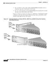
..., you must first remove screws in the switch chassis so that you use depend on page 2-19 Removing Screws from the Switch Catalyst 2900 SERIES XL Fixed-port Catalyst 2900 series XL Catalyst 2900 SERIES XL 22X 23X 24X Modular Catalyst 2900 series XL 47292 Attaching the Brackets to a Catalyst 2912 XL, 2924C XL, 2924 XL,...-, 23-, or 24-inch rack. Use two of the supplied screws to attach each bracket, according to remove the chassis screws in a fixed-port and a modular port switch. Figure 2-3 shows how to rack size: 78-6461-04 Catalyst 2900 Series XL Hardware Installation Guide 2-11
..., you must first remove screws in the switch chassis so that you use depend on page 2-19 Removing Screws from the Switch Catalyst 2900 SERIES XL Fixed-port Catalyst 2900 series XL Catalyst 2900 SERIES XL 22X 23X 24X Modular Catalyst 2900 series XL 47292 Attaching the Brackets to a Catalyst 2912 XL, 2924C XL, 2924 XL,...-, 23-, or 24-inch rack. Use two of the supplied screws to attach each bracket, according to remove the chassis screws in a fixed-port and a modular port switch. Figure 2-3 shows how to rack size: 78-6461-04 Catalyst 2900 Series XL Hardware Installation Guide 2-11
Hardware Installation Guide
Page 56
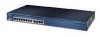
...show how to attach a bracket to the opposite side of the switch. Follow the same steps to attach the second bracket to one side of the switch. Figure 2-4 Attaching Brackets on Catalyst 2912 XL, 2924C XL, and 2924 XL Fixed-Port Switches (Front-Panel Forward) Phillips flat-head screws Phillips truss-head ...screws 19" configuration MODE 1X 2X 3X 4X 5X 6X 7X 47738 23" and 24" configuration MODE 1X 2X 3X 4X 5X 6X 7X 2-12 Catalyst 2900 Series XL Hardware Installation Guide 78...
...show how to attach a bracket to the opposite side of the switch. Follow the same steps to attach the second bracket to one side of the switch. Figure 2-4 Attaching Brackets on Catalyst 2912 XL, 2924C XL, and 2924 XL Fixed-Port Switches (Front-Panel Forward) Phillips flat-head screws Phillips truss-head ...screws 19" configuration MODE 1X 2X 3X 4X 5X 6X 7X 47738 23" and 24" configuration MODE 1X 2X 3X 4X 5X 6X 7X 2-12 Catalyst 2900 Series XL Hardware Installation Guide 78...

Hardware Installation Guide
Page 58
Installing the Switch in a Rack Chapter 2 Installation Figure 2-6 Attaching Brackets on Catalyst 2912 XL, 2924C XL, and 2924 XL Fixed-Port Switches (Rear-Panel Forward) 19" configuration Phillips flat-head screws 23" and 24" configuration Phillips truss-head screws 47298 2-14 Catalyst 2900 Series XL Hardware Installation Guide 78-6461-04
Installing the Switch in a Rack Chapter 2 Installation Figure 2-6 Attaching Brackets on Catalyst 2912 XL, 2924C XL, and 2924 XL Fixed-Port Switches (Rear-Panel Forward) 19" configuration Phillips flat-head screws 23" and 24" configuration Phillips truss-head screws 47298 2-14 Catalyst 2900 Series XL Hardware Installation Guide 78-6461-04
Hardware Installation Guide
Page 65
Chapter 2 Installation Installing the Switch on a Wall Note To mount a Catalyst 2912 LRE XL or 2924 LRE XL switch on a wall, you are attaching the brackets for Fixed-Port Switches 78-6461-04 47303 Phillips truss-head screws Catalyst 2900 Series XL Hardware Installation Guide 2-21 Figure 2-13 Attaching Brackets for...use depend on a wall. Use two of the bracket to these brackets, contact your Cisco sales representative. Follow the same steps to attach the second bracket to one side of the switch. Figure 2-13 and Figure 2-13 show how to attach the brackets to the opposite ...
Chapter 2 Installation Installing the Switch on a Wall Note To mount a Catalyst 2912 LRE XL or 2924 LRE XL switch on a wall, you are attaching the brackets for Fixed-Port Switches 78-6461-04 47303 Phillips truss-head screws Catalyst 2900 Series XL Hardware Installation Guide 2-21 Figure 2-13 Attaching Brackets for...use depend on a wall. Use two of the bracket to these brackets, contact your Cisco sales representative. Follow the same steps to attach the second bracket to one side of the switch. Figure 2-13 and Figure 2-13 show how to attach the brackets to the opposite ...

Hardware Installation Guide
Page 67
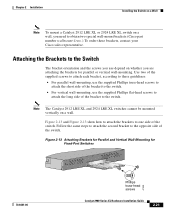
Chapter 2 Installation Installing the Switch on a Wall Figure 2-15 Mounting a Fixed-Port Switch to a Wall Vertical wall stud SERIES 24x 23x User-supplied screws 22x 21x 20x 19x 18x 17x 16x 15x 14x 13x 10BaseT/100BaseTx 12x 11x 10x 9x 8x 7x 6x 5x 4x 3x 2x 1x 47305 RPS MODE 78-6461-04 Catalyst 2900 Series XL Hardware Installation Guide 2-23
Chapter 2 Installation Installing the Switch on a Wall Figure 2-15 Mounting a Fixed-Port Switch to a Wall Vertical wall stud SERIES 24x 23x User-supplied screws 22x 21x 20x 19x 18x 17x 16x 15x 14x 13x 10BaseT/100BaseTx 12x 11x 10x 9x 8x 7x 6x 5x 4x 3x 2x 1x 47305 RPS MODE 78-6461-04 Catalyst 2900 Series XL Hardware Installation Guide 2-23


