Service Manual
Page 7
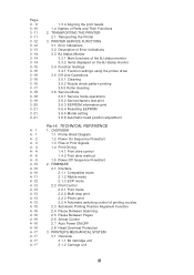
...of the BJ status monitor 3.3.2 Items displayed on the BJ status monitor 3.4 Function Settings 3.4.1 Function settings using the printer driver 3.5 Off-Line Operations 3.5.1 Cleaning 3.5.2 Nozzle check pattern printing 3.5.3 Roller cleaning 3.6 Service Mode 3.6.1 Service mode ... Resetting EEPROM 3.6.5 Model setting 3.6.6 Automatic head position adjustment Part 4: TECHNICAL REFERENCE 1. TRANSPORTING THE PRINTER 2.1 Transporting the Printer 3. OVERVIEW 1.1 Printer Block Diagram 1.2 Power On Sequence Flowchart 1.3 Flow of printing nozzles 2.3 Automatic Printing Position Alignment Function...
...of the BJ status monitor 3.3.2 Items displayed on the BJ status monitor 3.4 Function Settings 3.4.1 Function settings using the printer driver 3.5 Off-Line Operations 3.5.1 Cleaning 3.5.2 Nozzle check pattern printing 3.5.3 Roller cleaning 3.6 Service Mode 3.6.1 Service mode ... Resetting EEPROM 3.6.5 Model setting 3.6.6 Automatic head position adjustment Part 4: TECHNICAL REFERENCE 1. TRANSPORTING THE PRINTER 2.1 Transporting the Printer 3. OVERVIEW 1.1 Printer Block Diagram 1.2 Power On Sequence Flowchart 1.3 Flow of printing nozzles 2.3 Automatic Printing Position Alignment Function...

Service Manual
Page 10
... 11 Control Board and Other Electrical Components Figure 1- 12 How to Disengage a Plastic Hook Part 2: PRODUCT SPECIFICATIONS Figure 2- 1 Printer Appearance Figure 2- 2 Black BJ Cartridge Figure 2- 3 Color BJ Cartridge Figure 2- 4 Photo BJ Cartridge Figure 2- 5 BJ Cartridge Container Figure 2- 6 BJ Cartridges Figure 2- 7 Ink...Figure 3- 12 Operator Panel Figure 3- 13 BJ Status Monitor (Sample) Figure 3- 14 Printer Driver Utility (Sample) Figure 3- 15 Nozzle Check Pattern Print (Sample for Black/Color Cartridge) Figure 3- 16 Service/Factory Test Print Figure 3- 17 EEPROM Information Print (Sample)...
... 11 Control Board and Other Electrical Components Figure 1- 12 How to Disengage a Plastic Hook Part 2: PRODUCT SPECIFICATIONS Figure 2- 1 Printer Appearance Figure 2- 2 Black BJ Cartridge Figure 2- 3 Color BJ Cartridge Figure 2- 4 Photo BJ Cartridge Figure 2- 5 BJ Cartridge Container Figure 2- 6 BJ Cartridges Figure 2- 7 Ink...Figure 3- 12 Operator Panel Figure 3- 13 BJ Status Monitor (Sample) Figure 3- 14 Printer Driver Utility (Sample) Figure 3- 15 Nozzle Check Pattern Print (Sample for Black/Color Cartridge) Figure 3- 16 Service/Factory Test Print Figure 3- 17 EEPROM Information Print (Sample)...
Service Manual
Page 36
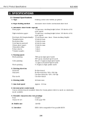
... max. Internal print control mode Canon extended mode (available when the Canon printer driver is used), no emulation mode available 9. stacking height (about 100 sheets of 64 g/m2 paper) High-resolution paper: 10 mm max. Part 2: Product Specifications BJC-6000 2. SPECIFICATIONS 2.1 General Specifications 1. Type Desktop serial color bubble-jet printer 2. Printing speed Black printing: Color printing: Photo printing: 788...
... max. Internal print control mode Canon extended mode (available when the Canon printer driver is used), no emulation mode available 9. stacking height (about 100 sheets of 64 g/m2 paper) High-resolution paper: 10 mm max. Part 2: Product Specifications BJC-6000 2. SPECIFICATIONS 2.1 General Specifications 1. Type Desktop serial color bubble-jet printer 2. Printing speed Black printing: Color printing: Photo printing: 788...
Service Manual
Page 57
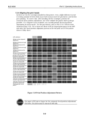
...available, you can still perform the head position adjustment in service mode. Set at least one of the utilities the printer driver package provides. LED calibration 360-dpi vertical alignment adjustment 360-dpi bi-directional rough adjustment 360-dpi bi-directional fine adjustment... procedures, refer to Part 3: 3.6.1 Service mode operations (Page 3-18). To correct this printer, even a slight difference in size or seating position between them may be smeared with ink. 3-9 BJC-6000 Part 3: Operating Instructions 1.3.4 Aligning the print heads As there are two BJ cartridges installed in...
...available, you can still perform the head position adjustment in service mode. Set at least one of the utilities the printer driver package provides. LED calibration 360-dpi vertical alignment adjustment 360-dpi bi-directional rough adjustment 360-dpi bi-directional fine adjustment... procedures, refer to Part 3: 3.6.1 Service mode operations (Page 3-18). To correct this printer, even a slight difference in size or seating position between them may be smeared with ink. 3-9 BJC-6000 Part 3: Operating Instructions 1.3.4 Aligning the print heads As there are two BJ cartridges installed in...
Service Manual
Page 63
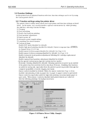
... menu Figure 3-14 Printer Driver Utility (Sample) 3-15 In the menu, you can be set by using the Canon printer driver. 3.4.1 Function settings using the printer driver The printer driver's utility menu allows such operations and function settings as listed below. Enabling this printer has no physical function..., ink smearing of ink on normal plain paper or post cards. BJC-6000 Part 3: Operating Instructions 3.4 Function Settings As this function is useful for saving ink, especially when the printer's power is provided through the computer (possibility of nozzle clogging increases)....
... menu Figure 3-14 Printer Driver Utility (Sample) 3-15 In the menu, you can be set by using the Canon printer driver. 3.4.1 Function settings using the printer driver The printer driver's utility menu allows such operations and function settings as listed below. Enabling this printer has no physical function..., ink smearing of ink on normal plain paper or post cards. BJC-6000 Part 3: Operating Instructions 3.4 Function Settings As this function is useful for saving ink, especially when the printer's power is provided through the computer (possibility of nozzle clogging increases)....
Service Manual
Page 64
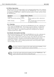
... from either the auto sheet feeder or the manual feed slot, and print a standard pattern using the printer driver utility. 3.5.2 Nozzle check pattern printing With the printer powered on, hold down the RESUME button and after confirming one sheet and powers down. Operations Cleaning Nozzle...16 If five or more cleaning operations fail to solve the problem, replace the BJ cartridge with ink. Part 3: Operating Instructions BJC-6000 3.5 Off-line Operations This printer has three operations which must be of B5 size or larger, from the computer using all nozzles of beeps 1 time 2...
... from either the auto sheet feeder or the manual feed slot, and print a standard pattern using the printer driver utility. 3.5.2 Nozzle check pattern printing With the printer powered on, hold down the RESUME button and after confirming one sheet and powers down. Operations Cleaning Nozzle...16 If five or more cleaning operations fail to solve the problem, replace the BJ cartridge with ink. Part 3: Operating Instructions BJC-6000 3.5 Off-line Operations This printer has three operations which must be of B5 size or larger, from the computer using all nozzles of beeps 1 time 2...
Service Manual
Page 69
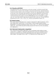
...case, the waste ink absorber must also be initialized. The printer will perform the automatic adjustment in the EEPROM, the Waste Ink Counter must also be replaced with the Black/Color or Photo/Color cartridge, total waste ink absorbed, and the last three ... if the user initiated the adjustment from the computer via the printer driver utility. After setting the model setting, perform the service/factory test printing for different printers. In this printer is necessary to a computer). BJC-6000 Part 3: Operating Instructions 3.6.4 Resetting EEPROM The EEPROM stores such ...
...case, the waste ink absorber must also be initialized. The printer will perform the automatic adjustment in the EEPROM, the Waste Ink Counter must also be replaced with the Black/Color or Photo/Color cartridge, total waste ink absorbed, and the last three ... if the user initiated the adjustment from the computer via the printer driver utility. After setting the model setting, perform the service/factory test printing for different printers. In this printer is necessary to a computer). BJC-6000 Part 3: Operating Instructions 3.6.4 Resetting EEPROM The EEPROM stores such ...
Service Manual
Page 75
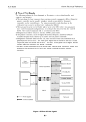
f) The MPU, while controlling the printer controller, control ROM, and motor driver, and monitoring the status of Print Signals 4-3 BJC-6000 Part 4: Technical Reference 1.3 Flow of Print Signals The following outlines the flow of signals as print signal to store ... Board Control ROM : Print Signals : Control Signals MPU f Motor Driver f Sensors Figure 4-3 Flow of the BJ head and printer, controls the entire printing operation. The printer controller sends this data on the control board. e) The printer controller then converts the print data into serial data and sends it...
f) The MPU, while controlling the printer controller, control ROM, and motor driver, and monitoring the status of Print Signals 4-3 BJC-6000 Part 4: Technical Reference 1.3 Flow of Print Signals The following outlines the flow of signals as print signal to store ... Board Control ROM : Print Signals : Control Signals MPU f Motor Driver f Sensors Figure 4-3 Flow of the BJ head and printer, controls the entire printing operation. The printer controller sends this data on the control board. e) The printer controller then converts the print data into serial data and sends it...
Service Manual
Page 88
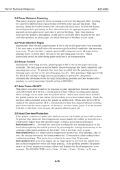
...the problem persists, the printer sees it will be imposed on if more than 20 seconds. Part 4: Technical Reference BJC-6000 2.4 Pause Between Scanning This printer features pause between-scanning to...after ejection, printed paper is detected, the printer sees this , 1-minute pause will only be activated when enabled by differences in characteristics between color ink and black ink. These settings can ...is open . After printing at high speed with the printer driver. Thus, the interface unit is enabled, even if the printer is left for slow-drying print media such as transparencies....
...the problem persists, the printer sees it will be imposed on if more than 20 seconds. Part 4: Technical Reference BJC-6000 2.4 Pause Between Scanning This printer features pause between-scanning to...after ejection, printed paper is detected, the printer sees this , 1-minute pause will only be activated when enabled by differences in characteristics between color ink and black ink. These settings can ...is open . After printing at high speed with the printer driver. Thus, the interface unit is enabled, even if the printer is left for slow-drying print media such as transparencies....
Service Manual
Page 109
...r e SensorTH201 P71 BZ Carriage Board P24 Buzzer IRQ AN6 0~4 RESX HRANK0,1 DIODE0,1 Print Position Sensor Printer Controller PC0 H_D0,1 H_CLOK0,1 HSEL1A0,1 H_RSTX ODD,EVEN HSEL1B0,1 H_LTH BENB0,1 HSEL2A0,1 HSEL2B0,1 DIR HENB0K*5 SUBH0,1 PC3 2 Kbit PB EEPROM 0~3 Driver IC PC1 Paper End Sensor PA1 Error Indicator Power Indicator Home Position Sensor BJ Cartridge... Unit Figure 4-32 Control Unit Function Diagram 4-37 AC Adapter Internal Temperature Sensor A21 Data Bus D0 - BJC-6000 4.2 Control Unit 4.2.1 Control unit block diagram Control Board Address Bus A1 -
...r e SensorTH201 P71 BZ Carriage Board P24 Buzzer IRQ AN6 0~4 RESX HRANK0,1 DIODE0,1 Print Position Sensor Printer Controller PC0 H_D0,1 H_CLOK0,1 HSEL1A0,1 H_RSTX ODD,EVEN HSEL1B0,1 H_LTH BENB0,1 HSEL2A0,1 HSEL2B0,1 DIR HENB0K*5 SUBH0,1 PC3 2 Kbit PB EEPROM 0~3 Driver IC PC1 Paper End Sensor PA1 Error Indicator Power Indicator Home Position Sensor BJ Cartridge... Unit Figure 4-32 Control Unit Function Diagram 4-37 AC Adapter Internal Temperature Sensor A21 Data Bus D0 - BJC-6000 4.2 Control Unit 4.2.1 Control unit block diagram Control Board Address Bus A1 -
Service Manual
Page 110
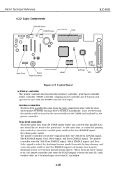
Part 4: Technical Reference 4.2.2 Logic Components CN401 RESUME Switch LED POWER Switch Cover Sensor ROM BJC-6000 CN603 CN402 CN602 CN404 CN403 Motor Driver Printer Controller Buzzer Paper End Sensor DRAM EEPROM MPU TH201 Figure 4-33 Control Board a) Printer controller The printer controller incorporates the interface controller, print head controller, buffer controller, DRAM controller, stepping motor controller and...
Part 4: Technical Reference 4.2.2 Logic Components CN401 RESUME Switch LED POWER Switch Cover Sensor ROM BJC-6000 CN603 CN402 CN602 CN404 CN403 Motor Driver Printer Controller Buzzer Paper End Sensor DRAM EEPROM MPU TH201 Figure 4-33 Control Board a) Printer controller The printer controller incorporates the interface controller, print head controller, buffer controller, DRAM controller, stepping motor controller and...
Service Manual
Page 111
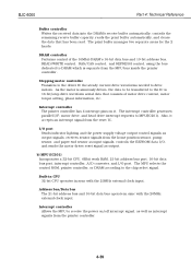
...21-bit address bus and 16-bit data bus operate in sync with the 20MHz external clock input. Stepping motor controller Transfers to the driver IC the steady current drive waveforms needed to the chip select signal. Interrupt controller Allows the MPU to MPU(IC201). b) MPU (IC201...interrupt signal from the MPU bus inside the printer controller. Built-in CPU 32-bit CPU operates in sync with the 20MHz external clock input. I/O port Sends indicator lighting and the power supply voltage output control signals as output. BJC-6000 Part 4: Technical Reference Buffer controller Writes ...
...21-bit address bus and 16-bit data bus operate in sync with the 20MHz external clock input. Stepping motor controller Transfers to the driver IC the steady current drive waveforms needed to the chip select signal. Interrupt controller Allows the MPU to MPU(IC201). b) MPU (IC201...interrupt signal from the MPU bus inside the printer controller. Built-in CPU 32-bit CPU operates in sync with the 20MHz external clock input. I/O port Sends indicator lighting and the power supply voltage output control signals as output. BJC-6000 Part 4: Technical Reference Buffer controller Writes ...
Service Manual
Page 112
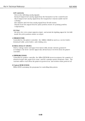
...Receives the cover sensor signal as input, and sends the lighting signal for the LED inside the BJ cartridge. d) Motor driver IC (IC401) Drives carriage motor and paper feed motor with steady currents generated according to the drive current signal data (...the printer is used as output. Head temperature analog signal from the temperature sensors inside the print position sensor as a receive buffer, download buffer, print buffer, and working area. f) Control ROM (IC202) 8Mbit ROM containing the programs for printing position compensation. Part 4: Technical Reference BJC-6000 A/D...
...Receives the cover sensor signal as input, and sends the lighting signal for the LED inside the BJ cartridge. d) Motor driver IC (IC401) Drives carriage motor and paper feed motor with steady currents generated according to the drive current signal data (...the printer is used as output. Head temperature analog signal from the temperature sensors inside the print position sensor as a receive buffer, download buffer, print buffer, and working area. f) Control ROM (IC202) 8Mbit ROM containing the programs for printing position compensation. Part 4: Technical Reference BJC-6000 A/D...
Service Manual
Page 113
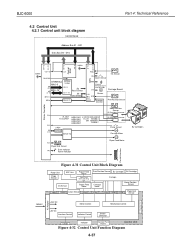
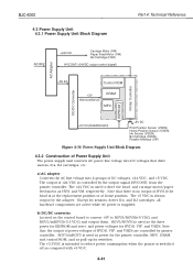
... that the output of power voltages of HVDD, VIF, and VSEN are active while AC power is controlled by the output signal (HVCONT) from the printer controller. BJC-6000 4.3 Power Supply Unit 4.3.1 Power Supply Unit Block Diagram Part 4: Technical Reference AC100V +24V DC Carriage Motor (VM) Paper Feed Motor (VM) BJ Cartridge (HVH... of DC voltages, +24 VDC, and +5 VDC. RGV5/RGV5I is switched off as the drive power for EEPROM and reset, and power voltages for sensors, driver ICs, and BJ cartridges, all hardware components are controlled by...
... that the output of power voltages of HVDD, VIF, and VSEN are active while AC power is controlled by the output signal (HVCONT) from the printer controller. BJC-6000 4.3 Power Supply Unit 4.3.1 Power Supply Unit Block Diagram Part 4: Technical Reference AC100V +24V DC Carriage Motor (VM) Paper Feed Motor (VM) BJ Cartridge (HVH... of DC voltages, +24 VDC, and +5 VDC. RGV5/RGV5I is switched off as the drive power for EEPROM and reset, and power voltages for sensors, driver ICs, and BJ cartridges, all hardware components are controlled by...


