A7V600-X User's manual
Page 11
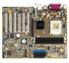
Motherboard Info ASUS A7V600-X motherboard 1-1 Chapter 1 This chapter gives information about the ASUS A7V600-X motherboard that came with the system.This chapter includes the motherboard layout, jumper settings, and connector locations.
Motherboard Info ASUS A7V600-X motherboard 1-1 Chapter 1 This chapter gives information about the ASUS A7V600-X motherboard that came with the system.This chapter includes the motherboard layout, jumper settings, and connector locations.
A7V600-X User's manual
Page 12
... package with the list below. 1.2 Package contents Check your ASUS A7V600-X package for the following items. ASUS A7V600-X motherboard ATX form factor: 12 in x 9.6 in a motherboard. 1.1 Welcome! Before you for socket A processors. Unique ASUS features such as 6-channel audio, Fast Ethernet LAN and S/PDIF out features. The ASUS A7V600-X motherboard is loaded with FSB 400 and DDR 400 support, the...
... package with the list below. 1.2 Package contents Check your ASUS A7V600-X package for the following items. ASUS A7V600-X motherboard ATX form factor: 12 in x 9.6 in a motherboard. 1.1 Welcome! Before you for socket A processors. Unique ASUS features such as 6-channel audio, Fast Ethernet LAN and S/PDIF out features. The ASUS A7V600-X motherboard is loaded with FSB 400 and DDR 400 support, the...
A7V600-X User's manual
Page 13
.... Based on the advanced VIA KT600 chipset with FSB 400 and DDR 400 support, the ASUS A7V600-X features AGP8X, Serial ATA, USB 2.0 as well as ASUS C.O.P., C.P.R. Visit the ASUS website for the latest qualified DDR400 module list.) AGP 8X support AGP 8X (AGP 3.0) ... enhanced graphics performance with high bandwidth speeds up to 2.12 GB/s. ASUS A7V600-X motherboard 1-3 With a bus of devices such as AGP 4X. 1.3 Special features 1.3.1 Product highlights 400 FSB K7 Platform The ASUS A7V600-X motherboard is loaded with the most advanced technologies to deliver the maximum performance...
.... Based on the advanced VIA KT600 chipset with FSB 400 and DDR 400 support, the ASUS A7V600-X features AGP8X, Serial ATA, USB 2.0 as well as ASUS C.O.P., C.P.R. Visit the ASUS website for the latest qualified DDR400 module list.) AGP 8X support AGP 8X (AGP 3.0) ... enhanced graphics performance with high bandwidth speeds up to 2.12 GB/s. ASUS A7V600-X motherboard 1-3 With a bus of devices such as AGP 4X. 1.3 Special features 1.3.1 Product highlights 400 FSB K7 Platform The ASUS A7V600-X motherboard is loaded with the most advanced technologies to deliver the maximum performance...
A7V600-X User's manual
Page 15
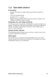
...-tuning system bus frequency from 100MHz up to ensure stable supply of current for critical components. ASUS A7V600-X motherboard 1-5 Connect to the Internet then to the ASUS FTP site nearest you to obtain the latest BIOS version for your motherboard. The system voltage levels are monitored to 250MHz at 1MHz increments Temperature, fan, and voltage...
...-tuning system bus frequency from 100MHz up to ensure stable supply of current for critical components. ASUS A7V600-X motherboard 1-5 Connect to the Internet then to the ASUS FTP site nearest you to obtain the latest BIOS version for your motherboard. The system voltage levels are monitored to 250MHz at 1MHz increments Temperature, fan, and voltage...
A7V600-X User's manual
Page 17
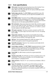
...pin DIMM sockets support up to four Ultra DMA133/100/66, PIO Modes 3 & 4 IDE devices. ASUS A7V600-X Motherboard 1-7 One side of the connector is only at least 1A on the motherboard. This LED acts as a reminder to an ATX +12V power supply. The chipset supports a highperformance ...9 South bridge controller. These two 7-pin connectors accommodate the thin cables for 3D graphical applications. 8 Serial ATA connectors. Visit the ASUS website (www.asus.com) for the AMD Athlon XP/Athlon/Duron Processors. (Note: When using unbuffered non-ECC PC2700/2100 DDR DIMMs. (Note: PC3200...
...pin DIMM sockets support up to four Ultra DMA133/100/66, PIO Modes 3 & 4 IDE devices. ASUS A7V600-X Motherboard 1-7 One side of the connector is only at least 1A on the motherboard. This LED acts as a reminder to an ATX +12V power supply. The chipset supports a highperformance ...9 South bridge controller. These two 7-pin connectors accommodate the thin cables for 3D graphical applications. 8 Serial ATA connectors. Visit the ASUS website (www.asus.com) for the AMD Athlon XP/Athlon/Duron Processors. (Note: When using unbuffered non-ECC PC2700/2100 DDR DIMMs. (Note: PC3200...
A7V600-X User's manual
Page 19
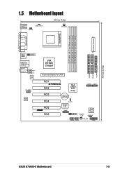
PRI_IDE SEC_IDE FLOPPY 30.5cm (12.0in) 1.5 Motherboard layout PS/2KBMS T: Mouse B: Keyboard KBPWR OVER_VOLT1 24.5cm (9.6in) CPU_FAN SPDIF_O ATX Power Connector Socket 462 DDR DIMM1 (64/72 bit,184-pin module) ... In AUX CD 10/100 LAN FP_AUDIO AD1980 CODEC VIA KT600 Chipset Accelerated Graphics Port (AGP) PCI1 A7V600-X PCI2 VIA VT8237 South Bridge SATA2 SATA1 PCI3 CR2032 3V Lithium Cell CMOS Power PCI4 PCI5 ® PCI6 CLRTC Super I/O GAME USBPW78 USBPW56 SB_PWR 4Mbit Low Pin Count CHASSIS USB56 USB78 CHA_FAN PANEL ASUS A7V600-X Motherboard 1-9
PRI_IDE SEC_IDE FLOPPY 30.5cm (12.0in) 1.5 Motherboard layout PS/2KBMS T: Mouse B: Keyboard KBPWR OVER_VOLT1 24.5cm (9.6in) CPU_FAN SPDIF_O ATX Power Connector Socket 462 DDR DIMM1 (64/72 bit,184-pin module) ... In AUX CD 10/100 LAN FP_AUDIO AD1980 CODEC VIA KT600 Chipset Accelerated Graphics Port (AGP) PCI1 A7V600-X PCI2 VIA VT8237 South Bridge SATA2 SATA1 PCI3 CR2032 3V Lithium Cell CMOS Power PCI4 PCI5 ® PCI6 CLRTC Super I/O GAME USBPW78 USBPW56 SB_PWR 4Mbit Low Pin Count CHASSIS USB56 USB78 CHA_FAN PANEL ASUS A7V600-X Motherboard 1-9

A7V600-X User's manual
Page 21
... not overtighten the screws! The edge with external ports goes to the rear part of the chassis ASUS A7V600-X Motherboard 1-11 The motherboard uses the ATX form factor that the motherboard fits into it into the chassis in the image below. 1.7.2 Screw holes Place nine (9) screws into the holes ...indicated by circles to secure the motherboard to unplug the power cord before installing or removing the motherboard. Place this side towards the rear of the chassis as indicated in the correct orientation. Doing so may...
... not overtighten the screws! The edge with external ports goes to the rear part of the chassis ASUS A7V600-X Motherboard 1-11 The motherboard uses the ATX form factor that the motherboard fits into it into the chassis in the image below. 1.7.2 Screw holes Place nine (9) screws into the holes ...indicated by circles to secure the motherboard to unplug the power cord before installing or removing the motherboard. Place this side towards the rear of the chassis as indicated in the correct orientation. Doing so may...
A7V600-X User's manual
Page 23
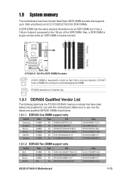
... sure to avoid damaging the DIMM. DIMM1 DIMM2 DIMM3 104 Pins 80 Pins A7V600-X ® A7V600-X 184-Pin DDR DIMM Sockets A DDR DIMM is double notched. PC3200 maximum to the 168-pin of the SDR DIMM. 1.9 System memory The motherboard has three Double Data Rate (DDR) DIMM sockets that supports up to 3GB... 512MB 512MB 256MB 256 Type DS DS SS SS P/N MAG16UL3264D1TG5A-KC MT16VDDT6464AG-40BC4 NT256D64S88B1G-5T MDOSS6F3G31JB1EAE Chip GL3LC32G88TG-5A MT46V32M8TG-5BC NT5DS32M8BT-5T K4H560838D-TCC4 ASUS A7V600-X Motherboard 1-13
... sure to avoid damaging the DIMM. DIMM1 DIMM2 DIMM3 104 Pins 80 Pins A7V600-X ® A7V600-X 184-Pin DDR DIMM Sockets A DDR DIMM is double notched. PC3200 maximum to the 168-pin of the SDR DIMM. 1.9 System memory The motherboard has three Double Data Rate (DDR) DIMM sockets that supports up to 3GB... 512MB 512MB 256MB 256 Type DS DS SS SS P/N MAG16UL3264D1TG5A-KC MT16VDDT6464AG-40BC4 NT256D64S88B1G-5T MDOSS6F3G31JB1EAE Chip GL3LC32G88TG-5A MT46V32M8TG-5BC NT5DS32M8BT-5T K4H560838D-TCC4 ASUS A7V600-X Motherboard 1-13
A7V600-X User's manual
Page 24
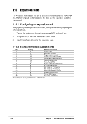
... installing the expansion card, configure the card by adjusting the software settings. 1. Assign an IRQ to the tables below. 3. 1.10 Expansion slots The A7V600-X motherboard has six (6) expansion PCI slots and one (1) AGP 8X slot. Install the software drivers for the expansion card. 1.10.2 Standard Interrupt Assignments IRQ...Processor 14* 9 Primary IDE Channel 15* 10 Secondary IDE Channel *These IRQs are usually available for ISA or PCI devices. 1-14 Chapter 1: Motherboard Information Refer to the card. Turn on the system and change the necessary BIOS settings, if any. 2.
... installing the expansion card, configure the card by adjusting the software settings. 1. Assign an IRQ to the tables below. 3. 1.10 Expansion slots The A7V600-X motherboard has six (6) expansion PCI slots and one (1) AGP 8X slot. Install the software drivers for the expansion card. 1.10.2 Standard Interrupt Assignments IRQ...Processor 14* 9 Primary IDE Channel 15* 10 Secondary IDE Channel *These IRQs are usually available for ISA or PCI devices. 1-14 Chapter 1: Motherboard Information Refer to the card. Turn on the system and change the necessary BIOS settings, if any. 2.
A7V600-X User's manual
Page 25
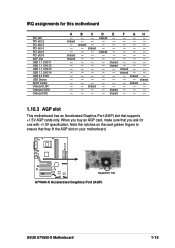
IRQ assignments for 1.5v ® A7V600-X Accelerated Graphics Port (AGP) ASUS A7V600-X Motherboard 1-15 shared shared BC -- -- When you buy an AGP card, make sure that they fit the AGP slot on your motherboard. shared - - shared shared -- -- D shared - - - shared E shared shared shared shared F GH shared - -... - - - shared - - - Note the notches on the card golden fingers to ensure that you ask for one with +1.5V specification. A7V600-X Keyed for this motherboard PCI slot PCI slot 2 PCI slot 3 PCI slot 4 PCI slot 5 PCI slot 6 AGP slot USB 1.1 UHCI 1 USB 1.1 UHCI ...
IRQ assignments for 1.5v ® A7V600-X Accelerated Graphics Port (AGP) ASUS A7V600-X Motherboard 1-15 shared shared BC -- -- When you buy an AGP card, make sure that they fit the AGP slot on your motherboard. shared - - shared shared -- -- D shared - - - shared E shared shared shared shared F GH shared - -... - - - shared - - - Note the notches on the card golden fingers to ensure that you ask for one with +1.5V specification. A7V600-X Keyed for this motherboard PCI slot PCI slot 2 PCI slot 3 PCI slot 4 PCI slot 5 PCI slot 6 AGP slot USB 1.1 UHCI 1 USB 1.1 UHCI ...
A7V600-X User's manual
Page 27
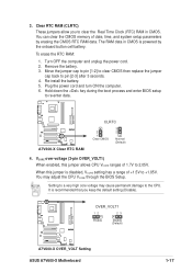
... date, time, and system setup parameters by the onboard button cell battery. Re-install the battery. 5. A7V600-X ® A7V600-X Clear RTC RAM CLRTC 2 1 Clear CMOS 3 2 Normal (Default) 4. A7V600-X OVER_VOLT1 12 23 Enable Disable (Default) ® A7V600-X OVER_VOLT Setting ASUS A7V600-X Motherboard 1-17 Move the jumper cap to pin [1-2] to clear CMOS then replace the jumper cap back...
... date, time, and system setup parameters by the onboard button cell battery. Re-install the battery. 5. A7V600-X ® A7V600-X Clear RTC RAM CLRTC 2 1 Clear CMOS 3 2 Normal (Default) 4. A7V600-X OVER_VOLT1 12 23 Enable Disable (Default) ® A7V600-X OVER_VOLT Setting ASUS A7V600-X Motherboard 1-17 Move the jumper cap to pin [1-2] to clear CMOS then replace the jumper cap back...

A7V600-X User's manual
Page 29
... prevent incorrect insertion when using ribbon cables with intrusion detection feature. CHASSIS +5VSB_MB Chassis Signal GND A7V600-X ® A7V600-X Chassis Alarm Lead (Default) ASUS A7V600-X Motherboard 1-19 Chassis intrusion connector (4-1 pin CHASSIS) This lead is removed to record a chassis intrusion ...event. After connecting one end to the motherboard, connect the other end to the floppy drive. (Pin 5 is for a chassis...
... prevent incorrect insertion when using ribbon cables with intrusion detection feature. CHASSIS +5VSB_MB Chassis Signal GND A7V600-X ® A7V600-X Chassis Alarm Lead (Default) ASUS A7V600-X Motherboard 1-19 Chassis intrusion connector (4-1 pin CHASSIS) This lead is removed to record a chassis intrusion ...event. After connecting one end to the motherboard, connect the other end to the floppy drive. (Pin 5 is for a chassis...
A7V600-X User's manual
Page 31
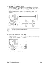
USB+5V USB_P8USB_P8+ GND NC USB+5V USB_P6USB_P6+ GND NC USB+5V USB_P7USB_P7+ GND A7V600-X ® A7V600-X USB 2.0 Header USB56 1 USB78 1 USB+5V USB_P5USB_P5+ GND The USB 2.0 module is available for additional USB ports. The USB header ... Mbps on the rear panel are inadequate, a USB header is purchased separately. 7. Right Audio Channel Ground Ground Left Audio Channel A7V600-X ® AUX(White) CD(Black) A7V600-X Internal Audio Connectors ASUS A7V600-X Motherboard 1-21 6. USB header (4-1 pin USB56, USB78) If the USB ports on USB 1.1. Connect a USB 2.0 module to this...
USB+5V USB_P8USB_P8+ GND NC USB+5V USB_P6USB_P6+ GND NC USB+5V USB_P7USB_P7+ GND A7V600-X ® A7V600-X USB 2.0 Header USB56 1 USB78 1 USB+5V USB_P5USB_P5+ GND The USB 2.0 module is available for additional USB ports. The USB header ... Mbps on the rear panel are inadequate, a USB header is purchased separately. 7. Right Audio Channel Ground Ground Left Audio Channel A7V600-X ® AUX(White) CD(Black) A7V600-X Internal Audio Connectors ASUS A7V600-X Motherboard 1-21 6. USB header (4-1 pin USB56, USB78) If the USB ports on USB 1.1. Connect a USB 2.0 module to this...

A7V600-X User's manual
Page 33
...the case-mounted speaker and allows you turn on the system power, and blinks when the system is purchased separately. ASUS A7V600-X Motherboard 1-23 A7V600-X SATA2 ® A7V600-X SATA Connectors The SATA cable is in sleep mode. • System Warning Speaker Lead (4-pin SPKR) This ...4-pin connector connects to hear system beeps and warnings. ExtSMI# Ground PWR Ground Reset Ground A7V600-X Reset SW IDE_LED ATX Power ® SMI Lead Switch* * Requires an ATX power supply. A7V600-X System Panel Connectors • System Power LED Lead (3-1 pin PLED) This 3-1 pin ...
...the case-mounted speaker and allows you turn on the system power, and blinks when the system is purchased separately. ASUS A7V600-X Motherboard 1-23 A7V600-X SATA2 ® A7V600-X SATA Connectors The SATA cable is in sleep mode. • System Warning Speaker Lead (4-pin SPKR) This ...4-pin connector connects to hear system beeps and warnings. ExtSMI# Ground PWR Ground Reset Ground A7V600-X Reset SW IDE_LED ATX Power ® SMI Lead Switch* * Requires an ATX power supply. A7V600-X System Panel Connectors • System Power LED Lead (3-1 pin PLED) This 3-1 pin ...
A7V600-X User's manual
Page 35
BIOS Information ASUS A7V600-X motherboard 2-1 Detailed descriptions of the BIOS parameters are also provided. Chapter 2 This chapter tells how to change the system settings through the BIOS setup menus.
BIOS Information ASUS A7V600-X motherboard 2-1 Detailed descriptions of the BIOS parameters are also provided. Chapter 2 This chapter tells how to change the system settings through the BIOS setup menus.
A7V600-X User's manual
Page 37
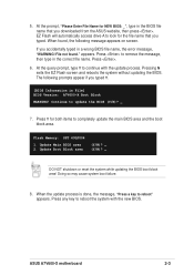
...(Y/N)? _ DO NOT shutdown or reset the system while updating the BIOS boot block area! appears. Flash Memory: SST 49LF004 1. ASUS A7V600-X motherboard 2-3 5. If you downloaded from the ASUS website, then press . Press . 6. At the query prompt, type Y to remove the message, then type in the BIOS... the update process. The following message appears on screen. Press Y for the file name that you accidentally typed in File] BIOS Version: A7V600-X Boot Block WARNING! Doing so may cause system boot failure. 8. When the update process is done, the message, "Press a key ...
...(Y/N)? _ DO NOT shutdown or reset the system while updating the BIOS boot block area! appears. Flash Memory: SST 49LF004 1. ASUS A7V600-X motherboard 2-3 5. If you downloaded from the ASUS website, then press . Press . 6. At the query prompt, type Y to remove the message, then type in the BIOS... the update process. The following message appears on screen. Press Y for the file name that you accidentally typed in File] BIOS Version: A7V600-X Boot Block WARNING! Doing so may cause system boot failure. 8. When the update process is done, the message, "Press a key ...
A7V600-X User's manual
Page 39
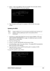
...then press . Type the filename of your problems. Careless updating may result to more problems with the motherboard! 1. Type a filename and the path, for example, A:\XXX- ASUS A7V600-X motherboard 2-5 Updating the BIOS Update the BIOS only if you created earlier. 2. Download an updated... ASUS BIOS file from the Internet (WWW or FTP) (see ASUS CONTACT INFORMATION on page x for details) and save to File from the...
...then press . Type the filename of your problems. Careless updating may result to more problems with the motherboard! 1. Type a filename and the path, for example, A:\XXX- ASUS A7V600-X motherboard 2-5 Updating the BIOS Update the BIOS only if you created earlier. 2. Download an updated... ASUS BIOS file from the Internet (WWW or FTP) (see ASUS CONTACT INFORMATION on page x for details) and save to File from the...
A7V600-X User's manual
Page 41
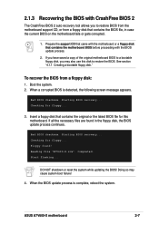
... the necessary files are found ! Checking for floppy... 3. Start flashing... Doing so may also use this motherboard. When a corrupted BIOS is complete, reboot the system. Checking for floppy... See section "4.1.1 Creating a ...A7V600-X.rom". If you have saved a copy of the original motherboard BIOS to a bootable floppy disk, you to restore the BIOS. Insert a floppy disk that contains the motherboard BIOS before proceeding with CrashFree BIOS 2 The CrashFree BIOS 2 auto recovery tool allows you may cause system boot failure! 4. Completed. ASUS A7V600-X motherboard...
... the necessary files are found ! Checking for floppy... 3. Start flashing... Doing so may also use this motherboard. When a corrupted BIOS is complete, reboot the system. Checking for floppy... See section "4.1.1 Creating a ...A7V600-X.rom". If you have saved a copy of the original motherboard BIOS to a bootable floppy disk, you to restore the BIOS. Insert a floppy disk that contains the motherboard BIOS before proceeding with CrashFree BIOS 2 The CrashFree BIOS 2 auto recovery tool allows you may cause system boot failure! 4. Completed. ASUS A7V600-X motherboard...

A7V600-X User's manual
Page 43
...menu or to use as possible. Because the BIOS software is designed to make changes to reconfigure your selections among the predetermined choices. ASUS A7V600-X motherboard 2-9 This requires you see on your computer in the CMOS RAM of the EEPROM. When you start up the computer, the system...opportunity to run this menu to configure the default system device used to the power management settings. Even if you are installing a motherboard, reconfiguring your system using the BIOS Setup program so that the computer can scroll through the various sub-menus and make changes ...
...menu or to use as possible. Because the BIOS software is designed to make changes to reconfigure your selections among the predetermined choices. ASUS A7V600-X motherboard 2-9 This requires you see on your computer in the CMOS RAM of the EEPROM. When you start up the computer, the system...opportunity to run this menu to configure the default system device used to the power management settings. Even if you are installing a motherboard, reconfiguring your system using the BIOS Setup program so that the computer can scroll through the various sub-menus and make changes ...
A7V600-X User's manual
Page 45
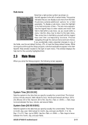
... to the left of certain fields. The format is hour, minute, second. Use the or + keys to move between the month, day, and year fields. ASUS A7V600-X motherboard 2-11 Use the legend keys to enter values and move the highlight to the field and press . Use the or + keys to move between the...
... to the left of certain fields. The format is hour, minute, second. Use the or + keys to move between the month, day, and year fields. ASUS A7V600-X motherboard 2-11 Use the legend keys to enter values and move the highlight to the field and press . Use the or + keys to move between the...


