
A7V600-X User's manual
Page 1
Motherboard A7V600-X User Guide
Motherboard A7V600-X User Guide
A7V600-X User's manual
Page 3
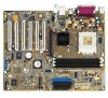
Features Contents Notices v Safety information vi About this guide vii ASUS contact information viii A7V600-X specifications summary ix Chapter 1: Product introduction 1.1 Welcome 1-2 1.2 Package contents 1-2 1.3 Special Features 1-3 1.3.1 Product highlights 1-3 1.3.2 Value-added solutions 1-5 1.4 Motherboard components 1-6 1.4.1 Core specifications 1-7 1.5 Motherboard layout 1-9 1.6 Before you proceed 1-10 1.7 Motherboard installation 1-11 1.7.1 Placement direction 1-11 1.7.2 Screw holes 1-11 1.8 Central Processing Unit (CPU 1-12 1.8.1 Installing...
Features Contents Notices v Safety information vi About this guide vii ASUS contact information viii A7V600-X specifications summary ix Chapter 1: Product introduction 1.1 Welcome 1-2 1.2 Package contents 1-2 1.3 Special Features 1-3 1.3.1 Product highlights 1-3 1.3.2 Value-added solutions 1-5 1.4 Motherboard components 1-6 1.4.1 Core specifications 1-7 1.5 Motherboard layout 1-9 1.6 Before you proceed 1-10 1.7 Motherboard installation 1-11 1.7.1 Placement direction 1-11 1.7.2 Screw holes 1-11 1.8 Central Processing Unit (CPU 1-12 1.8.1 Installing...
A7V600-X User's manual
Page 11
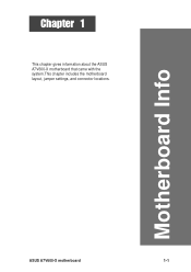
Chapter 1 This chapter gives information about the ASUS A7V600-X motherboard that came with the system.This chapter includes the motherboard layout, jumper settings, and connector locations. Motherboard Info ASUS A7V600-X motherboard 1-1
Chapter 1 This chapter gives information about the ASUS A7V600-X motherboard that came with the system.This chapter includes the motherboard layout, jumper settings, and connector locations. Motherboard Info ASUS A7V600-X motherboard 1-1
A7V600-X User's manual
Page 12
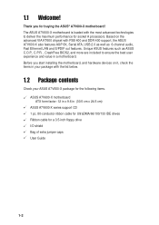
...the ASUS® A7V600-X motherboard! Based on it, check the items in a motherboard. Before you for socket A processors. The ASUS A7V600-X motherboard is loaded with the most advanced technologies to ensure the best user experience and value in your ASUS A7V600-X package for the following items. ASUS A7V600-X motherboard ATX... form factor: 12 in x 9.6 in (30.5 cm x 24.5 cm) ASUS A7V600-X series support CD 1 pc. 80-conductor ribbon cable for ...
...the ASUS® A7V600-X motherboard! Based on it, check the items in a motherboard. Before you for socket A processors. The ASUS A7V600-X motherboard is loaded with the most advanced technologies to ensure the best user experience and value in your ASUS A7V600-X package for the following items. ASUS A7V600-X motherboard ATX... form factor: 12 in x 9.6 in (30.5 cm x 24.5 cm) ASUS A7V600-X series support CD 1 pc. 80-conductor ribbon cable for ...
A7V600-X User's manual
Page 13
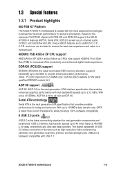
... for socket A processors. 1.3 Special features 1.3.1 Product highlights 400 FSB K7 Platform The ASUS A7V600-X motherboard is loaded with the most advanced technologies to ensure the best user experience and value in a motherboard. 400MHz FSB Athlon XP CPU support AMD's Athlon XP 3200+ and all follow-up... CPUs now support 400MHz Front Side Bus (FSB) for increased office productivity and enhanced digital media experience. ASUS A7V600-X motherboard 1-3 DDR400 (PC3200) support DDR400 (PC3200), the latest and fastest DDR memory standard, supports bandwidth up to 2 DIMMs only. Visit the...
... for socket A processors. 1.3 Special features 1.3.1 Product highlights 400 FSB K7 Platform The ASUS A7V600-X motherboard is loaded with the most advanced technologies to ensure the best user experience and value in a motherboard. 400MHz FSB Athlon XP CPU support AMD's Athlon XP 3200+ and all follow-up... CPUs now support 400MHz Front Side Bus (FSB) for increased office productivity and enhanced digital media experience. ASUS A7V600-X motherboard 1-3 DDR400 (PC3200) support DDR400 (PC3200), the latest and fastest DDR memory standard, supports bandwidth up to 2 DIMMs only. Visit the...
A7V600-X User's manual
Page 14
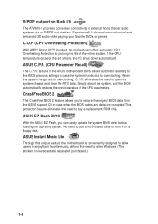
... to prolong the life of the ASUS motherboard BIOS allows automatic resetting to the BIOS previous settings in case when the BIOS codes and data are separately purchased.) 1-4 feature of the entire system. ASUS EZ Flash BIOS With the ASUS EZ Flash, you to open the...Windows. (The stickers on Back I/O The A7V600-X provides convenient connectivity to overclocking. Simply reboot the system, and the BIOS automatically restores the previous value of the CPU parameters. ASUS Instant Music Lite Through this unique feature, the motherboard is conveniently designed to allow users to enjoy...
... to prolong the life of the ASUS motherboard BIOS allows automatic resetting to the BIOS previous settings in case when the BIOS codes and data are separately purchased.) 1-4 feature of the entire system. ASUS EZ Flash BIOS With the ASUS EZ Flash, you to open the...Windows. (The stickers on Back I/O The A7V600-X provides convenient connectivity to overclocking. Simply reboot the system, and the BIOS automatically restores the previous value of the CPU parameters. ASUS Instant Music Lite Through this unique feature, the motherboard is conveniently designed to allow users to enjoy...
A7V600-X User's manual
Page 15
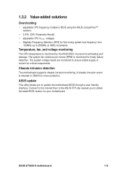
... to 250MHz at 1MHz increments Temperature, fan, and voltage monitoring The CPU temperature is monitored for your motherboard. ASUS A7V600-X motherboard 1-5 Connect to the Internet then to the ASUS FTP site nearest you to prevent overheating and damage. ASUS update This utility allows you to ensure stable supply of current for critical components. Chassis intrusion detection...
... to 250MHz at 1MHz increments Temperature, fan, and voltage monitoring The CPU temperature is monitored for your motherboard. ASUS A7V600-X motherboard 1-5 Connect to the Internet then to the ASUS FTP site nearest you to prevent overheating and damage. ASUS update This utility allows you to ensure stable supply of current for critical components. Chassis intrusion detection...
A7V600-X User's manual
Page 17
...up to 3GB system memory using CPUs with FSB 100, the maximum DDR data transfer rate allowed is only at least 1A on the motherboard. This 20-pin connector connects to turn off the system power before plugging or unplugging devices. 12 USB connectors. These two 7-pin ...bus master IDE controller, up if there is slotted to 2 DIMMs support only. This LED acts as a reminder to an ATX +12V power supply. ASUS A7V600-X Motherboard 1-7 This LED lights up to prevent incorrect insertion of the connector is a standby power on the +5V standby lead (+5VSB). 6 Floppy disk connector....
...up to 3GB system memory using CPUs with FSB 100, the maximum DDR data transfer rate allowed is only at least 1A on the motherboard. This 20-pin connector connects to turn off the system power before plugging or unplugging devices. 12 USB connectors. These two 7-pin ...bus master IDE controller, up if there is slotted to 2 DIMMs support only. This LED acts as a reminder to an ATX +12V power supply. ASUS A7V600-X Motherboard 1-7 This LED lights up to prevent incorrect insertion of the connector is a standby power on the +5V standby lead (+5VSB). 6 Floppy disk connector....
A7V600-X User's manual
Page 19
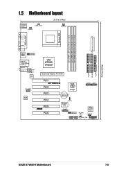
PRI_IDE SEC_IDE FLOPPY 30.5cm (12.0in) 1.5 Motherboard layout PS/2KBMS T: Mouse B: Keyboard KBPWR OVER_VOLT1 24.5cm (9.6in) CPU_FAN SPDIF_O ATX Power Connector Socket 462 DDR DIMM1 (64/72 bit,184-pin module) ... In AUX CD 10/100 LAN FP_AUDIO AD1980 CODEC VIA KT600 Chipset Accelerated Graphics Port (AGP) PCI1 A7V600-X PCI2 VIA VT8237 South Bridge SATA2 SATA1 PCI3 CR2032 3V Lithium Cell CMOS Power PCI4 PCI5 ® PCI6 CLRTC Super I/O GAME USBPW78 USBPW56 SB_PWR 4Mbit Low Pin Count CHASSIS USB56 USB78 CHA_FAN PANEL ASUS A7V600-X Motherboard 1-9
PRI_IDE SEC_IDE FLOPPY 30.5cm (12.0in) 1.5 Motherboard layout PS/2KBMS T: Mouse B: Keyboard KBPWR OVER_VOLT1 24.5cm (9.6in) CPU_FAN SPDIF_O ATX Power Connector Socket 462 DDR DIMM1 (64/72 bit,184-pin module) ... In AUX CD 10/100 LAN FP_AUDIO AD1980 CODEC VIA KT600 Chipset Accelerated Graphics Port (AGP) PCI1 A7V600-X PCI2 VIA VT8237 South Bridge SATA2 SATA1 PCI3 CR2032 3V Lithium Cell CMOS Power PCI4 PCI5 ® PCI6 CLRTC Super I/O GAME USBPW78 USBPW56 SB_PWR 4Mbit Low Pin Count CHASSIS USB56 USB78 CHA_FAN PANEL ASUS A7V600-X Motherboard 1-9
A7V600-X User's manual
Page 20
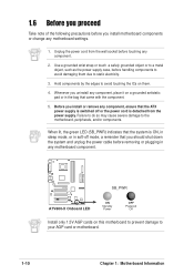
...to avoid damaging them . 4. When lit, the green LED (SB_PWR) indicates that the system is detached from the wall socket before touching any motherboard settings. 1. Use a grounded wrist strap or touch a safely grounded object or to a metal object, such as the power supply case, ... any component. 2. Failure to do so may cause severe damage to your AGP card or motherboard. 1-10 Chapter 1: Motherboard Information Unplug the power cord from the power supply. A7V600-X SB_PWR ® A7V600-X Onboard LED ON Standby Power OFF Powered Off Install only 1.5V AGP cards on a grounded...
...to avoid damaging them . 4. When lit, the green LED (SB_PWR) indicates that the system is detached from the wall socket before touching any motherboard settings. 1. Use a grounded wrist strap or touch a safely grounded object or to a metal object, such as the power supply case, ... any component. 2. Failure to do so may cause severe damage to your AGP card or motherboard. 1-10 Chapter 1: Motherboard Information Unplug the power cord from the power supply. A7V600-X SB_PWR ® A7V600-X Onboard LED ON Standby Power OFF Powered Off Install only 1.5V AGP cards on a grounded...

A7V600-X User's manual
Page 21
... holes Place nine (9) screws into the holes indicated by circles to secure the motherboard to the chassis. Failure to do so may damage the motherboard. Do not overtighten the screws! The edge with external ports goes to the ...the power cord before installing or removing the motherboard. Doing so may cause you physical injury and damage motherboard components. 1.7.1 Placement direction When installing the motherboard, make sure that you install the motherboard, study the configuration of the chassis ASUS A7V600-X Motherboard 1-11 1.7 Motherboard installation Before you place it .
... holes Place nine (9) screws into the holes indicated by circles to secure the motherboard to the chassis. Failure to do so may damage the motherboard. Do not overtighten the screws! The edge with external ports goes to the ...the power cord before installing or removing the motherboard. Doing so may cause you physical injury and damage motherboard components. 1.7.1 Placement direction When installing the motherboard, make sure that you install the motherboard, study the configuration of the chassis ASUS A7V600-X Motherboard 1-11 1.7 Motherboard installation Before you place it .
A7V600-X User's manual
Page 22
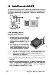
...; CPU CPU NOTCH TO INNER CORNER ® A7V600-X Socket A CPU NOTCH LEVER LOCK 1.8.1 Installing the CPU Follow these steps to support all the latest computing ...the socket base. Locate the Socket 462 and open it snaps shut. 5. 1.8 Central Processing Unit (CPU) The motherboard provides a Socket A (462) for bent pins. 4. The A7V600-X supports AthlonTM XP, AMD AthlonTM, AMD Barton™ and AMD DuronTM processors. Do not force the CPU into place...from the socket. Carefully attach the heatsink locking brace to keep the CPU in place 1-12 Chapter 1: Motherboard Information
...; CPU CPU NOTCH TO INNER CORNER ® A7V600-X Socket A CPU NOTCH LEVER LOCK 1.8.1 Installing the CPU Follow these steps to support all the latest computing ...the socket base. Locate the Socket 462 and open it snaps shut. 5. 1.8 Central Processing Unit (CPU) The motherboard provides a Socket A (462) for bent pins. 4. The A7V600-X supports AthlonTM XP, AMD AthlonTM, AMD Barton™ and AMD DuronTM processors. Do not force the CPU into place...from the socket. Carefully attach the heatsink locking brace to keep the CPU in place 1-12 Chapter 1: Motherboard Information
A7V600-X User's manual
Page 23
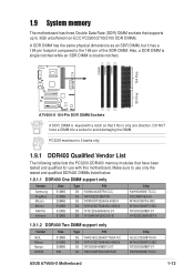
...the SDR DIMM. DO NOT force a DIMM into a socket to avoid damaging the DIMM. DIMM1 DIMM2 DIMM3 104 Pins 80 Pins A7V600-X ® A7V600-X 184-Pin DDR DIMM Sockets A DDR DIMM is double notched. PC3200 maximum to 2 banks only. 1.9.1 DDR400 Qualified Vendor List... DS SS SS P/N MAG16UL3264D1TG5A-KC MT16VDDT6464AG-40BC4 NT256D64S88B1G-5T MDOSS6F3G31JB1EAE Chip GL3LC32G88TG-5A MT46V32M8TG-5BC NT5DS32M8BT-5T K4H560838D-TCC4 ASUS A7V600-X Motherboard 1-13 1.9 System memory The motherboard has three Double Data Rate (DDR) DIMM sockets that supports up to 3GB unbuffered non-ECC PC3200/2700/2100 ...
...the SDR DIMM. DO NOT force a DIMM into a socket to avoid damaging the DIMM. DIMM1 DIMM2 DIMM3 104 Pins 80 Pins A7V600-X ® A7V600-X 184-Pin DDR DIMM Sockets A DDR DIMM is double notched. PC3200 maximum to 2 banks only. 1.9.1 DDR400 Qualified Vendor List... DS SS SS P/N MAG16UL3264D1TG5A-KC MT16VDDT6464AG-40BC4 NT256D64S88B1G-5T MDOSS6F3G31JB1EAE Chip GL3LC32G88TG-5A MT46V32M8TG-5BC NT5DS32M8BT-5T K4H560838D-TCC4 ASUS A7V600-X Motherboard 1-13 1.9 System memory The motherboard has three Double Data Rate (DDR) DIMM sockets that supports up to 3GB unbuffered non-ECC PC3200/2700/2100 ...
A7V600-X User's manual
Page 24
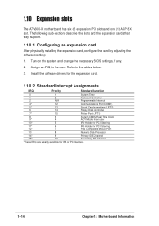
... ISA or PCI devices. 1-14 Chapter 1: Motherboard Information The following sub-sections describe the slots and the expansion cards that they support. 1.10.1 Configuring an expansion card After physically installing the expansion card, configure the card by adjusting the software settings. 1. 1.10 Expansion slots The A7V600-X motherboard has six (6) expansion PCI slots and...
... ISA or PCI devices. 1-14 Chapter 1: Motherboard Information The following sub-sections describe the slots and the expansion cards that they support. 1.10.1 Configuring an expansion card After physically installing the expansion card, configure the card by adjusting the software settings. 1. 1.10 Expansion slots The A7V600-X motherboard has six (6) expansion PCI slots and...
A7V600-X User's manual
Page 25
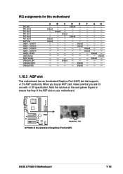
... 1 USB 1.1 UHCI 2 USB 1.1 UHCI 3 USB 1.1 UHCI 4 USB 2.0 EHCI USB Device AC97 Codec Onboard LAN Onboard SATA Onboard IDE A - shared - - - shared - IRQ assignments for 1.5v ® A7V600-X Accelerated Graphics Port (AGP) ASUS A7V600-X Motherboard 1-15 shared - - When you buy an AGP card, make sure that they fit the AGP slot on your...
... 1 USB 1.1 UHCI 2 USB 1.1 UHCI 3 USB 1.1 UHCI 4 USB 2.0 EHCI USB Device AC97 Codec Onboard LAN Onboard SATA Onboard IDE A - shared - - - shared - IRQ assignments for 1.5v ® A7V600-X Accelerated Graphics Port (AGP) ASUS A7V600-X Motherboard 1-15 shared - - When you buy an AGP card, make sure that they fit the AGP slot on your...
A7V600-X User's manual
Page 26
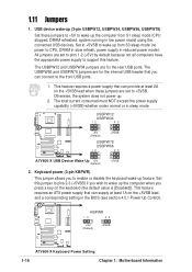
... supply that you can provide at least 1A on the +5VSB lead, and a corresponding setting in reduced power mode). A7V600-X KBPWR 12 23 +5V (Default) +5VSB ® A7V600-X Keyboard Power Setting 1-16 Chapter 1: Motherboard Information This feature requires an ATX power supply that can supply at least 2A on the keyboard (the default...
... supply that you can provide at least 1A on the +5VSB lead, and a corresponding setting in reduced power mode). A7V600-X KBPWR 12 23 +5V (Default) +5VSB ® A7V600-X Keyboard Power Setting 1-16 Chapter 1: Motherboard Information This feature requires an ATX power supply that can supply at least 2A on the keyboard (the default...
A7V600-X User's manual
Page 27
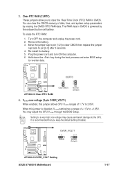
... RTC RAM: 1. Move the jumper cap to pin [1-2] to clear CMOS then replace the jumper cap back to re-enter data. A7V600-X OVER_VOLT1 12 23 Enable Disable (Default) ® A7V600-X OVER_VOLT Setting ASUS A7V600-X Motherboard 1-17 Turn OFF the computer and unplug the power cord. 2. Plug the power cord and turn ON the computer. 6. When... recommended that you to clear the Real Time Clock (RTC) RAM in CMOS is powered by erasing the CMOS RTC RAM data. Setting to 2.05V. A7V600-X ® A7V600-X Clear RTC RAM CLRTC 2 1 Clear CMOS 3 2 Normal (Default) 4.
... RTC RAM: 1. Move the jumper cap to pin [1-2] to clear CMOS then replace the jumper cap back to re-enter data. A7V600-X OVER_VOLT1 12 23 Enable Disable (Default) ® A7V600-X OVER_VOLT Setting ASUS A7V600-X Motherboard 1-17 Turn OFF the computer and unplug the power cord. 2. Plug the power cord and turn ON the computer. 6. When... recommended that you to clear the Real Time Clock (RTC) RAM in CMOS is powered by erasing the CMOS RTC RAM data. Setting to 2.05V. A7V600-X ® A7V600-X Clear RTC RAM CLRTC 2 1 Clear CMOS 3 2 Normal (Default) 4.
A7V600-X User's manual
Page 28
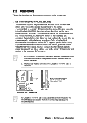
...connector. A7V600-X NOTE: Orient the red markings (usually zigzag) on the IDE ribbon cable to match the covered hole on each IDE connector is removed to PIN 1. Refer to the UltraDMA/133/100/66 master device. The hole near the blue connector on the motherboard. ...1. The UltraDMA/66 cable included in the motherboard package also supports UltraDMA/133/100. 1-18 Chapter 1: Motherboard Information Connect the cable's blue connector to the primary (recommended) or secondary IDE connector...
...connector. A7V600-X NOTE: Orient the red markings (usually zigzag) on the IDE ribbon cable to match the covered hole on each IDE connector is removed to PIN 1. Refer to the UltraDMA/133/100/66 master device. The hole near the blue connector on the motherboard. ...1. The UltraDMA/66 cable included in the motherboard package also supports UltraDMA/133/100. 1-18 Chapter 1: Motherboard Information Connect the cable's blue connector to the primary (recommended) or secondary IDE connector...

A7V600-X User's manual
Page 29
After connecting one end to the motherboard, connect the other end to the floppy drive. (Pin 5 is for a chassis designed with pin 5 plug). FLOPPY A7V600-X ® NOTE: Orient the red markings on ...When you wish to prevent incorrect insertion when using ribbon cables with intrusion detection feature. PIN 1 A7V600-X Floppy Disk Drive Connector 3. This requires an external detection mechanism such as a chassis intrusion sensor...with a jumper cap. 2. CHASSIS +5VSB_MB Chassis Signal GND A7V600-X ® A7V600-X Chassis Alarm Lead (Default) ASUS A7V600-X Motherboard 1-19
After connecting one end to the motherboard, connect the other end to the floppy drive. (Pin 5 is for a chassis designed with pin 5 plug). FLOPPY A7V600-X ® NOTE: Orient the red markings on ...When you wish to prevent incorrect insertion when using ribbon cables with intrusion detection feature. PIN 1 A7V600-X Floppy Disk Drive Connector 3. This requires an external detection mechanism such as a chassis intrusion sensor...with a jumper cap. 2. CHASSIS +5VSB_MB Chassis Signal GND A7V600-X ® A7V600-X Chassis Alarm Lead (Default) ASUS A7V600-X Motherboard 1-19
A7V600-X User's manual
Page 30
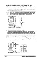
...1A on the +5-volt standby lead (+5VSB). The system may become unstable and may damage the motherboard components. ATXPWR1 A7V600-X ® +3.3VDC -12.0VDC GND PS_ON# GND GND GND -5.0VDC +5.0VDC +5.0VDC A7V600-X ATX Power Connector +3.3VDC +3.3VDC GND +5.0VDC GND +5.0VDC GND PWR_OK +5VSB +12....0VDC 1-20 Chapter 1: Motherboard Information Connect the fan cables to an ATX 12V power supply. ATX power connectors (20-...
...1A on the +5-volt standby lead (+5VSB). The system may become unstable and may damage the motherboard components. ATXPWR1 A7V600-X ® +3.3VDC -12.0VDC GND PS_ON# GND GND GND -5.0VDC +5.0VDC +5.0VDC A7V600-X ATX Power Connector +3.3VDC +3.3VDC GND +5.0VDC GND +5.0VDC GND PWR_OK +5VSB +12....0VDC 1-20 Chapter 1: Motherboard Information Connect the fan cables to an ATX 12V power supply. ATX power connectors (20-...


